1
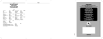
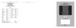
Version 3.0
TL21 PROGRAMMER
USER MANUAL
Version 3.0
Date: September 2004
English Edition
Azk
oyen Medios de P
ago, S
Azko
Pa
S.. A. hereby reserves the right to introduce, without prior notice, any
technical improvements derived from its constant research.
The names of the products and the companies included or represented herein are the registered trademarks of their respective owners.
Editado Noviembre 7, 2004
USER MANUAL
-3-
Contents
1. Introduction ------------------------------------------------------------------------ 5
2. The TL21 Programmer ---------------------------------------------------------- 6
2.1 Presentation of the Basic Kit --------------------------------------------- 6
2.2 General Description of the TL21 ---------------------------------------- 7
2.3 Functions of the TL21 Programmer ------------------------------------ 9
2.3.1 Description of the TL21 Programmer Functions --- 10
TURNING ON WITHOUT THE POWER ADAPTER ----------- 10
PROGRAMMING -------------------------------------------- 11
ADJUSTMENTS --------------------------------------------- 12
CONFIGURATION ------------------------------------------- 12
FIRMWARE ------------------------------------------------- 13
IDENTIFY MECHANISM ------------------------------------- 13
CONNECT TO PC ------------------------------------------ 15
EXACTOR PAYOUT UNIT INTERFACE ---------------------- 16
OPTIONS --------------------------------------------------- 17
TURNING ON WITH THE POWER ADAPTER -------------- 22
TURN OFF THE TL21 ------------------------------------- 23
2.4 Operating Mode ------------------------------------------------------------- 24
2.4.1 Obtaining Data -------------------------------------------------- 24
PRIOR REQUISITES --------------------------------------------------- 24
THE PROCESS OF OBTAINING DATA ---------------------------- 25
2.4.2 Coin Validator and Payout Unit Exactor Reprogramming
CONNECTION TO THE COIN VALIDATOR ---------------------- 25
CONNECTION TO THE EXACTOR PAYOUT UNIT ------------ 26
PROGRAMMING (REFERENCE NUMBER) ------------------ 27
ADJUSTMENTS --------------------------------------------- 28
CONFIGURATION ------------------------------------------- 29
DOWNLOAD FIRMWARE ----------------------------------- 30
REPROGRAMMING PROCESS ------------------------------------ 31
CONNECTION TO THE PAYOUT UNIT --------------------------- 34
2.4.3 Reprogramming AN-8000 Payout Units ---------------- 34
PROCESS OF REPROGRAMMING THE PAYOUT UNIT ----- 35
THE PROCESS OF REPROGRAMMING
THE ASSOCIATED COIN VALIDATOR ---------------------------- 37
2.4.4 Reading of Adjustments and Configurations -------- 39
2.5 Complements and Accessories ---------------------------------------- 41
2.6 List of Complements and Accessories ------------------------------ 45
3. Obtaining Files Via Internet (Web page & e-mail) -------------------- 47
3.1 User Validation -------------------------------------------------------------- 47
3.2 Request for Files ----------------------------------------------------------- 49
3.3 Other Operations ----------------------------------------------------------- 53
25
-4-
TL21 PROGRAMMER V3.0
ATTENTION!
THIS MANUAL IS ONLY FOR TL21’s THAT
INCORPORATE VERSION 2.0 OF THE OPERATING
SOFTWARE.
PREVIOUS MODELS MUST CONTINUE TO USE THE
MANUAL FOR VERSION 1.2 OR VERSION 2.0
Editado Noviembre 7, 2004
USER MANUAL
-5-
1. INTRODUCTION
The Portable Remote Programmer for Coin Validators and Payout Units (Hereafter the
TL21) is an autonomous, portable, and easily managed system conceived and designed to
facilitate reprogramming and communication with the Coin Validators and Payout units
manufactured by AZKOYEN, "at the machine".
For reprogramming with the TL21, it is not necessary to use any kind of coin or token, given
that its technology is based on the Coin Validator calibration.
What is the calibration?
During the manufacturing process, Coin Validators are checked one by one, and the data
obtained from this check are collected in a large database. These data will subsequently
serve to prepare new coin PROGRAMMING exactly according to each Coin Validator, without the need to use coins or tokens. All Coin Validators are each finally marked with a
different serial number, which is used to identify the Coin Validator.
Once a selector is programmed, a series of its parameters that take part in accepting or
rejecting a coin can be modified, for example in order to prevent frauds or in order to accept
new coin mintings. This process consists of downloading to the Selector a data file called
ADJUSTMENTS. There can be various adjustments to the same programming, and the
downloaded adjustments can be cancelled, thereby restoring the original programming.
When the device accepts a coin, its interaction with the “exterior” can be modified. This group of
adjustable parameters is called the CONFIGURATION, and it can be downloaded to the device.
The internal program executed on the device, and which makes it behave in a certain way,
is called the FIRMWARE, and the device can also be updated through this tool.
The TL21 included in the standard kit is configured for the L66S, LS6, MODULAR X, LV5,
ES525-UK, ES525-BDTA (selectors for vending machines and gaming machines) families
of selectors and for the AN-8000 and EXACTOR payout unit series. The TL21 included in
the Basic Kit is configured for the L66S, LS6, LV5 and X6 families of selectors. Through a
personalised card located on the battery housing (see figure 6) and the corresponding
connection cables, it can be configured to support other kinds of selectors. See section
«2.5. COMPLEMENTS AND ACCESSORIES», for more information.
The elements necessary for being able to correctly operate the TL21 are structured as
shown in the following schematic:
Coin Validator
Internet
www
@
SmartMedia
PC
File
Payout Unit AN 8000
Payout Unit
EXACTOR
TL21 PROGRAMMER V3.0
-6-
2. THE TL21 PROGRAMMER
2.1 PRESENTATION OF THE BASIC KIT
The basic kit being presented here, which is necessary for updating Coin Validators, is
equipped with the following components.
1
2
4
3
10
9
8
Figure 1. Basic Kit. Ref. 41105971-0
7
6
1 Carrying bag.
2 Adapter card.
3 TL21 Programmer.
4 RS232 cable.
5 16-way parallel cable.
6 Adapter for SmartMedia Memory and software.
7 8-Mb SmartMedia Memory Card.
8 Package of 4, LR6 batteries.
9 CD with applications for PC and Manuals.
10 5V power supply adapter.
5
Editado Noviembre 7, 2004
-7-
USER MANUAL
2.2 GENERAL DESCRIPTION
OF THE
TL21
The TL21 Programmer is a hand-held terminal that consists of the following:
1 LCD screen and a 45-key alphanumeric keyboard.
The LCD display format is 4 x 16 characters, grey-coloured.
The keyboard includes all of the keys that allow navigating among the various options that are offered by
the TL21 menu.
Pg Up
Home
F1
A
7
8
9
4
5
6
END
Pg Dn
1
2
\
,
INS
ESC
DEL
0
3
F5
E
LCD Screen
START
45-key alphanumeric
keyboard
ENTER
Figure 2. Navigation keys
Figure 3. Programmer
2 Connection ports for Coin
Validators and for PC’s (At the
top).
RS232 serial connection
16-way parallel connection
3 Slot for the SmartMedia card
(On the right-hand side).
Eject button
Figure 5. Input for SmartMedia
Figure 4. Programmer (top part).
-8-
TL21 PROGRAMMER V3.0
4 Housing for power cells or rechargeable batteries, LR6 type
(At the back).
Personalised Card
5 Personalised card. This card is
necessary in order to adapt the
TL21 to the various kinds of
Coin Validators and Payout
UnitsIt is snapped on next to the
battery compartment.(At the
back).
Figure 6. Housing for power cells or rechargeable batters, LR6 type, and
cover.
ATTENTION !! ONLY THE POWER
SUPPY ADAPTER PROVIDED BY
AZKOYEN SHOULD BE CONNECTED
Cover fastening screw.
6 5 V DC / 1.2 A power supply
input (On the right-hand side).
Figure 7. Power supply input for external
adapter.
ATTENTION !!
ONLY THE POWER SUPPY ADAPTER PROVIDED
BY AZKOYEN SHOULD BE CONNECTED.
THE USE OF ANY OTHER POWER SUPPLY
ADAPTER MAY CAUSE SERIOUS DAMAGE TO THE
PROGRAMMER.
Editado Noviembre 7, 2004
-9-
USER MANUAL
2.3 FUNCTIONS
OF THE
TL21 PROGRAMMER
The TL21 Programmer offers various possibilities and menus for working with
its multiple options. The general schematic of the functions that the Programmer includes are presented below.
Version 3.0
PROGRAMMING
ADJUSTMENTS
CONFIGURATION
DUMP TO
READ FROM
ERASE READING
BACK
TYPE OF CONNECTOR:
16 PIN PARALLEL
SUB D9 RS232 SERIAL
BACK
FIRMWARE
IDENTIFY
PAYOUTUNIT I/F
COIN VALIDATOR TYPE(1):
TELEPHONY +5V
TELEPHONY + 9V
S81
L86SDUAL
S81PS
L86SPS
S82
LS8
S82NS
SA56S
S86PS
LS8PS
MODULAR 5V
L86S
ATRÁS
SA54N
N2G
MODULAR 9V
OPERATOR CODE
ATRÁS
POWER SUPPLY: PW CELLS
STANDARD
L66S
LS6
ES525BDTA
ES525UK
LV5
MODULAR
ATRÁS
CONNECT TO PC
BATTERIES
BACK
OPTIONS
SWITCH OFF
LANGUAGE: SPANISH
ENGLISH
GERMAN
ITALIAN
FRENCH
PORTUGUESE
BACK
BATTERY STATUS
PREPARE BATTERY
PROGRAM CLOCK
CHANGE DATE
BACK
DESACTIVATE
ACTIVATE
BACK
(1)The type and quantity of Coin Validators that appear in this menu depend on
the adapter card (see figure 6) that is installed at the back of the TL21.
TL21 PROGRAMMER V3.0
- 10 -
2.3.1 DESCRIPTION OF THE TL21 PROGRAMMER FUNCTIONS
The options of the TL21 Programmer that allow the Coin Validators and Payout Units to be
clearly and simply updated, thereby providing all of the information for the process, are
displayed and activated by using the navigation keys.
PRINCIPAL KEYS
ENTER
8
Validates the option selected.
2
Home
7
They select the various menu options.
4
Returns to the previous screen
(like the "Back" option).
Display message
with more than 16
characters.
6
END
Select the first menu option.
1
Select the last menu option.
Pg Dn
Pg Up
Back to the previous screen.
9
\
ESC
F1
F5
A
E
Forward to the next screen.
3
The screen intensity can be adjusted at any time by using these
two keys.
+ TURNING ON WITHOUT THE POWER ADAPTER
It is turned on by keeping the START button
pressed until the initial screen appears.
Press
START
->
->
->
->
CASTELLANO
ENGLISH
DEUTSCH
ITALIANO
->
->
->
->
DEUTSCH
ITALIANO
FRANCAISE
PORTUGUES
The first time that the TL21 is started, a menu
appears in which the desired language must
be selected from among those available:
Home
7
Pg Up
8
Pg Dn
END
1
9
2
3
Editado Noviembre 7, 2004
- 11 -
USER MANUAL
Press
ENTER
TL 21
v3.0
(c) AZKOYEN 2004
MEDIOSdePAGO SA
Press Key
Press Key
TL21v3.0
1/3
-> Programming
-> Adjustments
-> Configuration
TL21v3.0
2/3
-> Firmware
-> Identify
-> Connect to PC
This screen blinks when displayed, and the main
menu is accessed by pressing any key.
Those keys can be fit the intensity of the display:
-
F1
F5
A
E
+
The various possibilities are activated by using
the navigation keys. The option that is blinking
is chosen by pressing ENTER.
Home
7
Pg Up
8
Pg Dn
END
1
9
2
3
ENTER
TL21v3.0
3/3
-> PayoutUnit I/F
-> Options
<- Switch Off
+ PROGRAMMING
TL21v3.0
1/3
-> Programming
-> Adjustments
-> Configuration
This option allows programming the device using
the desired Programming reference.
In order to perform the programming process of
any device, see the «2.4 OPERATING MODE»
section.
TL21 PROGRAMMER V3.0
- 12 -
+ ADJUSTMENTS
TL21v3.0
1/3
-> Programming
-> Adjustments
-> Configuration
Press
ENTER
> Adjustments1/2
-> Dump to
-> Read from
-> Erase Reading
This option allows performing the following functions related to adjustments of the device:
9 Downloading adjustment profiles
to the devices. In order to download
adjustments to any device, see the
«2.4 OPERATING MODE» section.
9 Reading the adjustment data of the
device and storing the data in
SmartMedia as a file.
9 Deleting any of the files that have
been created when reading the adjustments of a device.
order to go through the process of storing the
adjustments of the device that have been read
or to erase these readings from the SmartMedia
memory, see the «READING ADJUSTMENTS AND
CONFIGURATIONS» section.
+ CONFIGURATION
TL21v3.0
1/3
-> Programming
-> Adjustments
-> Configuration
Press
ENTER
> Adjustments1/2
-> Dump to
-> Read from
-> Erase Reading
This option allows performing the following functions related to the configuration of the device.
9 Downloading configuration files to
the devices. In order to download
configurations to any device, see the
«2.4 OPERATING MODE» section.
9 Reading the configuration data of
the device and storing the data in
SmartMedia as a file.
9 Deleting any of the files that have
been created when reading the
configuration of a device.
In order to go through the process of storing the
configurations of the device that have been
read or to delete these readings from the
SmartMedia memory, see the «READING ADJUSTMENTS AND CONFIGURATIONS» section.
Editado Noviembre 7, 2004
- 13 -
USER MANUAL
+ FIRMWARE
TL21v3.0
2/3
-> Firmware
-> Identify
-> Connect to PC
This option allows updating the Firmware of a
Selector or Payout unit.
In order to update the Firmware of any Selector
or Payout unit, see the «2.4 OPERATING MODE»
section.
+ IDENTIFY MECHANISM
TL21v3.0
2/3
-> Firmware
-> Identify
-> Connect to PC
A screen is displayed, which shows the options
that allow making the connection. The option
that is blinking is the one that is activated.
Press
ENTER
> CONNECTOR TYPE
-> 16pin parallel
-> Sub D9 Serial
<- Back
Home
7
Pg Up
8
1
9
Pg Dn
END
2
ENTER
3
9 16-pin parallel: This connector allows completely autonomous reprogramming of the
Coin Validators, whereby the TL21 supplies
the power necessary to the Coin Validator
through its internal power cells or batteries.
9 SUB-D9 serial: This connector allows
configuring the AN 8000 and EXACTOR series Payout units. In this case, the power
for the Coin Validator and the Payout unit
must be supplied by the machine to which
they are connected.
9 Back: It returns to the previous menu.
>>
->
->
->
VALIDATOR 1/3
L66S
L66S CCTALK
LS6
>>
->
->
->
VALIDATOR 2/3
ES525 BDTA
ES525 UK
LV5
>> VALIDATOR
-> MODULAR
<- Back
This option allows identifying the Coin Validator connected to the TL21 without having to perform any
kind of programming. The information remains
stored in the programmer, and it can be extracted
later using the HeUs Software.
3/3
By pressing ENTER while holding down the Back
option, or ESC, it returns to the main menu.
After having selected the kind of connector, select the kind of device to be identified.
Activate the various possibilities by using the navigation keys. Press ENTER to select the flashing option.
Home
7
Pg Up
8
Pg Dn
END
1
9
2
3
TL21 PROGRAMMER V3.0
- 14 Press
ENTER
Num:
xxx(1)
(2)
xxxxxxxx ,vx(3)
Identifying
Press Key
xx-xxx(1)
xM(2)
P:
C:
xxx(3)
xxx(4)
xxx(5)
Home
7
Pg Up
8
Pg Dn
END
1
9
2
3
Once the kind of device has been selected, its
identifying data are displayed.
For non-modular devices, the following is displayed:
1
2
3
For modular devices, the following is displayed:
1
2
3
4
5
6
7
ENTER
M1:[
(7)
PG AJ CF
M2:[
(7)
PG AJ CF
xxx(6)]
FWv2(9)
xxx(8)]
FWv2(9)
Serial number.
Reference.
Reference version.
8
9
Type of Selector.
Number of modules that comprise
the device.
Serial number.
Reference – version of the device.
Configuration of the device.
Name of module 1.
Functions supported by the module:
PG: Program.
AJ: Adjust.
CF: Configure. FW: Install Firmware.
Name of module 2.
Firmware version of the module.
Editado Noviembre 7, 2004
USER MANUAL
- 15 -
+ CONNECT TO PC
TL21v3.0
2/3
-> Firmware
-> Identify
-> Connect to PC
Press
This option allows connecting the TL21 to a PC
using an RS232 serial cable supplied for such
purpose.
The TL21 records all of the programming and
identification operations that it performs. In order to access these data, it is necessary to use
the HeUs Software.
ENTER
By pressing ENTER, the TL21 goes idle and
shows the informational message.
Connecting ...
Press
Return to the main menu by pressing any key.
\
ESC
LOG almost full
Download to PC
LOG full,
Serial number not
recorded
Download to PC
The TL21 memorises up to 2000 operations.
When there are 50 operations left until the
memory is full, a message is displayed.
If the memory is full, a warning message is displayed, and it does not store any more operations until the data are downloaded to a PC
and the memory is erased. See HeUs Software
manual.
TL21 PROGRAMMER V3.0
- 16 -
+ EXACTOR PAYOUT UNIT INTERFACE
TL21v3.0
3/3
-> PayoutUnit I/F
-> Options
<- Switch Off
Press
ENTER
Connecting ...
This option allows operating the TL21 as the
keypad and screen of an EXACTOR Payout
unit. See the «CONNECTION TO EXACTOR PAYOUT UNIT» section.
By pressing ENTER, the TL21 will establish communications with the connected device. During the connection process, it will show a message informing of the operation.
When the connection is successfully made, the
TL21 will show the kind of device connected. If
it is a payout unit, it will show the data on screen
and will accept orders on its keypad for the payout unit.
The key correspondence with the payout unit is
the following:
F1
Press
\
ESC
A
8
A
2
B
4
D
F2
B
F4
D
F3
C
P
ENTER
C
EXE
P
For more information, consult the EXACTOR Payout Unit manual.
In order to exit the Payout Unit interface function,
press ESC.
Editado Noviembre 7, 2004
USER MANUAL
- 17 -
+ OPTIONS
TL21v3.0
3/3
-> PayoutUnit I/F
-> Options
<- Switch Off
Press
ENTER
>
->
->
->
OPTIONS
1/3
Operator Code
Power supply
Language
>
->
->
->
OPTIONS
2/3
Battery Status
Battery Condi.
Program Clock
This function allows accessing the various configuration options of the TL21.
It shows the next menu:
9 Operator code: It confirms or
changes the Operator Code in order to operate with AN 8000 Payout
units.
9 Power supply: It selects the kind of
power supply.
9 Language: It selects the language
of the TL21 menus.
9 Battery status: It shows the available battery charge.
9 Prep. Batteries: It prepares batteries in order to recharge them.
9 Program Clock:Programs the
date/time.
9Change Date:Allows the date/time
to be changed.
9 Back: It returns to the main menu.
> OPTIONS
3/3
-> Change Date
<- Back
By pressing ENTER while holding down the Back
option, or ESC, it returns to the main menu.
TL21 PROGRAMMER V3.0
- 18 OPERATOR CODE
>
->
->
->
OPTIONS 1/3
Operator Code
Power supply
Language
Press
ENTER
Introduce Code
Current:
New:
0000
----
Introduce code
and press
ENTER
POWER
>
->
->
->
This option allows programming an Operator
Code in the TL21 that will subsequently serve
as an identifier for communications with the AN
8000 Payout Unit. This code must coincide with
the one entered into the AN 8000 using function F475 in the programming menu of the
same.
In order to program the code in the TL21, just
enter 4 digits and press ENTER. If a wrong
number is entered, press DEL to erase what
was entered, and then start again.
If the TL21 is being used to reprogram an AN
8000, and the code does not coincide, a failed
communication message automatically appears
and it returns to the start menu.
SUPPLY
OPTIONS 1/3
Operator Code
Power supply
Language
Press
This option allows selecting the kind of power
supply for the TL21.
The following menu is displayed:
9 Power cells: This option is selected
when the TL21 is powered by
STANDARD LR6 power cells.
ENTER
>> Power supply
-> Cells
-> Batteries
9 Batteries: This option is selected
when LR6 RECHARGABLE batteries are used.
It thus allows the 5V power supply
adapter to recharge the batteries
when necessary.
ATTENTION!
DO NOT CONFIGURE THE EQUIPMENT IN THE
"BATTERIES" MODE IF POWER CELLS ARE
INSTALLED, SINCE THE TL21 COULD ENTER THE
RECHARGE MODE, THEREBY CAUSING THE POWER
CELLS TO HEAT UP AND EXPLODE.
Editado Noviembre 7, 2004
- 19 -
USER MANUAL
LANGUAGE
>
->
->
->
OPTIONS
1/3
Operator Code
Power supply
Language
Press
This option allows selecting the language that is
used to display the TL21 menus.
ENTER
>>
->
->
->
Language
Spanish
English
German
1/3
>>
->
->
->
Language 2/3
Italian
French
Portuguese
The various possibilities are activated using the
navigation keys. By pressing ENTER, the language of the TL21 menu is selected.
Home
>> Language
<- Back
7
Pg Up
8
Pg Dn
END
1
9
2
3
3/3
ENTER
Press ESC to return to the main menu.
BATTERY
>
->
->
->
STATUS
OPTIONS
2/3
Power supply
Language
BatteryStatus
Press
This function is only operational if the «Power
supply – Batteries» option has been previously
selected.
ENTER
Battery Status
-[
This option shows the power level of the rechargeable TL21 batteries.
]+
By pressing ENTER, it displays the battery status.
”
TL21 PROGRAMMER V3.0
- 20 PREPARE BATTERY
>
->
->
->
OPTIONS 2/3
Language
Battery Status
Battery Condi.
Press
ENTER
BATTERY CHARGER
Discharging
This option allows preparing the rechargeable
batteries for a full charge. When this option is
selected, the batteries are discharged completely, and they are then recharged.
After the battery is conditioned (discharged and
recharged), the power adapter must be disconnected for half an hour, and then it can be subsequently connected again.
It is only operational if the «Power supply – Batteries» option has been previously selected and
the 5V power supply adapter is connected to
the TL21.
It is recommendable to perform this operation
once a month in order to extend the life of the
rechargeable batteries.
By pressing ENTER, it proceeds to prepare the
batteries.
Press START to cancel the process and turn off
the TL21.
9 The TL21’s with the «-0» and «-1» references
are turned off by disconnecting them from the
power adapter.
See the section, «ERRORS WHEN CHARGING AND DISCHARGING THE BATTERIES.»
PROGRAM CLOCK
>
->
->
->
OPTIONS 2/3
Battery Status
Battery Condi.
Program Clock
Press
This option allows the time and date to programmed on the TL21.
For the TL21’s with the «-0» and «-1» reference,
these values are permanently set, given that
they do not have a clock.
ENTER
Press any key to modify the date and time.
hh:mm:ss
dd/mm/yy
Editado Noviembre 7, 2004
- 21 -
USER MANUAL
Use the right and left arrow keys to select the fields
to be modified.
Press any key
Use the up and down arrow keys to increase or
decrease the value.
Change Date
dd/mm/yy hh:mm
ESC
9Press ENTER to save the changes.
9 Press ESC to leave the menu without saving
the changes
ENTER
\
ESC
ENTER
8
2
4
6
CHANGE DATE
>
->
->
->
OPTIONS 2/3
Battery Condi.
Program Clock
Change Date
Press
>>
->
->
->
This function is only operational in the TL21’s with
the «-0» and «-1» references.
It allows the date and time change to be enabled
in the first Identify or Program option after being turned on.
ENTER
Change Date
Desactivate
Activate
Back
The desired option is selected by using the navigation keys and pressing ENTER.
TL21 PROGRAMMER V3.0
- 22 -
+ TURNING ON WITH THE POWER ADAPTER
BATTERY CHARGER
Charging
ERRORS
WHEN
CHARGING
AND
In order to charge the batteries, connect the external power adapter while the TL21 is turned
off. The TL21 must be configured as follows:
Options ÎPower supply Î Batteries.
DISCHARGING BATTERIES
Errors may occur when the batteries are charged or discharged, which errors are shown
below.
Power
not connected
Verify
Batteries
High Batteries
temp.
High Batteries
volt.
When the option to condition the batteries is entered, the power adapter is not connected to
the TL21.
This message advises that one of the two batteries is not installed or that the batteries are reversed.
Check batteries.
The temperature of the batteries is too high for
charging and discharging.
Disconnect the TL21 for 30 minutes.
The voltage of the batteries is too high for charging and discharging.
Disconnect the TL21 for 30 minutes.
Editado Noviembre 7, 2004
USER MANUAL
- 23 -
+ TURN OFF THE TL21
TL21v3.0
3/3
-> Connect to PC
-> Options
-> Switch Off
This operation turns off the TL21. In any event,
the programmer disconnects itself after 3 minutes if no operation has been performed and it
is being powered by power cells or batteries.
The TL21 Programmer is turned off by pressing
ENTER.
The TL21 can also be turned off by pressing the
START key.
9The TL21’s with the «-0» and «-1» references
are turned off by disconnecting them from the
power adapter.
- 24 -
TL21 PROGRAMMER V3.0
2.4 OPERATING MODE
2.4.1 OBTAINING DATA
Before being able to operate with the TL21 Programmer, all of the elements must be
configured with the software necessary so that they all work together correctly and in
order to obtain the data for the update.
PRIOR REQUISITES
○ ○ ○ ○ ○ ○ ○ ○ ○ ○ ○ ○ ○ ○ ○
1 The SmartMedia memory module must be formatted. This operation is performed once the SmartMedia controllers have been installed in the equipment. For this simple process, just choose the appropriate controller for your
operating system (W95, W98, WM, NT4, W2000) from the CD-ROM or the
floppy disk supplied with the adapter.
In order to copy files from a PC to the SmartMedia card, insert the card
adapter into the 3-1/2" floppy disk drive of the computer.
2 Have an internet connection available with authorised access to the
SmartMedia Card
Adapter
Figure 8. Adapter with the
SmartMedia Card.
AZKOYEN Medios de Pago S. A. web page and have an e-mail account in
order to receive the programming. See point "3. OBTAINING FILES VIA INTERNET."
3 Have the HeUs Software installed in your PC or computer equipment. See
the instructions on HeUs Software manual.
Editado Noviembre 7, 2004
- 25 -
USER MANUAL
THE PROCESS OF OBTAINING DATA
○ ○ ○ ○ ○ ○ ○ ○ ○ ○ ○ ○ ○ ○ ○ ○ ○ ○ ○ ○ ○ ○ ○ ○ ○ ○
After having completed the requisites in the preceding point, the basic process for obtaining data is the following:
1 The desired programs are obtained by using the Azkoyen Medios de Pago S. A. web
page and an e-mail address. To do so, it is necessary to be authorised as a user.
2 The HeUs Software is then used to copy the new programs to
the SmartMedia memory card while
its corresponding adapter is connected to the PC.
3 The SmartMedia card is then
inserted into the TL21.
In order to obtain a complete description
of this process, follow the instructions
in point "3. OBTAINING FILES VIA INTERNET"
and HeUs Software manual.
Figure 9. SmartMedia
card in the TL21.
2.4.2 COIN VALIDATOR AND PAYOUT UNIT EXACTOR
REPROGRAMMING
REPROGRAMMING THE COIN VALIDATOR DOES NOT
ALWAYS MEAN COMPLETE ADAPTATION OF THE MACHINE.
IT IS POSSIBLE THAT IF THE TYPE OF MONETARY CHANGE
OR ACCEPTED COINS HAVE BEEN CHANGED, THEN
OTHER COMPONENTS SUCH AS THE RETURNER TUBES,
HOPPERS, ETC., MAY ALSO NEED TO BE CHANGED.
CONNECTION TO THE COIN VALIDATOR
○ ○ ○ ○ ○ ○ ○ ○ ○ ○ ○ ○ ○ ○ ○ ○ ○ ○ ○ ○ ○ ○ ○ ○ ○ ○ ○ ○ ○ ○
The TL21 communicates directly with
the Coin Validator by using the 16way parallel cable, thereby supplying the Coin Validator with power
and identifying the data of the same.
While using a connector similar to the
one in the diagram, the connection
must be made with the «feet» down
for the L66S, LS6, LS8, LV5, S81,
L86S and ES525BDTA Coin
Validators, and with the «feet» up of
for the ES525 UK Coin Validators.
For all other kinds of Coin Validators,
ensure that the connector tabs are
aligned.
Figure 10. Programmer connected
to the Coin Validator.
- 26 -
TL21 PROGRAMMER V3.0
CONNECTION TO THE EXACTOR PAYOUT UNIT
○ ○ ○ ○ ○ ○ ○ ○ ○ ○ ○ ○ ○ ○ ○ ○ ○ ○ ○ ○ ○ ○ ○ ○ ○ ○ ○ ○ ○ ○ ○ ○ ○ ○ ○
The TL21 is connected to the EXACTOR Payout Unit
as shown in figure 10b using the EXACTOR Data
Transmission Cable (Sub D9 Serial, not supplied).
This cable is only for establishing communications with
the Payout Unit and the associated Selector. The
power supply of them both must be provided through
the machine to which they are connected.
Figure 10b. Programmer connected to the
EXACTOR Payout Unit.
Editado Noviembre 7, 2004
USER MANUAL
- 27 -
+ PROGRAMMING (REFERENCE NUMBER)
TL21v3.0
1/3
-> Programming
-> Adjustments
-> Configuration
Press
ENTER
This option allows selecting the programming to
be introduced into the Coin Validator or Payout Unit, thus giving them a new reference
number.
A screen is displayed, which gives information on
the content of the SmartMedia card, thereby
indicating the following:
9 The reference numbers that the
SmartMedia card contains.
1/5
41083562-3,vxx
[L66S
]
9 The reference number of the new
programming.
9 The kind of Coin Validator.
9 Informational comment.
Press
ENTER
By pressing ENTER, it selects the reference
shown on screen and continues. See «REPROGRAMMING PROCESS».
By pressing ESC, it returns to the main menu.
IT SUPPORTS THE FOLLOWING
SMARTMEDIA FORMATS:
9 V1. WITHOUTH THE REFERENCE VERSION.
9 V2. WITH THE REFERENCE VERSION.
(SEE THE HEUS SOFTWARE MANUAL).
THE CAPACITY OF SMARTMEDIA IS LIMITED TO
32 REFERENCES AND 254 FILES.
TL21 PROGRAMMER V3.0
- 28 -
+ ADJUSTMENTS
TL21v3.0
1/3
-> Programming
-> Adjustments
-> Configuration
Press
A screen is displayed, which provides information on the content of the SmartMedia memory,
thereby indicating the following:
9 Number of adjustments that the
SmartMedia memory contains.
ENTER
9 Date when the adjustment file was
created.
> Adjustments1/2
-> Dump to
-> Read from
-> Erase Reading
Press
This option allows selecting the adjustments to
be downloaded to the Selector or Payout Unit.
9 The kind of Selector.
9 Name that identifies the adjustments.
ENTER
1/4
03/08/2004 14:23
[X6-M6S
]
Adjustments name
By pressing ENTER, it selects the file that is
shown on screen and continues. See «REPROGRAMMING PROCESS».
Press ESC to return to the main menu.
ADJUSTMENT DOWNLOADING CAN ONLY BE
PERFORMED ON MODULAR DEVICES.
THE CAPACITY OF SMARTMEDIA IS LIMITED TO 32
ADJUSTMENTS (254 FILES).
(SEE THE HeUs SOFTWARE MANUAL).
Editado Noviembre 7, 2004
USER MANUAL
- 29 -
+ CONFIGURATION
TL21v3.0
2/3
-> Firmware
-> Identify
-> Connect to PC
Press
ENTER
> Firmware
-> Dump to
-> Read from
-> Erase Reading
Press
This option allows selecting the configuration to
be downloaded to the Selector or Payout unit.
A screen is displayed, which provides information on the content of the SmartMedia memory,
thereby indicating the following:
9 Number of configurations that the
Smart Media memory contains.
9 Date when the configuration file was
created.
9 The kind of Selector.
9 Name that identifies the configuration.
ENTER
1/4
03/08/2004 14:23
[X6-M6S
]
Config. Name
By pressing ENTER, it selects the file that is
shown on screen and continues. See «REPROGRAMMING PROCESS».
Press ESC to return to the main menu.
CONFIGURATION DOWNLOADING CAN ONLY BE
PERFORMED ON MODULAR DEVICES.
THE CAPACITY OF SMARTMEDIA IS LIMITED TO 32
CONFIGURATIONS (254 FILES).
(SEE THE HeUs SOFTWARE MANUAL).
TL21 PROGRAMMER V3.0
- 30 -
+ DOWNLOAD FIRMWARE
TL21v3.0
2/3
-> Firmware
-> Identify
-> Connect to PC
Press
This option allows selecting the Firmware to be
downloaded to the Selector or Payout unit.
A screen is displayed, which provides information on the content of the SmartMedia memory,
thereby indicating the following:
9 Number of Firmwares that the
SmartMedia memory contains.
ENTER
9 Date when the Firmware was created.
1/4
03/08/2004 14:23
[X6-M6S
]
Firmware Name
9 The kind of Selector.
9 Name that identifies the Firmware.
By pressing ENTER, it selects the file that is
shown on screen and continues. See «REPROGRAMMING PROCESS».
Press ESC to return to the main menu.
FIRMWARE DOWNLOADING CAN ONLY BE
PERFORMED ON MODULAR DEVICES.
THE CAPACITY OF SMARTMEDIA IS LIMITED TO 32
FIRMWARES (254 FILES).
(SEE THE HeUs SOFTWARE MANUAL).
Editado Noviembre 7, 2004
USER MANUAL
- 31 -
REPROGRAMMING PROCESS
○ ○ ○ ○ ○ ○ ○ ○ ○ ○ ○ ○ ○ ○ ○ ○ ○ ○ ○ ○ ○ ○
Press
1 We have previously selected the task to perform:
ENTER
9 PROGRAM.
9 ADJUST.
>
->
->
<-
Connector type
16pin parallel
Sub D9 Serial
Back
Press
ENTER
PROGRAMMING
9 CONFIGURE.
9 FIRMWARE.
and the data to download to the device.
2 Choose the «16PIN PARALLEL» connector whereby
communications is established with the Selector, or the «SUB D9 SERIAL» connector whereby
communications is established with modules that
comprise the EXACTOR Payout Unit.
3 When ENTER is pressed, the TL21 proceeds
to program the Coin Validator.
During this process, it is possible to use more than
one SmartMedia module.
TASK OK
-> Dump to
-> Back
TASK ERROR
-> Dump to
-> Back
Coin Validator
not connect
When the reprogramming is complete, the display shows a message that indicates the result
of the process.
9 Another Coin Validator can subsequently be
programmed by pressing ENTER.
9 By pressing ESC, it returns to the main menu.
If the TL21 is not able to establish communications with the Coin Validator, the following
screen is displayed:
9 Check the Coin Validator connections and the
battery level.
TL21 PROGRAMMER V3.0
- 32 -
Coin Validator
serial number
not found
In the event that the serial number of the Coin
Validator does not exist for the selected reference, the attached message is displayed.
9 Various SmartMedias can be entered until the programming of the selected reference with the serial
number of the connected Coin Validator is found.
If communication is interrupted during the process, the attached message appears.
9 Check the Coin Validator connections and the
battery level.
Adapter Board Not
Connected
Check the connection to the TL21 from the
Personaliser Card. See figure 6.
The selected Coin Validator cannot be programmed using the Personaliser Card that is
connected.
Task
NOT permitted
Communications
Error
Incorrect
Adapter Board
The data selected for downloading to the device
are not compatible with the same.
9 Check the specifications of the device and rerequest the corresponding programming.
NON-compatible
Programming
The device is not operational.
9 Download the Firmware that is appropriate for
this tool and or that is appropriate for the tools
indicated for such purpose.
Wrong
Firmware
The device is deprogrammed.
Wrong
Programming
9 Program the device using the desired reference.
Editado Noviembre 7, 2004
USER MANUAL
- 33 -
An error occurred when saving the data read in
the SmartMedia memory.
Error while
saving Data
9 Try to read again.
The available space for storing readings in the
SmartMedia memory is full.
NO Space
Unload to PC
9 Download the stored readings to a PC and free
up space in the memory.
- 34 -
TL21 PROGRAMMER V3.0
2.4.3 REPROGRAMMING AN-8000 PAYOUT UNITS
REPROGRAMMING THE PAYOUT UNIT DOES
NOT ALWAYS MEAN THE COMPLETE
ADAPATION OF THE MACHINE.
IT IS POSSIBLE THAT IF THE TYPE OF MONETARY
CHANGE OR ACCEPTED COINS HAVE BEEN
CHANGED, THEN THE RETURNER TUBE SYSTEM
MAY ALSO NEED TO BE ADAPTED.
The TL21 Programmer allows performing two completely different operations when it operates with the AN 8000 Payout Units:
1 Reprogram the payout unit. By selecting the appropriate reference, the following aspects can be reprogrammed: type of classification, accepted coins,
etc.
2 Reprogramming the associated Coin Validator without having to remove
it from the Payout Unit.
CONNECTION TO THE PAYOUT UNIT
○ ○ ○ ○ ○ ○ ○ ○ ○ ○ ○ ○ ○ ○ ○ ○ ○ ○ ○ ○ ○ ○ ○ ○ ○ ○ ○
The TL21 is connected to the AN 8000 Payout Unit by
using the AN 8000 connection cable bundle (Sub D9
Serial connector not supplied) as shown in figure 12.
This cable is only used for establishing communications with the Payout Unit and its associated Coin
Validator. The power supply of both must be provided
by the machine in which they are installed.
Figure 12. Programmer connected
to the Payout Unit.
Editado Noviembre 7, 2004
- 35 -
USER MANUAL
PROCESS OF REPROGRAMMING THE PAYOUT UNIT
○ ○ ○ ○ ○ ○ ○ ○ ○ ○ ○ ○ ○ ○ ○ ○ ○ ○ ○ ○ ○ ○ ○ ○ ○ ○ ○ ○ ○ ○ ○ ○ ○ ○ ○ ○ ○
1 The function F018 of the Payout Unit must be
activated in order to be able to establish communications with the TL21.
READY
CREDIT 0 PTS
Press
red key
Press
B
A
F018 CONFIGURE
PAYOUT UNIT
Press
C
EXE
F018 CONFIGURE
0- PARAMETERS
TL21v3.0
1/3
-> Programming
-> Adjustments
-> Configuration
Press
In order to do so, access the programming
menu of the Payout Unit by pressing the "red
key" and use the keys "A" or "B" in order to
search for the function F018. Be pressing "C/
EXE", a new menu is accessed, which displays
three options:
0. Used to configure the Parameters.
1. Used to configure Flash.
2. Used to configure the Coin Validator.
Keys A and B are used to change the kind of
configuring to be performed between "0. Parameters," "1. Flash," and "2. Coin Validator." In
this case, it is not necessary to change it, and
C/EXE should be pressed in order to select programming the parameters of the AN-8000
In order to carry out communications, it is necessary that the Operator Code entered into the
TL21 also be the same as the one programmed in the Payout Unit.
2 Once the Payout Unit has been prepared,
choose the "Select Programming" option from
the start screen of the TL21 and press ENTER.
ENTER
Ref 1 of 1
41089971-1,vx
[AN 8000
EXECUTIVE
]
3 Select the file that contains the data to be programmed. To do so, find the desired reference
by using keys «7» «8» and «9» or «1» «2» and
«3» and then press ENTER.
Home
Press
7
Pg Up
8
9
ENTER
Pg Dn
END
PROGRAMMING
1
2
3
- 36 -
Task OK
-> Dump to
-> Back
Task Error
-> Dump to
-> Back
TL21 PROGRAMMER V3.0
When the reprogramming finalises, the display
shows a message thereby indicating that the
process was completed successfully.
9 By pressing ENTER, another Payout Unit can
be programmed.
9 By pressing ESC, it returns to the main screen.
If the TL21 cannot establish communications with
the Payout Unit, the following screen is displayed:
Communications
Error
If the operator code configured in the TL21 does not coincide with the one in the AN 8000,
then the AN 8000 rejects the connection and communication is aborted. In this case, the
AN 8000 programming is not changed.
If the operator code does not coincide, the following message will appear.
Incorrect
Operator Code
Editado Noviembre 7, 2004
- 37 -
USER MANUAL
THE PROCESS OF REPROGRAMMING THE ASSOCIATED COIN VALIDATOR
○ ○ ○ ○ ○ ○ ○ ○ ○ ○ ○ ○ ○ ○ ○ ○ ○ ○ ○ ○ ○ ○ ○ ○ ○ ○ ○ ○ ○ ○ ○ ○ ○ ○ ○ ○ ○ ○ ○ ○ ○ ○ ○ ○ ○
1 The function F018 of the Payout Unit must be
activated in order to be able to establish communications with the TL21.
READY
CREDIT 0 PTS
Press
red key
Press
B
A
F018 CONFIGURE
PAYOUT UNIT
In order to do so, access the programming
menu of the Payout Unit by pressing the "red
key" and use the keys "A" or "B" in order to
search for the function F018. Be pressing "C/
EXE", a new menu is accessed, which displays
three options:
0. Used to configure the Parameters.
1. Used to configure Flash.
2. Used to configure the Coin Validator.
C
Press
EXE
F018 CONFIGURE
0- PARAMETERS
Press
B
B
F018 CONFIGURE
2- COIN
VALIDATOR
TL21v3.0
1/3
-> Programming
-> Adjustments
-> Configuration
Press
ENTER
Ref 1 of 4
41083562-3,vx
[L66S
PTS+EURO
Keys A and B are used to change the kind of
configuration between "0. Parameters," "1.
Flash," and "2. Coin Validator." In this case,
press key B two times, and then press C/EXE
for Coin Validator programming.
In order to carry out communications, it is necessary that the Operator Code entered into the
TL21 also be the same as the one programmed in the Payout Unit.
2 Once the Payout Unit is prepared, choose the
"PROGRAMMING" option from the start screen
of the TL21 and press ENTER.
3 Select the reference that contains the data to
be reprogrammed. To do so, find the desired
reference by using keys «7» «8» and «9» or
«1» «2» and «3» and then press ENTER.
]
Home
7
Pg Up
8
Pg Dn
END
Press
ENTER
1
9
2
3
TL21 PROGRAMMER V3.0
- 38 -
>>
->
->
<-
Conector Type
16pin parallel
Sub D9 Serial
Back
Press
4 Chose the "Sub D9 Serial" type of connector
with which communications will be established
with the Coin Validator associated to the Payout Unit.
ENTER
PROGRAMMING
Task OK
-> Dump to
-> Back
5 When ENTER is pressed, the TL21 proceeds
to program the Coin Validator.
When the reprogramming ends, the display shows
a message that indicates the result of the process.
9 By pressing ENTER, another Coin Validator
can be programmed.
Task ERROR
-> Dump to
-> Back
9 By pressing ESC, it returns to the main screen.
If the TL21 cannot establish communications with
the Coin Validator, the following screen is displayed:
In the event that the serial number of the Coin
Validator does not exist for the selected reference, the attached message is shown.
9 Various SmartMedias can be entered until the
programming of the selected reference with the
serial number of the connected Coin Validator
is found.
If communication is interrupted during the process, the attached message appears.
9 Check the Coin Validator connections and the
battery level.
Coin Validator
not connect
Coin Validator
serial number
not found
Communications
Error
Editado Noviembre 7, 2004
- 39 -
USER MANUAL
2.4.4 READING OF ADJUSTMENTS AND CONFIGURATIONS
TL21v3.0
1/3
-> Programming
-> Adjustments
-> Configuration
Press
ENTER
> Adjustments1/2
-> Dump to
-> Read from
-> Erase Reading
Press
>>
->
->
<-
The screen is displayed with the options allowed
in order to make the connection. The flashing
option is the one that is activated.
9 16PIN PARALLEL.
9 SUB-D9 SERIAL.
9 BACK: Returns to the previous menu.
It returns to the main menu by pressing ENTER
when the Back option is activated, or by pressing ESC.
ENTER
Conector Type
16pin parallel
Sub D9 Serial
Back
Press
It is possible to read the Adjustments or Configurations that the device has, and they can be
stored in the SmartMedia memory as an Adjustment or Configuration file.
After selecting the type of connector, the kind of
device to be read must be selected. See the
«IDENTIFY DEVICE» section.
ENTER
>>> COIN VAL. 1/3
-> L66S
-> L66S CCTALK
-> LS6
>>> COIN VAL. 1/3
-> ES525 BDTA
-> ES525 UK
-> LV5
>>> COIN VAL. 1/3
-> MODULAR
<- Back
It returns to the main menu by pressing ENTER
when the Back option is activated, or by pressing ESC.
Home
7
Pg Up
8
Pg Dn
END
1
9
2
ENTER
3
TL21 PROGRAMMER V3.0
- 40 -
Once the kind of device has been selected, it asks for the identification to be entered
whereby the data read in the SmartMedia memory are going to be stored.
By default, it provides the ID that it has read from
the device . By pressing ESC, this ID would be
stored. A new ID can be entered by pressing
the necessary keys and then pressing ENTER.
default ID:
xxxxxxxxxxxxx
Change?
TASK OK
Possible
Readings:XX
> Adjustments1/2
-> Dump to
-> Read from
-> Erase Reading
1/4
03/08/04 14:23
[X6-m6s]
Adjustments name
TASK OK
Possible
Readings:XX
When the reading has been stored correctly in the
SmartMedia memory, it displays the readings of
the Configurations or Adjustments that can still
be stored in the TL21. When there is no space
left, they must be downloaded to a PC to free up
space. See the HeUs Software manual.
It also allows deleting readings that are no longer
of interest.
Press ENTER to select the file that is displayed
on screen.
When the selected file has been deleted from the
SmartMedia memory, it displays the readings
of the Configurations or Adjustments that can
still be stored in the TL21.
ADJUSTMENTS AND CONFIGURATIONS CAN ONLY
BE READ ON MODULAR DEVICES.
THE CAPACITY OF SMARTMEDIA IS LIMITED TO 32
ADJUSTMENTS (254 FILES).
(SEE THE HeUs SOFTWARE MANUAL).
Editado Noviembre 7, 2004
USER MANUAL
- 41 -
2.5 COMPLEMENTS AND ACCESSORIES
In addition to all of the components mentioned up to now, there are a series of accessories
and compliments available that are all adapted to the TL21 Field Programmer in order to
work correctly with it.
These elements are listed below:
ES525 BDTA TL21 CABLE KIT
TL21 PAYOUT UNIT CABLE
Coin Validator connection cable
ES525 INDOR/KOMBI
AN 8000 / EXACTOR data transmission
cable
TL21 STANDARD INVERTED POWER
SUPPLY CABLE KIT
9-V PS TL21 TELEPHONY CABLE KIT
L86PS Coin Validator connection cable
Standard inverted power supply
connection cable.
9-V DUAL TL21 TELEPHONY CABLE KIT
Dual L86 Coin Validator connection cable
9-V SA56 TL21 TELEPHONY CABLE
KIT
SA56 Coin Validator connection cable
- 42 -
TL21 PROGRAMMER V3.0
ES525 UK TL21 CABLE KIT
STANDARD TL21 CABLE KIT
ES525 UK Coin Validator connection cable
Standard connection cable
5-V S81PS TL21 TELEPHONY CABLE
KIT
9-V SA56 TL21 TELEPHONY KIT
S81PS Coin Validator connection cable
9-V telephony adapter card
SA56 Coin Validator connection cable
9-V DUAL TL21 TELEPHONY KIT
9-V PS TL21 TELEPHONY KIT
L86 Dual Coin Validator connection cable
L86PS Coin Validator connection cable
9-V telephony adapter card
9-V telephony adapter card
Editado Noviembre 7, 2004
USER MANUAL
5-V S81PS TL21 TELEPHONY KIT
A6 TOTALIZADOR CABLE KIT
S81PS Coin Validator connection cable
A6 Totalizador Cable Kit
- 43 -
5-V telephony adapter card
L66 CCTALK 1 WIRE CABLE KIT
L66 CCTALK 1 Wire Cable Kit
2x5 Leads CCTALK CABLE KIT
2x5 Leads CCTALK Cable Kit
5V P8PS TL21 CABLE KIT
5V P8PS Cable Kit
HC8 SENSOR MODULE CABLE KIT
HC8 Sensor Module Cable Kit
9V X8PS TL21 CABLE KIT
9V X8PS Cable Kit
TL21 PROGRAMMER V3.0
- 44 -
5-V P8PS TL21 TELEPHONY KIT
9-V X8PS TL21 TELEPHONY KIT
P8PS Coin Validator connection cable
5-V telephony adapter card
X8PS Coin Validator connection cable
9-V telephony adapter card
5-V/9-V TL21 TELEPHONY KIT
L86PS Coin Validator connection cable
L86 Dual Coin Validator connection cable
SA56 Coin Validator connection cable
S81PS Coin Validator connection cable
L86PS Coin Validator connection cable
P8PS Coin Validator connection cable
X8PS Coin Validator connection cable
9-V telephony adapter card
5-V telephony adapter card
5V
9V
IN ORDER TO GET UPDATED INFORMATION ON THE
AVAILABILITY AND REFERENCE NUMBERS
OF COMPLEMENTS AND ACCESSORIES,
CONTACT THE COMMERCIAL DEPARTMENT OF
AZKOYEN MEDIOS DE PAGO S.A.
Editado Noviembre 7, 2004
- 45 -
USER MANUAL
2.6 LIST OF COMPLEMENTS AND ACCESSORIES
The Basic Kit that comes with the TL21 provides the adapter card for standard and S81
Coin Validators.
In order to program/identify a certain Coin Validator, it is only necessary to have, in addition
to the Basic Kit, the Kit indicated in the «Necessary Kit» column.
Additional kits of cable replacements are also available.
There is likewise a «5-V/9-V Telephony Kit» that provides everything necessary for programming/identifying all telephony Coin Validators (+5 V/ +9 V).
NECESSARY KIT
(Adapter card + cable)
ADDITIONAL KITCABLE
REPLACEMENT
L66S
Standard and S81 Cable Kit
LS6
Standard and S81 Cable Kit
ES525 BDTA
ES525 INDOR/KOMBI Cable Kit
ES525 INDOR/KOMBI Cable Kit
ES525 UK
ES525 UK Cable Kit
ES525 UK Cable Kit
LV5
Standard and S81 Cable Kit
LV5
KitInverted
Power Supply
Standard Cable KitInverted
Power Supply
Standard Cable KitInverted
Power Supply
L66S cctalk
1 Wire
L66S cctalk 1 Wire Cable Kit
L66S cctalk 1 wire Cable Kit
Sensor HC08
HC8 Sensor Module Cable Kit
HC8 Sensor Module Cable Kit
A6
Standard Cable KitInverted
Power Supply
Standard Cable KitInverted
Power Supply
A6 TOT
A6 Totalizator Cable Kit
A6 Totalizator Cable Kit
A6 cctalk
2x5 Leads CCTALK Cable Kit
2x5 Leads CCTALK Cable Ki
Z6
ES525 UK Cable Kit
ES525 UK Cable Kit
Z6 cctalk
2x5 Leads CCTALK Cable Kit
2x5 Leads CCTALK Cable Kit
XV
Standard Cable KitInverted
Power Supply
Standard Cable KitInverted
Power Supply
X6
Standard and S81 Cable Kit
Z Kombi
ES525 BDTA Cable Kit
ES525 BDTA Cable Kit
C6
A6 Totalizator Cable Kit
A6 Totalizator Cable Kit
STANDARD
SELECTOR
NECESSARY KIT
(Adapter card + cable)
ADDITIONAL KITCABLE
REPLACEMENT
L86S DUAL
9-V DUAL Telephony Kit
9-V DUAL Telephony Cable Kit
L86SPS
9-V PS Telephony Kit
9-V PS Telephony Cable Kit
LS8
9-V DUAL Telephony Kit or
9-V PS Telephony Kit
Standard and S81 Cable Kit
A8PS
9V X8PS Telephony Kit
9V X8PS Telephony Cable Kit
SA56S
9-V SA56 Telephony Kit
9-V SA56 Telephony Cable Kit
LS8PS
9-V PS Telephony Kit
9-V PS Telephony Cable Kit
L86S
9-V DUAL Telephony Kit or
9-V PS Telephony Kit
Standard and S81 Cable Kit
SA54N
9-V SA56 Telephony Kit
9-V SA56 Telephony Cable Kit
N2G
9-V DUAL Telephony Kit
9-V DUAL Cable Telephony Kit
X8
9-V DUAL Telephony Kit or
9-V PS Telephony Kit
Standard and S81 Cable Kit
X8 PS
9V X8PS Telephony Kit
9V X8PS Telephony Cable Kit
X8 Dual
9V DUAL Telephony Kit
9V DUAL Telephony Cable Kit
S81
5-V S81 Telephony Kit
Standard and S81 Cable Kit
S81PS
5-V S81PS Telephony Kit
5-V S81PS Telephony Cable Kit
S82NS
5-V S81PS Telephony Kit
5-V S81PS Telephony Cable Kit
P8
5V y S81 Telephony Kit
Standard and S81 Cable Kit
P8PS
5V P8PS Telephony Kit
5V P8PS Telephony Cable Kit
EXACTOR
Payout Unit
Payout Unit TL21 Cable Kit
Payout Unit TL21 Cable Kit
AN8000
Payout Unit
Payout Unit TL21 Cable Kit
Payout Unit TL21 Cable Kit
5V TELEPHONY
SELECTOR
9V TELEPHONY
TL21 PROGRAMMER V3.0
- 46 -
Editado Noviembre 7, 2004
- 47 -
USER MANUAL
3. OBTAINING FILES VIA INTERNET
(WEB PAGE & E-MAIL)
A system has been developed for access via Internet to the files that contain the information on the new programming. It is a web page application that facilitates user requests
for these files.
In order to be able to use this method, it is necessary to have an Internet connection, authorised access to the web page of AZKOYEN Medios de Pago S.A. and have an e-mail
account for receiving the files with the data on the new programming for Coin Validators.
Access authorisation is provided through the commercial network of AZKOYEN.
The procedure for making the Internet request is performed by simply navigating through
the various web pages, wherein the necessary requisites and data for obtaining the files
are completed in detail.
3.1 USER VALIDATION
On this first screen, it is necessary to fill in the «User» and «Password» fields in order to be
validated and have access to the process.
Moreover, from this screen it is possible to select the language used on the web pages, and
it allows consulting the rest of the GRUPO AZKOYEN web page.
Figure 12. User Validation Screen.
- 48 -
TL21 PROGRAMMER V3.0
3.1.1 USER PROFILE:
Users can change their profile any time if they wish. This profile is determined by the
following fields:
9 New e-mail.
9 Current password.
9 New password.
9 Confirm password.
Figure 13. User Profile Screen.
The «Change Profile» option stores the changes that are made and reports possible errors
that may have occurred, including the reason for the same:
9 The indicated e-mail address is incorrect.
9 Current password incorrect.
9 The «New Password» and «Password Confirmation» fields contain different
data.
Editado Noviembre 7, 2004
USER MANUAL
3.2 REQUEST
FOR
- 49 -
FILES
The request for files for reprogramming Coin Validators can be made in two different ways:
9 The creation of or request for a new job using the «New Job» option.
9 The request for files that were processed correctly in previous requests
using the «Available jobs and credits» option.
3.2.1 NEW JOB
Figure 14. New Job Request Screen.
In order to request files with the new programming, the «New Job» option must be selected.
A form is displayed in which the following fields must be filled in:
9 Program reference.
At least the first seven digits of the reference must be entered. In addition to
the references that coincide with the number entered, the search option shows
all references that are compatible.
Figure 15. Reference Search Screen.
- 50 -
TL21 PROGRAMMER V3.0
9 Serial number of the Coin Validators to be reprogrammed.
This is where the serial number of the Coin Validator to be reprogrammed is
entered.
More than one serial number can be entered using the «Read serial numbers from file» option. This option allows loading a TXT or CSV type of file
that contains the desired serial numbers.
9 E-mail
This is where the e-mail address is entered that will be used for receiving the
files. By default, the one assigned in the user profile appears.
9 Mail language.
This is where the desired language for receiving the e-mail is entered. By
default, the language assigned on the navigation page appears.
9 Job description.
A comment that describes the requested job should be entered here.
9 Desired file format.
This is where the desired file format is indicated. The options are the following:
- PGS from Azkoyen.
- BIN from Siemens.
- PRO from Telefónica.
Figure 16. New Job Request Screen.
Editado Noviembre 7, 2004
USER MANUAL
- 51 -
Once these data are completed, click on «Accept.» If everything is correct, a confirmation
message appears. Then click on «Accept» again.
The requested job is now being processed. If the request has been made correctly, the
requested file will automatically be sent to the configured e-mail address.
Figure 17. New Job Request Acceptance Screen.
3.2.2. AVAILABLE JOBS AND CREDITS
The «Available Jobs and Credits» option allows administering all jobs performed.
It is possible to view all user jobs or the jobs of our customer account, given that there may
be various users assigned.
It is likewise possible to constantly view the number of «credits» available for making updates.
Figure 17. Available Jobs and Credits Screen.
- 52 -
TL21 PROGRAMMER V3.0
The list of jobs shows the status of each job. These statuses can be the following:
9 Cancelled. This system has cancelled the request. It must be requested again.
9 Waiting. The request will start being processed shortly.
9 Processing. The application is searching for the requested programming
in the database.
9 Processing OK. The requested programming is available.
9 Processing ERROR. The required programming is not available in the database.
By clicking on the desired job number, a page is displayed with the complete details of the
same.
If desired, the files processed in previous requests can again be downloaded or received
by e-mail from this page.
These options are only activated if the job has been processed correctly.
Figure 18. Job Detail Screen.
Editado Noviembre 7, 2004
USER MANUAL
- 53 -
3.3 OTHER OPERATIONS
3.3.1 CREDIT MOVEMENT
This option provides access to all credit movements in our customer account.
Searches can be made based on a date range and filtered by income and expense.
Figure 19. Credit Movement Screen.
- 54 -
TL21 PROGRAMMER V3.0
3.3.2 LANGUAGE SELECTION
At any time during the session, the language of the web pages can be changed by selecting
a language from among those available at that time.
Figure 20. Language Selection Screen.
3.3.3 CLOSE SESSION
This option securely closes the job session.
For security reasons, the job sessions are closed automatically after 15 minutes if no operation is performed.
Figure 21. Close Session.
Editado Noviembre 7, 2004
USER MANUAL
- 55 -
AZK
OYEN Medios de P
ago, S
AZKO
Pa
S.. A.
Avda. San Silvestre s/n
Tel. 948 709 709 - Fax 948 709 785
31350 Peralta (Navarra) - SPAIN