1
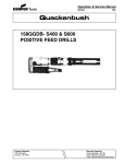
Geared Piston Air Motor AGP
Installation Manual
Introduction
This manual is valid for all Armak Geared Piston Air
Motors and may possibly not be valid in all respects
for the motor to be serviced.
In all questions concerning service or repair please
state besides the component part number the motor
type, its serial number or the year supplied. Data
concerning motor power, torque, allowable speeds,
air consumption or shaft loads permitted can be
found in the data sheet of the relevant Armak Motor.
Paint: standard is black primer or as specified.
1
2
Operating Limits
Armak Geared Piston Motors AGP do have
operating limits, which must be observed to
assure safe and reliable operation.
Operating limits are stated in section 2 below.
Armak Air Motors must never be test run off
load on their own as this may cause bearing
failure.
The pressure difference between inlet and
outlet determines the max. motor torque. The
air supply in combination with system pressure
determines the motor speed and power.
When operating air motors at full power, a
sudden drop in torque results in a sudden
speed increase above allowable limits if the
same air flow is continued. Equipment failure
might be the result. Wherever such condition
may occur, the exit air volume must be
restricted.
Valves mounted on the motor should have the
exhaust opening facing down. Reason: after
longer motor operation there could be ice
formed in the exhaust. When this ice melts, in
an upward facing valve water could enter valve
and motor, causing corrosion.
Installation and operating limits
In order to ensure the best performance and
life from these motors it is essential that the
following points are strictly observed.
These motors may be operated in any attitude,
provided adequate airline lubrication is supplied
(section 8). Being totally enclosed they can be
used in any environment within the ambient
temperature limits of -10OC to + 80OC.
Max. inlet air temperature is 65°C.
Maximum working pressure 8 bar (120 PSI).
Max. speed (max 5 minutes per hour)
is 1,15 x ncontinuous
AGP16 / AGP510 pmax 1300 min-1 ncont. 1800
AGP10 / AGP410 pmax 1100 min-1 ncont. 1800
AGP07 / AGP310 pmax 1600 min-1 ncont. 2000
AGP04 / AGP210 pmax 2200 min-1 ncont. 2500
AGP02
- pmax 2300 min-1 ncont 2500
AGP01 / AGP110 pmax 2200 min-1 ncont. 2500
Armak GmbH - Motoren
Enzstr.39 D-70806 Kornwestheim
Geschäftsführer Wolf Krisch
page 1 of 2
P
Maintenance or repair: we recommend to have this
done by your local Armak representative or by
Armak.
Warranty: no claims can be accepted for motors
opened, manipulated or repaired by third parties
without our written prior consent.
All warranty is restricted to actual replacement of
damaged components and requires motor operation
according to the design values for speed and
pressure and air supply given in all datasheets.
Direction of rotation section 9.
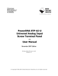
Motor shaft - permissible loads
AGP01 / -02 AGP07 AGP10 AGP16
/04/ 110 / 210 / -310 / -410 / -510
R
2.000
10.000 15.000 15.000
A
20
100
100
100
R radial force in middle of shaft - N
A axial force on shaft - N
Motor AGP10 and AGP16 with key-and-keyway
shaft ("F" type) is for chain or belt drive only.
Motor AGP16 / AGP10 with internal spline
("V" type) is for mounting on gears, brakes or
machinery using shaft extensions 117-048,
117-065, 117-066. This is to prevent bearing
damage due to incorrect or non aligned
mounting of equipment.
4
Prior to any installation or prior to first start
up blow air through the piping system to
remove debris remaining from the installation.
Spray some Kluber - Klubersynth MZ 4-17 or
similar anti corrosion into the motor air inlet
prior to connecting the motor.
Remove silencers prior to first start up and let
the motor run briefly without silencer so that any
remaining oil or rust preventive in the system
will not clog the silencer.
5
Air supply
Clean and dry air is required. A filter-regulatorlubricator must be installed as close to the
motor and its control valve as possible.
FRL with 15 bar inlet pressure and 1 to 8 bar
outlet pressure are recommended with 45
filter.
6
Piping
Motor performance data can only be achieved if
piping and smallest valve cross sections are
equal or larger than motor inlet cross sections
for piping lengths up to 3 m or larger for longer
lines. Piping lines should have an upwards
incline towards the motor and should have a
water drain at the lowest point.
Valves must be mounted on or near the Motor.
7
Silencers
have great effect on motor performance due to
3
Fon +49 7154 82400
Fax +49 7154 824080
HRB 207012 Stuttgart
www.armak-motor.de
[email protected]
ID-Nr DE814130032
a6204-m-AGPban-n-e-ar 1425
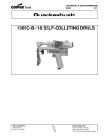
Geared Piston Air Motor AGP
Installation Manual
the back pressure generated in the silencer.
Silencers must be selected such that under no
conditions will they be closed due to ice forming
under operation.
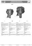
8
9.
Airline connection / Lubrication
The FRL must be regularly checked, water
drained off and filters changed. The lubricator
should be set as follows - drops per minute.
Motor
constant
interduty
mittent
AGP01 / AGP110
3-4
6-8
AGP02
3-4
6–8
AGP04 / AGP210
4-5
9 - 10
AGP07 / AGP310
6–8
10 - 12
AGP10 / AGP410
10 – 12
12 - 16
AGP16 / AGP510
10 - 12
12 - 16
Recommended Airline Lubricants for normal
ambient temperatures 0oC to 32oC.
Kluber - Summit Hysyn FG or similar.
For extremes of ambient temperature consult
the Armak
Fault finding
Armak Geared Piston Motors are designed for
rugged continuous duty. Interruptions in most
cases are due to the following errors.
10.1 Missing air line lubrication
will result in wear on the gears. Check the FRL.
10.2 Fault in air supply
If the motor power is too low, frequently the
reasons are:
10.3 air line cross sections too small and / or lines
too long for cross section installed
10.4 internal valve cross section too small
10.5 throttle at air outlet
10.6 silencer too small or iced or closed due to dirt
Armak GmbH - Motoren
Enzstr.39 D-70806 Kornwestheim
Geschäftsführer Wolf Krisch
page 2 of 2
11 Motor does not start
11.1 Motor too small for duty
11.2 errors in air supply - section 2, 4, 5 and 8
11.3 mechanical fault in system.
11.4 torque increase due to a change in application
12.1 Repair
Due to the extremely small tolerances in the
motor design, special care must be taken in
disassembly and reassembly. Errors can
reduce the motor power by up to 20%. We do
recommend to have service and repair done
by your Armak distributor.
In case it must be done locally, make sure that
prior instruction has been obtained, e.g. by
video. Stripping or repair without prior
confirmation by Armak or the Armak distributor
invalidates the warranty.
12.2 Disassembly
Without prior training Armak motors should not
be disassembled. Information for disassembly
of motors is not part of this manual.
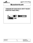
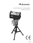
Motor rotation and airline connection
Port A = left when looking onto shaft
Motor turns ACW looking onto shaft
Port B = right when looking onto shaft:
Motor turns CW looking onto shaft
10
10.7 insufficient air volume
10.8 airline pressure too low
10.9 filters too small or clogged
12.3 Reassembly
As for disassembly we do not recommend a
reassembly of motors without prior training.
Information for reassembly of motors is not part
of this manual.
13
Long time storage
If motors are not operated over longer periods
or put into storage, motors must be preserved.
Fill in 2- 4 ccm of Kluber - Klubersynth MZ 4-17
or similar anti corrosion and rotate the motor
shaft to distribute oil inside the motor.
For very long time storage more oil should be
used and the motor shaft rotated a few times at
least every 3 months.
Fon +49 7154 82400
Fax +49 7154 824080
HRB 207012 Stuttgart
www.armak-motor.de
[email protected]
ID-Nr DE814130032
a6204-m-AGPban-n-e-ar 1425