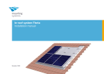
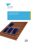
1
Open terrain system Sigma I
Installation manual
810-0017
Table of content
ENGLISH
Table of content
1
2
Joining the frame rails
8
Fitting laminates
Fitting the laminate clamps
Fixing the laminates
9
9
9
1.1
Short description
1.2
Intended use
2
1.3
Standards and technical directives
2
1.4
About this manual
2
Safety
3
2.1
Basic safety instructions
3
2.2
Warnings
3
2.3
Responsibilities of the owner/operator
3
Important installation instructions
4
3.1
Operating conditions
4
3.2
Preparation for installation
4
4
System overview
5
5
Install the system
6
5.1
Installation procedure
6
5.2
Quickstone and X-Stone
Installing the Quickstone
6
6
Installing the frame parts
Sinking posts into the ground
Fitting the adapter to the posts
Fitting the base rail
7
7
7
7
2
3
Sigma I
Introduction
Installation manual
5.5
6
Fitting framed modules
Fixing the outer modules of each row
Fixing the inner modules of each row
10
10
10
Specifications
11
1
1 Introduction
Introduction
1.1
Short description
ENGLISH
1
1.1 Short description
Sigma I is a mounting system for installing photovoltaic
elements on open areas. It was developed for laminates
and framed modules*.
The system is made of extruded aluminium and galvanised steel which means that it requires little maintenance. The use of Quickstones makes installation simple
and secure.
1.3
|
DIN 18800: Design and construction of steel
structures
|
DIN 1055, EUROCODE 9: Action on structures
|
|
|
1.4
Intended use
voltaic laminates and modules. Any other use is deemed
not to be as intended.
Intended use also includes compliance with the specifications stated in this installation manual. Mounting
Systems shall not be held liable for damages arising
from a failure to observe and follow the installation
manual, particularly the safety instructions, or from any
improper use of the product.
Item numbers
complies with the following standards:
Sigma satisfies guidelines and standards valid at the
time of delivery, is up to date with current technology
and complies with recognised safety-related regulations.
1.2
Standards and technical directives
Part 1: Densities and weights of building materials, structural elements and stored materials
Part 4: Wind loads (on structures which are not
susceptible to vibration)
Part 5: Snow loads and ice loads
(1)
(2)
Step-by-step procedure
Headers
Footers
About this manual
Pictograph
Subject of this manual
The subject of this manual is the installation of the open
terrain system Sigma .
Denotes background and additional information for step-by-step procedures.
The manual describes the installation of a module. Other
modules or laminates can be installed in the same way.
Specifications for the Sigma
the last chapter.
system can be found in
User group
Signposts
*
When ordering framed modules, please remember to include the appropriate module (end) clamps. For enquiries and custom designs, please
contact the Mounting Systems service department (telephone number
PTO).
Sigma I
Installation manual
2
Safety
2
Safety
2.1
Basic safety instructions
2.1 Basic safety instructions
DANGER
Denotes an immediately hazardous situation,
failure to observe which could lead to serious
injury or death.
WARNING
regulations of the Employer’s Liability Insurance
Association.
|
Comply with the relevant safety regulations.
|
The presence of a second party who can provide
help in the event of an accident is obligatory during
the entire installation process.
|
Keep a copy of this installation manual in the
immediate vicinity of the system.
Warnings
Sigma
(see Chapter 3.1, page 4) are observed. Mounting
Systems is not liable for damage occuring when
these conditions are not adhered to.
|
Ensure the durability of all connections and the
attachment of the system.
|
Ensure that suitable lifting gear is used for installation.
|
Ensure that only Mounting Systems components are
used when parts need to be replaced. Otherwise any
warranty claim is null and void.
WARNING
CAUTION
CAUTION
Responsibilities of the owner/operator
3
Important installation instructions
3
3.1 Operating conditions
Important installation instructions
Operating conditions
Snow load: 0,8 kN/m² maximum
|
Wind load: 25 m/s maximum
The prevailing statics must be checked for
each site. If stresses are higher, it may be
possible to adapt the system. For more
detailed information, please contact the
Mounting Systems service department
or a local structural engineer.
The ground at the site of the proposed installation must
be suitable for the use of foundation posts (Sigma
posts). A project-related assessment report on the
ground from an expert assessor and pull-out tests are
required. The project-related ground assessment report
will reveal the necessary anchoring depth and any
change required in the distance between the posts.
Regarding the anchoring depth make sure that
there is a distance of at least 50 cm between
the cables of the laminates/modules and the
ground. This avoids damages by animals.
Preparation for installation
The following tools are required to install the Sigma
system:
|
Allen key, 6 mm
|
Open-end spanner or socket, WAF 13
|
Two open-ended spanners or sockets, WAF 17
Sigma
4
System overview
4
System overview
(1)
Connection box for cable
Laminate (end) clamp
(2)
(2a)
Inter-module clamps and module end clamps for
framed modules
(3)
Laminate
(4)
Base rail
(3)
(5)
Anti-slip protection, only for laminates
(4)
(6)
Foundation posts
(7)
Adapter, pre-assembled, comprising
| Adapter plate
| Cherron
| 2x X-Stones
(7)
(2a)
Sigma
(6)
(5)
5
5
Installing the system
5.1
Installation procedure
5.2
Quickstone and X-Stone
Element to be fixed (e.g. module clamp)
Allen bolt
Quickstone
Base rail
X-Stones are used. These consist of an aluminium block
with two pre-assembled Quickstones.
Horizontal base rail
X-Stone with 2 Quickstones
Vertical base rail
Installing the X-Stone
Installing the Quickstone
Material damage through faulty installation
CAUTION
Incorrectly installed Quickstone connections
can rip out of the profile.
|
Install all Quickstone connections as
described below.
|
Install both Quickstones as described above.
|
Make sure that the upper rail lays flat on the lower
one.
|
Tighten both Quickstones completely only when you
have put the rails in their final position.
Installation
|
If necessary, adjust the bolt so that it does not protrude the Quickstone.
|
Fit the Quickstone from above into the profile channel so that it wedges underneath the protruding rail
hooks. When fitted correctly, the Quickstone
matches the form of the profile exactly.
|
Tighten the bolt with a torque of 8 Nm.
6
ENGLISH
Sinking posts into the ground
Chevron
Adapterplate
Small parts
X-Stone
Post
Fitting the adapter to the posts
The adapter is delivered pre-assembled and
comprises adapterplate, chevron and
2 X-Stones.
|
|
|
Hold the adapter up to the post so that the post is
positioned between the two angle brackets and the
open side of the Sigma profile rests against the
adapter.
Screw the adapter angle brackets to the post with the
hexagon head bolts (2x M10 x 140 mm), washers (4x
M10), spring washers (2x M10) and nuts (2x M10)
(tightening torque 17 Nm).
Cherron
X-Stone
Base rail
Fitting the base rails
Base rails of different lengths can be used alternately on
the Sigma system.
You will find the fitting sequence in your planning documents.
|
Lay the base rails upright onto the chevrons. Please
find the planned projection in your planning documents.
|
Fully hook the base rail into the Quickstone on the
X-Stone (see Chapter 5.1, page 6)
|
Tighten the Allen bolt to fasten the base rail
(Tightening torque 10 Nm).
|
Repeat steps 1 to 3 for the opposite rail.
Repeat the two described steps for all other posts.
7
Base rail
Splice with 2 Quickstones
Base rail
Connecting the base rails
8
Fitting laminates
Fitting laminates
Laminate breakage
CAUTION
Material damage through faulty installation
CAUTION
Fitting the laminate end clamps
Fixing the laminates
Sigma
9
Module end-clamp with Quickstone
Module
Base rail
Installation:
ENGLISH
Fixing the outer modules of each row
Fixing the inner modules of each row
Inter-module clamp with Quickstone
Module
Base rail
Installation:
10
Specifications
ENGLISH
6
Ground
a
Max. 25 m/s
Snow loada
Max. 0.8 kN/m2
Laminates/modules
Unframed and framed
In a row, up to approx. 10 m for unframed modules and 12 m for framed modules per unit
Portrait
b
Standard pitch 25° and 30°
Standard distance 70 cm, customer-specific heights possible on request
c
Dependent on type of laminate or module and local conditions.
d
Materials
Frame section: extruded aluminium, EN AW 6063 T66, adaptor plate annodised
Sigma
- posts: galvanised steel
Small parts: stainless steel (V2A)
Natural extruded aluminium
a.
b.
c.
d.
The prevailing statics must be checked for each site. For more detailed information, please contact the Mounting Systems service department during the initial stage of our planning
(contact PTO).
For further information, please contact the Mounting Systems service department during the initial stage of your planning (contact PTO).
A project-related assessment report on the ground needs to be handed in as a basis for the calculation of the specific distances. For further information, please contact the Mounting Systems
service department during the initial stage of your planning (contact PTO).
The ramming depth will be calculated during the planning stage of the project on the basis of the ground assessment report and the project specifics. However, the thus calculated result must
be double-checked on-site by way of pull-out tests.
SOLFEX LTD
UNITS 3 - 5 CHARNLEY FOLD INDUSTRIAL ESTATE
BAMBER BRIDGE
PRESTON
LANCASHIRE
PR5 6PS
U.K.
TEL: 00 44 (0) 1772 312847
E-MAIL: [email protected]
WEBSITE: www.solfex.co.uk
Subject to technical alterations