1
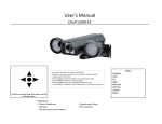
Motorcycle
Electronic Cruise Control
Installation Manual
For
KAWASAKI Z1000 GTR
Concours
6 August, 1999
Manufactured by MotorCycle Setup Pty. Ltd.
7 Moritz Street, Box Hill, Victoria, AUSTRALIA, 3128
Kawasaki Z1000 GTR -all models ©
MotorCycle Setup Pty. Ltd.
Electronic Cruise Control Installation Manual ©
To suit Kawasaki Z1000 GTR
Your electronic cruise control has been adapted from an Australian designed, automotive cruise control
specifically to suit your motorcycle. Months of testing have resulted in changes to the electronic
circuitry to deliver safe, reliable operation on the motorcycle models listed above. It is essential that you
install the correct kit to your motorcycle and follow the installation instructions precisely so that
electrical interference does not cause the unit to behave erratically or be rendered inoperative.
WE STRONGLY RECOMMEND AGAINST FITTING OFF-THE-SHELF MOTOR CAR CRUISE
CONTROLS TO ANY MOTORCYCLE!
If, after reading these instructions, you feel you are not competent to install this kit, we strongly urge you
to seek the assistance of one of our authorised dealers and installers. Please phone or email us to obtain
the name of your nearest outlet. A list will also be available soon on our ‘web page’ http://www.mccruise.com.
Note: - California specification motorcycles.
California spec motorcycles have an emissions control canister under the right side cover that occupies
the space used by the cruise control actuator. As a result it is not possible to fit the cruise control to this
motorcycle unless the canister is relocated. Relocation of the canister is the owner’s responsibility and
has not been considered in the design for installation on this motorcycle.
CONTENTS
1. INTRODUCTION
2. WARNINGS, CAUTIONS AND NOTES
3. TOOLS REQUIRED
4. PARTS LIST
5. OVERVIEW OF CRUISE CONTROL OPERATION
6. PREPARING THE BIKE FOR CRUISE CONTROL INSTALLATION
7. INSTALLATION
8. DIAGNOSTIC MODE OPERATION
9. MANUAL ADJUSTMENTS TO THE BRAKE PEDAL AND FRONT BRAKE LEVER
10.OPERATING INSTRUCTIONS
11.SAFETY ISSUES & FEATURES
12. ROAD TEST AND ADJUSTMENTS
13. TROUBLE SHOOTING, TESTING & SELF DIAGNOSTICS
14. RIDING TIPS
2
Kawasaki Z1000 GTR -all models ©
1.
INTRODUCTION
Congratulations, you have purchased one of the most advanced cruise control systems in the world - and the
first after-market electronic cruise control kit adapted to motorcycles. All functions are microprocessor
controlled, which reduces the complexity of installation.
Before installing your cruise control, take the time to read and understand each installation step in this manual.
Several steps are dependent on others, so it is important know where and how each component is to be mounted
before installation commences.
Your kit has been designed for a specific motorcycle. Even if you have installed kits before, take note of where
and how components should be installed - particularly the wiring harness layout and connections.
2.
WARNINGS, CAUTIONS and NOTES
This manual contains several cautions, warnings and notes, which are prominently displayed. The convention
used is:
A warning applies whenever injury could result from ignoring the warning;
A caution applies whenever damage to the bike or cruise control could result from ignoring the caution;
and
A note applies where other aspects should be considered before any action to do with installation is
undertaken.
EXAMPLES:
WARNING:
Always ensure the bike is properly supported on the side or centre stand and cannot
accidentally fall off either stand.
CAUTION:
Before drilling any holes, make sure there are no components that may be damaged
on the other side of the surface being drilled. Double check for any wiring harness
which might be easily damaged by a drill bit.
NOTE:
Do not tighten any cable ties locating the wiring harness until all cable ties are in
place and all connections are complete.
3.
•
•
•
•
TOOLS REQUIRED
A tool kit containing appropriate metric spanners and screwdrivers;
Loctite ‘243 or 222’ or equivalent;
A 5mm.hex key;
A 1/4" or3/8" drive metric socket set with sizes down to 8mm is recommended.
3
Kawasaki Z1000 GTR -all models ©
4.
PARTS LIST
Check that all components depicted in the parts list at the rear of this manual are included in the cruise control
kit. Please phone (03) 9808 2804 within Australia, international (61 3) 9808 2804 or fax (61 3) 9808 2445 or
email at [email protected] for advice, if any parts are missing;
5.
OVERVIEW OF CRUISE CONTROL OPERATION
The principles behind your cruise control's operation are very simple:
•
The computer continuously monitors the frequency of electrical pulses generated by magnets
passing the sensor;
•
When the SET key on the switch is pressed the computer stores the pulse frequency at the time in
memory and then continuously adjusts the vacuum actuator, which controls the carburettors to
maintain the pulse frequency at the same figure to which it was set. If the frequency drops below
the set frequency, the computer applies more throttle. If the frequency is above the set frequency,
the computer turns the throttle off. The key is that the computer monitors and reacts to changes very
quickly and smoothly so that the speed effectively remains nearly constant.
There are seven major components in your kit: the computer, the vacuum actuator, the cable interface unit, the
speed sensor, the switch, the electronic clutch switch and the loom. The functions of each are described below:
•
•
•
•
•
•
•
the computer - monitors road speed, adjusts the throttle by controlling the vacuum actuator &
monitors the switch and brake system for instructions from these components;
the vacuum actuator - controls the carburettors by pulling or releasing a cable which attaches to the
carburettors via the cable interface unit (CIU);
the CIU - translates the motion from the throttle grip and the vacuum actuator to the carburettors via
a new cable supplied in the kit;
the speed sensor - generates electrical pulses when the bike is in motion;
the switch - sends instructions from the rider to the computer;
the electronic clutch switch (ECS) – monitors engine speed and disengages the cruise if the clutch is
disengaged; and
the electrical loom - which connects the switch, the computer, the vacuum actuator, the sensor, the
ECS and the brake system.
The cable interface unit is a new component developed and patented by MotorCycle Setup and is the key to
safe cruise control operation on motorcycles. An understanding of how it works should help you avoid making
mistakes during installation.
The following diagrams show the basic assembly procedure and operating principles of the cruise control Cable
Interface Unit (CIU). The actual entry points of cables and the direction of rotation may differ depending on
the model of the motor cycle, but the principles involved remain the same. Specific assembly instructions are
provided later within this manual.
In order to improve the clarity of the diagrams, the multiple holes in the dual spool have been omitted, with
only the actual holes used for the cable nipples being shown.
4
Kawasaki Z1000 GTR -all models ©
1st step.
The actuator spool is installed in the CIU housing
with the actuator cable. The actuator spool is
rotated to fully extend the cable.
Actuator cable
CIU housing
Actuator spool
Bush
2nd step.
The dual spool and carburettor cable are installed.
The carburettor cable is attached to the lower
groove in the dual spool. The other end of the
carburettor cable is attached to the carburettors.
Roll pin in dual spool
Dual spool
Carburettor cable
Note the position of the roll pin. It is nearly
contacting the end of the groove in the actuator
spool. The free play in the carburettor cable must
be adjusted so that the cable outer can be pulled
out 2 ~ 3mm before the carburettors start to open.
This ensures that the cruise control cannot prevent
the carburettors returning to idle. If more free play
is allowed the response of the cruise control is
compromised.
2 ~ 3 mm
This adjustment of free play is usually performed
after final assembly of the CIU is completed and
the CIU is in its final location. This is because flexing the cable affects the free play. It is shown at this stage
in these diagrams to improve clarity.
After this adjustment is performed, the carburettor cable adjustment MUST NOT BE MOVED. All future
adjustments of free play in the throttle must be performed on the throttle cable from the throttle grip. If
incorrect free play in the carburettor cable is suspected due to inconsistent cruise operation or because of
inconsistent idle speed, the adjusters on the throttle cable from the hand grip must be backed all the way off to
give as much free play as possible. If this does not result in AT LEAST 5mm of free play in the throttle cable,
the throttle cable must be removed from the hand grip or CIU before adjustment of the carburettor cable is
attempted. This is crucial because the amount of free play in the throttle cable also affects the apparent free
play in the carburettor cable.
5
Kawasaki Z1000 GTR -all models ©
3rd step
The throttle cable is installed. The throttle cable is
attached in the upper groove in the dual spool.
Throttle grip cable
Normally the end cap and retaining nut would be
installed at this point. These items are not shown
in order to improve clarity.
Dual spool
Normal throttle operation
During normal operation of the throttle,
the throttle cable is pulled by twisting the
throttle grip. This pulls on the dual spool
and rotates it, thus pulling the carburettor
cable and opening the carburettors.
Throttle grip is twisted pulling cable
Roll pin in dual spool is free to move
in the groove in the actuator spool
Because the roll pin is free to move in the
groove in the actuator spool, this spool
does not move. This reduces friction in
the throttle system and prevents any
possibility of jamming due to cables
buckling when being pushed.
Carburettor cable opens carburettors
Actuator spool does not move
Cruise operation
During cruise operation the actuator cable
pulls the actuator spool and rotates it.
The end of the groove contacts the roll
pin in the carburettor spool, rotating the
spool and pulling the carburettor cable.
Roll pin in dual spool is pulled around by the end
of the groove in the actuator spool
Actuator cable is pulled by actuator
Throttle cable is pulled by the closing cable
via the twist grip
When the carburettors open the closing
cable on the carburettors is pulled. This
results in the twist grip rotating, once all
the free play is taken out of all the cables.
As a result, the rider will notice the twist
grip moving while the cruise is operating.
Carburettor cable opens carburettors
Both spools rotate
It is possible to roll the throttle off by hand, thus opposing the cruise control actuator. As this will result in a
loss of speed the cruise control computer will ‘read’ this as the bike going up an incline, and attempt to apply
more throttle. If the twist grip is released again, it is possible for the throttle to go immediately to full throttle.
While the throttle will back off again as soon as the set speed is reached or if the rate of acceleration exceeds
6
Kawasaki Z1000 GTR -all models ©
the cruise controls preset rate (1 ~ 2 km/h gain in speed per second), the initial acceleration could be quite
violent. As a result, we do not recommend manually forcing the throttle off while the cruise control is engaged.
If the throttle grip is twisted open while the cruise control is engaged the cruise control is over ridden by the
rider. When the throttle is released, the cruise control will resume control, unless it has been disengaged by
brake operation or if the motor cycle exceeds the current set speed by 150% such as during an overtaking
manoeuvre. The cruise will also disengage if the speed drops to 75% of set speed such as when riding up hill.
This is unlikely to occur on large capacity motorcycles.
6.
PREPARING THE BIKE FOR CRUISE CONTROL INSTALLATION
Remove the following items from the bike:
•
•
•
•
the seat;
the petrol tank;
the RHS side cover;
the tool kit and the battery cover.
LUBRICATING THE THROTTLE GRIP – this is essential maintenance.
•
•
•
•
•
7.
Remove the two screws which mount the throttle switch block;
Pull the two halves of the switch block apart;
Remove the cable nipples from the handgrip and the RHS handlebar weight. Slide the handgrip off
the bar;
Run 6 drops of light oil - eg sewing machine oil (not engine oil) down each throttle cable;
Apply a thin film of engine oil to the handlebar and re-install the handgrip and switch block.
INSTALLATION
The main components to be installed include the wiring loom, the cable interface unit, the vacuum actuator
that controls the carburettor via the cable interface unit, the computer, the speed sensor and the switch.
Installing components in the following order has been found to be the most efficient.
7.1
INSTALLING THE CRUISE CONTROL SWITCH
•
Remove the cap screws from the clutch master cylinder
mounting clamp on the handlebar (LHS);
•
Remove the clamp bracket from the handlebar and use a file,
grinder or sandpaper on a flat surface to remove material
equivalent to about ½ the thickness of the switch mounting
bracket from the lower face of the clamp;
7
Kawasaki Z1000 GTR -all models ©
•
Noting the ‘up’ arrow on the clamp, put the top bolt into the
clamp, then the bottom bolt through the clamp and switch
bracket;
Screw the cap screws into the master cylinder using a 5mm
hex key and position the master cylinder and clutch lever in
the correct position. Tighten the bottom cap screw, then the
top one;
•
Run the switch
wire down the
handlebar with
the existing loom using cable ties, then backwards with the
choke cable, until it rests in the centre of the bike above the
carburettors. The plug will be connected later.
NOTE: The picture depicts the switch wire position above the
LHS ignition coil (fingers at right of photo) and the final
position of the throttle cable to be re-located later (fingers at left
of photo). Note the switch wire should run UNDER the rear
coil mounting lug.
7.2
•
•
•
7.3
•
•
•
7.4
•
INSTALLING THE COMPUTER
Clean the rear mudguard behind the battery with methylated
spirits (wood alcohol) on a cloth;
Clean the underside of the computer as well;
Apply two of the self-adhesive pads lengthwise to the
underside of the computer and press the computer firmly
against the mudguard until it sticks firmly. Be careful to
keep the computer vertical when applying it to the mudguard
- it cannot be moved once the pads touch the mudguard.
INSTALLING THE ACTUATOR
Thread the actuator cable forward behind the RHS vertical
frame rail in front of the battery box, over the RHS rear of
the crankcase, up to the left side of the rocker box (cam
cover) and lay the end on the RHS front rocker box until
later;
Slide the actuator bracket down in the recess in the RHS of
the battery box until the actuator bracket rests firmly on the
plastic lip;
Use a cable tie to attach the cable at the end of the actuator to
the vertical frame rail to hold the actuator in place.
INSTALLING THE VACUUM HOSE
Attach the vacuum hose supplied to one of the RHS
carburettors vacuum balance port. The photo shows the
location of the balance port on the USA version of the bike.
Install the hose with the black end of the one-way valve
closest to the carburettors;
8
Kawasaki Z1000 GTR -all models ©
•
7.5
•
•
•
Thread the hose backwards over the carburettors under the frame rail initially then above the frame rail
above the airbox. Continue running the hose downwards under the front of the actuator, as shown in the
photograph, and attach it to the actuator.
INSTALLING THE CABLE INTERFACE UNIT (CIU)
Back-off the cable adjuster at the throttle grip all the way;
Disconnect the opening throttle cable – the rear cable on the
carburettors;
Withdraw the opening cable from the carburettors. Re-route
the cable so that it runs around the outside of the LHS coil
above the rear rocker box and inside the left frame tube
(between the frame tube and the coil).
•
•
•
•
The end of the throttle cable should terminate above the rear
RHS rocker box;
Run the first lock nut on the throttle cable to the top of the
adjuster and tighten it gently. Run the second lock nut up the
adjuster, but do not tighten;
Loosen the lock nuts on the closing cable adjuster at the
carburettors:
Screw the top lock nut all the way up the adjuster and run the
bottom lock nut down the adjuster within two or three threads
of the end of the adjuster;
NOTE: the next step is very tricky. Sometimes the nipple falls
into place and other times you just have to be persistent. If you find you can't re-install the nipple, remove a
maximum of 2mm off each end of the nipple with a file, taking care not to distort the cylindrical shape of the
nipple - and try again. We find a long thin screw driver, an old hacksaw blade, two people and lots of light help
enormously!
•
•
Install the cylindrical nipple on the new carburettor cable supplied in the kit on the carburettor spindle
where the original throttle cable attached. Lock up the nuts on the adjuster so that it is about mid-way on
the threaded adjustment; be careful not to over tighten the lock nuts. The adjusters are made of brass and
can be broken if over tightened. If desired, a drop of low strength thread locker such as Loctite 222 can be
applied to the threads before installation.
Run the carburettor cable forward to the left of the choke cable and the thermostat, then to the RHS of the
bike above the rocker box (camshaft cover);
NOTE: If the carburettor spindle is stiff, spray the carburettor spindle mechanism with a suitable lubricant.
Silicon or Teflon sprays are recommended. De-watering fluids such as WD40 or CRC 5-56 are not
recommended as they may attract dust.
9
Kawasaki Z1000 GTR -all models ©
•
Insert the throttle cable in the slot in the CIU and rotate the
CIU onto the throttle cable adjuster. Note that the adjuster is
fixed to the cable, so the CIU must rotate. Thread the
adjuster into the CIU until the end is level with the inside
wall of the CIU, then gently tighten the lock nut with the
CIU temporarily above the right rear rocker box;
•
•
Insert the ball nipple on the actuator cable into the actuator
spool and locate the spool in the CIU with the semi-circular
groove facing upwards. Rotate the spool anti-clockwise to
fully extend the cable;
•
•
•
•
•
Insert the actuator
cable into the unthreaded hole in the CIU with the retaining
screw in it. Apply Loctite 222 or 243 to the screw and tighten it
gently to retain the cable in the CIU. CAUTION: Take care not
to squeeze the cable outer with the screw so that the inner cable
jams. Check this by sliding the actuator cable in and out by
hand while carefully locking the outer cable with the retaining
screw;
Insert the ball nipple on the carburettor cable into the last
threaded hole and screw the adjuster all the way in;
Locate the ball nipple in the marked hole in the roll-pin side
of the dual spool and place the dual spool in the CIU so that
the roll-pin engages in the groove in the actuator spool;
Place the nipple on the throttle cable in the marked hole in
the top of the dual spool;
Insert the bush into the two spools;
Place a flat washer on the 5mm bolt. Install it in the hole in
from the bottom of the CIU.
•
Install the endcap on the top of the CIU;
•
Place a flat washer on the bolt and install the Nyloc nut on the top of the CIU, but do not tighten yet;
10
Kawasaki Z1000 GTR -all models ©
•
Adjust the carburettor cable to give 2-3mm free movement
between the outer cable and the adjuster - see photo. Lock up
the adjuster;
WARNING: THE PROCEDURE JUST DESCRIBED CONTROLS THE FREE PLAY BETWEEN
THE CRUISE CONTROL AND THE CARBURETTORS. THE ADJUSTERS SHOULD NOT BE
MOVED AFTER THIS INITIAL SETTING. ANY FUTURE ADJUSTMENT OF THROTTLE GRIP
FREEPLAY MUST BE DONE ONLY WITH THE CABLE ADJUSTERS AT THE THROTTLE GRIP
END OF THE CABLES, NOT THE CARBURETTOR CABLE ADJUSTERS. THIS POINT MUST BE
STRESSED TO THE OWNER.
•
Install the CIU
mounting bracket
as shown in the
photos. Position
the curved sections
of the bracket on
the frame rail as far
forward as possible
with the leading
edge against the
frame gusset.
•
Remove the nut and
washer from the top
of the CIU through
bolt and mount it
on the bracket as
shown with the
washer and nut on
top of the bracket.
Position the bracket
so the CIU will not
touch the rocker box or spark plug cap and is not so high that it will touch the petrol tank and rub a hole in
it.
•
Use side-cutters or tin snips to cut off the excess length in the hose clamps so that they will not rub
holes in the petrol tank.
11
Kawasaki Z1000 GTR -all models ©
•
•
•
•
7.6
Squeeze a little silicone sealant, such as Silastic, into the slot in the CIU where the throttle cable was
installed to seal the CIU from dust and water;
Set the adjuster at the throttle grip mid-way in its adjustment
range;
Adjust the free play in the throttle grip using the adjuster at
the carburettors on the closing cable to suit your
requirements. Ensure the cables do not bind when the
handlebars are turned lock to lock. In future, fine
adjustments to the free play can be performed using the
adjuster at the throttle grip if required;
Finally, position the original throttle cable, which goes to the
CIU as shown in the photo and cable tie it to the frame rail.
INSTALLING THE SPEED SENSOR
•
Use a bolt with a magnet attached as shown in the photos to
place one of the magnets in a clean hex head hole in the rear
disk brake mounting bolt. Slide the bolt sideways to detach
the magnet from the bolt when in position in the Allen
screw;
•
Hold the other magnet close to the first one and determine
which end sticks to the magnet in the Allen screw. Note the
end which sticks and put this face into the diametrically
opposite allen screw in the disk, so the two magnets are equally spaced around the disk with the same 'pole'
facing outwards. It is vital that this procedure is followed correctly. If opposite poles face the sensor, the
cruise control will NOT work..
•
Remove the nut from the brake torque arm and install the
sensor mounting bracket as shown in the photo. Rotate the
bracket backwards until the sensor rests on the calliper
mount. Use Loctite 222 or 243 on the nut and ensure it is
tight.
•
Finally attach the sensor wires to the sensor when the loom is
installed and run the wire as per the instructions (see next
section for loom installation)
7.7
•
•
•
INSTALLING THE WIRING LOOM
Plug the 12 pin plug on the loom into the computer and feed the loom to the RHS of the bike behind the
battery box;
Connect the red, white and black actuator wires to the actuator;
Run the green earth lead back up inside the frame rail and plug it into the accessory earth (ground) plug
with the black/yellow wire (the black wire with the yellow trace) attached. The accessory earth plug is on
the rear mudguard (fender) behind the battery and tool kit and has provision for two bullet connectors.
Take care to select the correct plug. If you use the wrong one there will be a direct short circuit in the
electrical system;
12
Kawasaki Z1000 GTR -all models ©
•
•
•
•
•
•
•
7.8
•
Disconnect the two bullet connectors which join the bike main loom
wires to the rear brake switch;
Connect the two brown wires on the loom to the wires coming from the
brake switch;
Connect the red and orange wire on the cruise loom to the red/blue wire
(the red wire with the blue trace) on the bike's loom;
Connect the blue wire on the cruise control to the blue/red wire (the
blue wire with the red trace) on the bike's loom;
Run the speed sensor wire down to the brake line leading to the rear
brake and clip it onto the swing arm using the same clips as the brake
line. Cable tie it in place;
Attach the blue and black speed sensor wires to the speed sensor - it
doesn't matter which wire connects to which terminal;
Finally, run the switch wire below the actuator, up under the top frame
rail and forward under all frame rails and connect it to the four pin switch connector, which was previously
installed.
INSTALLING THE ELECTRONIC CLUTCH SWITCH (ECS)
How the ECS works.
The electronic clutch switch (ECS) is not a true switch, but is a device that monitors the rate of gain of engine
speed and also the absolute speed of the engine by monitoring ignition pulses. If the switch detects a rapid
increase in engine speed, such as when the clutch is disengaged while throttle is applied, the ECS will activate
and disengage the cruise control. The switch does not respond to a decrease in engine RPM. For example, if
the motorcycle is travelling down a hill with the cruise engaged and no throttle applied, and the clutch is
disengaged by the rider, the engine speed will drop to idle. The ECS will not disengage the cruise control.
When the speed of the bike drops to the set speed the cruise will apply throttle. Only when the engine speed
starts to increase will the ECS detect the change, and then disengage the cruise.
The switch will detect the engine speed increase and switch off the cruise by the time the engine has gained
1,000 ~ 2,000 RPM. How high the engine revs above the initial 1,000~2,000 depends on how much throttle the
cruise has applied at the time. If the throttle is open a significant amount, such as when travelling up a hill, the
time taken for the throttle to return to idle position may mean the engine gains a lot of revs when the clutch is
pulled in.
If the cruise has only applied a small amount of throttle the rate of change in the engine speed may be so slow
that the ECS will not detect it at all. The engine may reach redline or beyond if the rate is slow enough,
although this is unlikely. For this to occur the engine would have to take 5 seconds or more to go from idle to
redline. On high revving motorcycles (sports engines) the ECS should activate regardless before redline is
reached as the engine speed exceeds the inbuilt limits of the ECS.
•
Fitting the ECS
•
Locate the ignition coils. The pair of coils are under the fuel tank, mounted immediately behind the steering
head. Both coils have red wires going to them. One coil also has a green wire and the other has a black
wire going to it. Disconnect either the green wire or the black wire from its coil spade terminal, whichever
is easier.
13
Kawasaki Z1000 GTR -all models ©
•
Ensure the area where the ECS will be mounted is clean by wiping the mudguard with methylated spirits
before mounting the switch. Check to see that there is sufficient length in the wires to allow the switch to
mount where you want to put it. Mount the clutch switch on the rear mudguard, near the cruise control
computer using the self adhesive pad on the switch or screws through the tabs.
•
The clutch switch has four long wires coming out of it. Connect them as follows:
•
Route the orange and purple wire to the cruise control computer. Connect the plug on the wires to the
matching plug on the short leads from the computer plug.
•
The green earth wire with the eye connector should be
attached under the head of the bolt that holds the rear fairing
in place immediately behind the brake fluid reservoir (see
photo) or any other convenient 6mm bolt that will provide an
earth. Do not use the brake fluid reservoir mount as it is not
earthed.
•
The yellow ignition sensor wire should be run with the cruise
control loom forward until the coils are reached. Run the
wire to the coil terminals. Connect the terminal to the coil.
Place the previously disconnected wire from the coil on the piggy back spade connector.
•
Cable tie the ignition sensor wire to the cruise control loom in a few places. Ensure that all other wires are
routed neatly and cable tie if required.
Your cruise control is now ready for testing!
NOTE:
8.
After diagnostic testing, re-install the battery cover, fuel tank, the side cover and the seat.
DIAGNOSTIC MODE OPERATION
Your cruise control comes with a means of making it operate the throttle without the speed sensor detecting
movement. This is the best way to check that the electrical and mechanical operation of the cruise control is
working properly - excluding speed control circuits.
• Note:- During the diagnostic checks many of the features of the cruise control are confirmed by the LED
(light) on the computer operating. For example, brake switch operation is confirmed by the LED. The LED
only stays on for a few seconds with most operations. If the brake pedal is pushed, the LED will come on.
If the pedal is held after a few seconds the LED will go out. If the pedal is released and re-applied, the LED
will come back on, and then turn off after a few seconds. THIS IS NORMAL AND DOES NOT
INDICATE A FAULT IN THE SPEED CONTROL. This applies to most operations performed in
diagnostic mode.
14
Kawasaki Z1000 GTR -all models ©
•
•
•
•
•
•
•
•
•
•
•
•
Turn the cruise control ON/OFF switch to OFF;
Turn the ignition switch ON but DO NOT start the engine. Check that the kill switch is also ON.
Depress and hold the SET key while turning the cruise control ON;
Take your finger off the SET key;
Pull the front brake lever and depress the rear brake pedal a few times. The LED on the computer should
illuminate when EITHER lever is used. This indicates that the cruise control will cancel when the brakes are
applied. If the LED does not come on, the most likely cause is incorrect adjustment of the brake switches.
If either of the switches is adjusted so that it does not turn OFF at all, the light WILL NOT COME ON AT
ALL. It is then necessary to adjust the switch so that it turns OFF when the brake is released. IF THE
BRAKE SWITCH OPERATION IS NOT CONFIRMED BY THE LED OPERATING ON THE
COMPUTER NOTHING ELSE WILL WORK ON THE CRUISE CONTROL. See the next section.
Now tap the SET key once while listening for a click from the vacuum actuator and watching the red LED
on the front of the computer. You should hear the click and see the LED flash. Depress and hold the SET
key. The LED should come on and stay on while the SET key is depressed and regular clicks should be
heard from the actuator.
Now tap the RES key once while listening for a click from the vacuum actuator and watching the red LED
on the front of the computer. You should hear a slightly different sounding click and see the LED flash.
Depress and hold the RES key. The LED should come on and stay on while the RES key is depressed and
regular clicks should be heard from the actuator.
Turn the cruise control power switch OFF;
Start the bike in neutral;
Depress and hold the SET key while turning the cruise control ON;
Take your finger off the SET key;
Now tap the set key once while listening for a click from the vacuum actuator and watching the red LED on
the front of the computer. If you hear the click and see the LED flash, tap the SET key a few more times
until the revs start to rise. Depress the RES key and the revs will drop. Some delay occurs with these
operations.
CAUTION: You need to be careful not to tap the SET key too many times as it is easy to over-rev the
engine if you tap it too often. If the engine revs too fast quickly turn off the cruise control
switch OR the bike’s KILL switch. If the ECS (electronic clutch switch) is working
correctly it should protect the engine by shutting off the cruise control before such high
revolutions are reached;
CAUTION:
IT IS VERY EASY TO OVER-REV THE BIKE IN THE NEXT STEP - SO BE
CAREFUL!
• When you are sure single taps work, depress and hold the SET key for a couple of seconds and see if
multiple pulses are sent to the actuator. Listen for clicks and look at the LED.
Checking the speed sensor: With the cruise in diagnostic mode, put the bike on the centre stand with the
engine running, engage 4th or 5th gear and carefully accelerate the engine until the rear wheel is spinning at 60
or 70 kph (35~45 mph). Observe the LED on the computer to see it flashes regularly. It should flash quite
slowly at these speeds - at 1-2 second intervals.
Checking the ECS: With the cruise in diagnostic mode with the engine running, observe the red LED indicator
on the clutch switch and the LED on the computer. Quickly rev the engine by ‘blipping’ the throttle. The
LED’s should illuminate briefly as the engine reaches 2,000~3,000 RPM if the engine starts from idle.
15
Kawasaki Z1000 GTR -all models ©
The slower the rate of increase of revs, the higher the revs required to make the LED’s light. A quick blip
should resulting in the LED’s coming on at about 2,000~2,500 RPM. A slow increase in revs may not see the
LED’s coming on until 4,000 RPM or more. When the LED’s come on it indicates that the cruise control will
be cancelled. Remember, if the cruise is NOT in diagnostic mode, only the ECS LED will illuminate. The
cruise must be in diagnostic mode if the cruise computer LED is to illuminate too.
Using the bikes throttle raise the engine speed to the same revs that would be used at typical ‘cruising speed’ ie
about 100kph (60mph), typically 3500~4000 RPM. The LED on the ECS should come on. Hold the engine
speed constant. The LED should turn off after 5~20 seconds.
If the LED does not turn off after 30 seconds, the cruise control may not work and the sensitivity of the switch
may need to be adjusted. The adjustment procedure is described in Section 12, Road Test and Adjustments.
NOTE:
9.
Remember to wait at least 5 seconds after turning the cruise control off when in
diagnostic mode to then use it in cruise control mode – otherwise it stays in
diagnostic mode. It takes time for the capacitor which protects the computer from
surges in the power supply to discharge fully.
MANUAL ADJUSTMENTS TO THE BRAKE PEDAL AND FRONT BRAKE LEVER
Since the brakes are the fastest way to turn the cruise control off, it is ESSENTIAL that they be adjusted
optimally to suit the rider AND that they activate the rear brake lamp as quickly as possible. It is recommended
that both front and rear brakes be set up so that the brake lamp turns on as early as possible when either brake is
applied. Naturally you have to ensure that the brake lamp does turn off - otherwise the cruise control will not
work at all. Careful adjustment of the foot brake lever so that the rider's foot does not have to lift up to reach it
is recommended. Next, adjust the brake switch so that it turns on with very little movement of the brake pedal.
Repeat this process with the front brake lever.
It is recommended you adjust the rest position of the gear lever to the foot brake lever for optimum rider
comfort.
NOTE:
10.
IF THE REAR BRAKE LIGHT FILAMENT OR FUSE BREAKS, OR THE BRAKE
LIGHT IS ON, THE CRUISE CONTROL WILL NOT WORK AT ALL. IF YOUR
CRUISE CONTROL APPEARS NOT TO BE WORKING, THESE ARE THE FIRST
THINGS TO CHECK.
OPERATING INSTRUCTIONS
Although your cruise control has many sophisticated features, it has been designed to be very easy to operate.
Its operating range is from about 40kph (not recommended) to approximately 180kph (also NOT
recommended).
The cruise control operates by monitoring the road speed of the bike and uses a computer to maintain any ‘set’
speed within its operating range. The computer is instantly de-activated by either front or rear brake lever
pressure sufficient to turn on the brake lights.
All commands are input using the three switches on the switch block.
16
Kawasaki Z1000 GTR -all models ©
The functions performed by each key are as follows:
ON/OFF Switch
The OFF-ON switch is a slide switch and ‘enables’ the SET/ACC (Set/Accelerate) and RES/DEC
(Resume/Decelerate) keys when turned ON. The SET/ACC and RES/ACC switches are activated
by depressing them. Turning the OFF-ON switch OFF disables the cruise control.
SET key - maintains speed or produces acceleration
The SET key has four functions:
1. When the bike is in motion within the cruise control’s operating range, depressing and
releasing the SET key sets the computer to maintain the speed at the time the SET key was
depressed;
2. While the cruise control is controlling the bike’s speed, firmly but quickly tapping the SET
key increases the set speed by about 2kph for each tap. Six (6) taps in rapid succession
increases the set speed by approximately 10kph. Different bikes respond slightly differently.
Experiment until you find out precisely how your bike responds;
3. While the cruise control is controlling the bike’s speed, depressing and holding the SET key
results in the bike smoothly accelerating until the SET key is released (or until the bike
achieves the cruise control’s maximum operating speed - this is not recommended). The rate
at which acceleration takes place is a function of the power of the bike and the position of the
sensitivity switch [Refer to section 10] on the cruise computer;
4. Used in conjunction with the ON/OFF switch, it puts the cruise control in ‘diagnostic mode’.
While riding the bike, the cruise control can be set to a higher speed by:
a. Opening the throttle and pressing the ‘SET’ key after the required speed is reached;
b. Tapping the ‘SET’ key to progressively accelerate the bike;
c. Depressing and holding the ‘SET’ key until the required speed is reached.
RES key - resumes the previously set speed or produces deceleration.
1. If the cruise control has been controlling the bike’s speed and has been deactivated using the
brakes AND the cruise control or engine have not been turned off, depressing and releasing the
RES key causes the cruise control to return to its previously set speed;
2. If the cruise control is controlling the bike’s speed, tapping the RES key decelerates the bike by
approximately 2kph per tap;
3. If the cruise control is controlling the bike’s speed, depressing and holding the RES key down,
decelerates the bike until it is released or the bike slows beyond the cruise control’s operating
range. Releasing the key sets the computer to the current speed.
17
Kawasaki Z1000 GTR -all models ©
NOTE:
1.
If the bike’s speed drops below 75% of the SET speed, the cruise control deactivates
by itself. This could happen on a very steep incline, but is very uncommon on large
capacity bikes. If it does, simply accelerate using the throttle and SET the cruise control
again.
2.
If the bike’s speed increases to 150% of the SET speed, the cruise control
deactivates by itself. This can happen when accelerating to pass a car. If it does, simply
decelerate using the throttle and SET or RESume the cruise control again.
11.
SAFETY ISSUES & FEATURES
Electrical ‘Noise’.
Noise is a broad term used to describe the electromagnetic radiation of energy. Noise is generated during rapid
changes in voltage or current levels or by radio transmitters (ignition systems, alternators, mobile phones and
other heavy current carrying wires). If noise gets coupled into the cruise control wiring harness it can create
disturbances within the cruise control computer. The cruise control may drop out after engagement or not
engage at all, but still pass all diagnostic tests.
The most likely causes of electrical noise interference on a motorcycle is faulty spark plug leads or fitment of
non suppressed spark plug leads, or the electrical system could be in poor repair due to age or lack of
appropriate preventative maintenance.
WARNING: - It is ESSENTIAL that the spark plug leads are radio suppression type leads and that they
are in good condition. Inspect the spark plug leads for any cracks, and replace if required. All
original equipment high-tension ignition leads, in optimal condition, should be acceptable, but the
cruise control MUST NOT BE FITTED IF AFTERMARKET SOLID CORE HIGH TENSION
LEADS ARE FITTED.
Ideally all cruise control wiring should be kept as far as possible from all high voltage and high current wiring.
This is often difficult to achieve on a motorcycle due to space limitations, so it is important to FOLLOW THE
WIRING HARNESS INSTALLATION INSTRUCTIONS CAREFULLY.
WARNING: - Make sure that the bike’s battery and charging system are in good condition and the
battery electrolyte levels are correct and the battery connections are clean and tight. The battery acts
as an electrical ‘buffer’ and absorbs electrical spike energy and stabilises voltage in the electrical
system.
Features.
The cruise control can be shut off by any of the following methods:
a.
b.
c.
d.
e.
f.
g.
Depressing either brake pedal/lever;
Sliding the ON/OF switch to the OFF position;
Decelerating to 75% of the set speed;
Accelerating to 150% of the SET speed;
Pulling in the clutch lever to trigger the ECS;
Pressing the kill switch on the engine;
Turning off the ignition key.
18
Kawasaki Z1000 GTR -all models ©
The cruise control will disengage if any of the connectors become separated, if the brake light filament breaks
or the brake lights lose power - for example if a fuse blows.
There are numerous safety features designed into the computer and throttle actuator to ensure that should one or
more components fail there is still a way to turn off your cruise control.
For safe and economical motoring NEVER operate this or any cruise control in:
• congested or heavy traffic;
• on wet or slippery roads.
WARNING: Your cruise control is designed with numerous safety features, but only the motorcycle
KILL SWITCH or the IGNITION KEY can overcome a runaway condition caused by a
tangled or jammed carburettor linkage. Our patented Cable Interface Unit has been
specifically designed to eliminate the possibility of such an event. Without it, it is virtually
impossible to SAFELY fit a cruise control to most motorcycles.
Regular inspection of control cables is recommended to prevent jamming of the throttle,
which could occur if cables were frayed or damaged.
12.
ROAD TEST AND ADJUSTMENTS
Your cruise control comes pre-adjusted from the factory and if installed properly should provide satisfactory
performance on most bikes. To determine whether adjustment is necessary, perform the following road test:
1. Slide the ON/OFF switch to the on position;
2. Hold the SET key down and slowly accelerate the bike from 30kph to 50kph using the throttle.
The cruise control should take over at about 40kph;
3. Depress one of the brake levers to turn the cruise control off;
4. Use the throttle to accelerate the bike up to 80kph and press the SET key. The cruise control
should engage and smoothly maintain speed within 2kph;
• If the cruise control loses speed when engaged or is sluggish,
increase the sensitivity adjustment by setting the sensitivity
switch on the computer to the ‘H’ (High) position;
• If the cruise control gains speed when engaged or is erratic,
decrease the sensitivity adjustment by setting the sensitivity
switch on the computer to the ‘L’ (Low) position.
• MotorCycle Setup recommends you use the MEDIUM
sensitivity switch position for high torque engines. These
engines can produce rapid, unexpected and uncomfortable
acceleration when controlled by the cruise control computer in
high sensitivity mode.
19
Kawasaki Z1000 GTR -all models ©
Testing the electronic clutch switch.
The ECS switch may be road tested by setting the cruise on a suitable speed (ie. 60kph or 35 mph) while on a
level road or slight uphill, and pulling in the clutch. The engine will rev higher initially but should drop quickly
(within 1/2 second) back to idle. If this takes longer than this, check that there is no excess friction in the
throttle mechanism that is slowing down the throttle and not allowing it to ‘snap’ shut.
The sensitivity of the switch is adjustable. The bottom of the box may be opened by releasing the two catches
next to the wire entry hole. Beside the wire connection plug on the circuit board there is a black plastic
‘jumper’ block. This is a bridging connector to allow the two pins to be connected. This may be connected or
disconnected from its pins to tailor the way the switch responds. Bridging the pins decreases the switch’s
sensitivity. This may be appropriate on fast revving sports engines. Disconnecting the pins increases the
sensitivity. This is appropriate on slower revving touring engines. Try both settings to see what is suitable for
your engine.
• The switch is supplied on the most sensitive setting with the jumper disconnected. The jumper is installed
on one pin. The jumper may be removed, using a pair of long nose pliers, and then re-installed on both pins
to decrease the sensitivity of the switch.
• If you cannot get the cruise to work at higher speeds jumper the pins to decrease sensitivity. If the switch
takes too long to work, disconnect the pins to increase sensitivity.
• This completes the adjustment procedure.
13.
TROUBLE SHOOTING, TESTING AND SELF-DIAGNOSTICS
See the attachment for detailed instructions.
WARNING: The computer, switch block and other components are water resistant - NOT
WATERPROOF. When washing the bike avoid spraying or pouring water directly onto
any component. It is recommended the switch be covered during washing.
The staff at MotorCycle Setup hope you enjoy using your new cruise control and use it wisely and safely.
Remember that cruise controls are not a licence to concentrate less while riding. We recommend you approach
all other road users with greater care when using the cruise control and use substantially larger safety margins
when riding in traffic. Its use in built-up areas is not recommended.
You will probably find using the cruise control a bit disconcerting at first until you get used to the throttle
moving under your hand and the slight ‘hunting’ (acceleration and deceleration) of the bike downhill. It is not
possible to eliminate the latter effect as the computer continuously attempts to balance its set speed with the
road speed.
NOTE:
Practice turning the cruise control off quickly so that you will be ready for any emergency.
Experience suggests touching the footbrake is the best and quickest way to turn the cruise control off.
If by chance you are not holding the right handlebar when you need to make an emergency stop, the first
reaction is to grab the front brake and clutch. In doing so, you may inadvertently hold the throttle open
depending on how much throttle the cruise control had applied at the time. If this happened the engine
revs would rapidly rise because the clutch was disengaged. You may think the cruise control is
malfunctioning. Release your grip on the throttle and the bike should return to idle. The best way to
avoid this occurrence is to practice rolling the throttle off whenever you use the front brake.
20
Kawasaki Z1000 GTR -all models ©
14.
RIDING TIPS
The cruise control engages most smoothly when the engine is under load. We recommend SETTING or
RESUMING cruise operation while holding a constant speed. Maintain speed using the throttle: a) for a couple
of seconds after pressing the SET key to allow time for the cruise control to take up cable free play; and b) until
you feel the cruise take over after pressing RESUME.
21
Kawasaki Z1000 GTR -all models ©
KAWASAKI Z1000GTR Concours
Part list for MCS 1100 kit
Item
1
Qty
1
Part Number
MCS 02050H
Description
Computer
MCS 1103
MCS 020
MCS1103A
Vacuum actuator assembly
Vacuum actuator
actuator bracket
6 gauge x 3/8” pan head self tap screw
1
MCS 1109
MCS 032
Vacuum hose assembly
Vacuum stop valve
4mm vacuum hose
4mm vacuum hose
1
MCS 1102
Wiring loom
Computer plug (12 pin)
Actuator plugs
Fuse holder (3 amp fuse)
Switch plug (4 pin)
Speed sensor connectors
Earth connector (green wire)
Power connector (Orange and red wires) Connect to red wire
with the blue trace on the bikes loom
Brake sensor connector (Brown and red wires) Connect to
brown wire on the brake light switch
Brake sensor connector (Brown and blue wires) Connect to
the blue wire on the brake light switch
Brake light connector (blue wire) Connect to the blue wire
with the red trace on the bikes loom
ECS plug (2 pin)
MCS1104H
MCS 019
MCS 004BH
Switch assembly
Switch
Switch bracket
2 gauge x 1/2” pan head self tap screw
MCS1108
MCS 1105
MCS 003M
MCS 1106
MCS 003H
MCS 003J
MCS 1107
Hose Clamp 24
Cable Interface Unit (CIU) assembly
CIU housing
Actuator spool
Dual spool
Bush
End Cap
CIU mounting bracket
Pivot bolt M5 x 45 plated bolt
Pivot nut M5 Nyloc nut
5mm plated flat washer
M4 x 6 pan head screw (actuator cable retainer)
Hose clamp
MCS 300
Carburettor cable
MCS 1101
MCS 1101A
MCS 027
Speed sensor assembly
Speed sensor bracket
Speed sensor
M6 Nyloc nut
6mm plated flat washer
2
MCS 039
magnet, 6mm dia x 6mm long
2
MCS 030
Self adhesive pads (to mount computer)
2
1
1
3
3
4
5
6
a
b
c
d
e
f
g
h
i
j
k
7
8
1
1
2
9
10
11
12
13
14
15
16
17
18
19
20
1
1
1
1
1
1
1
1
2
1
2
21
1
22
23
24
25
1
1
1
2
22
Kawasaki Z1000 GTR -all models ©
10
4
4
100mm cable ties
150mm cable ties
200mm cable ties
1
MCS 1100ECS
Electronic Clutch Switch
Instructions
Trouble shooting guide
Warranty sheet
Motor
Cycle
C
ruise
b
2
f
6
c
d
a
1
k
j
e
4
3
i
g
h
5
20
8
SET /
ACC
RES /
DEC
18
9
7
17 18
OFF ON
16
13
15
12
14
11
19
10
21
24 25
Dual spool marking
23
22
25
23
Kawasaki Z1000 GTR -all models ©
This page intentionally blank
24
Kawasaki Z1000 GTR -all models ©
MOTORCYCLE SETUP PTY. LTD.
12 MONTH CONSUMER SATISFACTION GUARANTEE REGISTRATION
Please return this part to MotorCycle Setup, 7 Moritz Street, Box Hill, Victoria 3128, AUSTRALIA for warranty service
Name:_______________________________________________________________________________________________
Address:_____________________________________________________________________________________________
___________________________________________________________________________________________
Telephone Number:____________________________________________________________________________________
Item Model Number:_____MCS 1100_____________ Date Purchased___________________________________________
Name of Retailer:______________________________________________________________________________________
Installed By:__________________________________________________________________________________________
Year, Make and Model of Motor cycle:______________________________________________________________________
I have read the warranty agreement below and accept its terms.
Customer signature:____________________________________________________________________________________
Warranty service requires a copy of the sales receipt.
12 MONTH WARRANTY
MotorCycle Setup Pty. Ltd., 7 Moritz Street, Box Hill, Victoria 3128, hereby warrant that it will repair or replace to the original purchaser products which
prove to be defective under normal use and service in workmanship or material.
MotorCycle Setup obligation under this warranty is limited to the repair or replacement of the product at its option without charge for parts and labour at its
warehouse located at the above address at Box Hill, when the product is returned with postal charges prepaid and examination of the product shall disclose it
not to have been defective in the respects aforesaid during the warranty period.
The repairs or replacements will be made promptly and the repaired unit will be returned with all postal charges prepaid.
Coverage under this warranty is limited to the original purchase of the product at retail. When requesting warranty service, copy of the sales receipt must be
submitted.
The warranty period for cruise controls is limited to a period of 12 months from the date of purchase or installation if by an authorised installer. No warranty
is implied for the installation and therefore MotorCycle Setup will not be responsible for installation or re-installation charges.
This warranty does not apply to products or equipment or components used in conjunction with the cruise control.
Warranty doe not cover unauthorized repairs, improper installation or application, damage or misuse or product which has not been maintained or used in
accordance with the operating specifications as set forth in the written instructions.
The warranty term shall not extend beyond its original term with respect to subsequent warranty replacement.
Under no circumstances shall MotorCycle Setup be liable for consequential damages or breach of this warranty or for any implied warranty.
MotorCycle Setup neither assumes nor authorizes any person to assume for it or any obligation or liability other than herein expressly stated.
MOTORCYCLE SETUP CUSTOMER SERVICE POLICY
You will receive free consultation on any problem you might encounter in the assembly or use of MotorCycle Setup products. Just drop us a note, email us at
[email protected] or give us a call on +61 3 9808 2804.
You can obtain parts directly from MotorCycle Setup by writing to us. Use your packing list to describe your requirements.
If you are not satisfied with our service or with our products, write direct to the Managing Director, MotorCycle Setup Pty. Ltd., 7 Moritz Street, Box Hill,
Victoria, Australia, 3128. He will make certain your problem receives immediate personal attention.
The benefits conferred by this guarantee are in addition to all other rights and remedies in respect of the product, which the consumer has under the Trade
Practices Act, and other State and Territory Laws.
25
Kawasaki Z1000 GTR -all models ©
This page intentionally blank.
26