1
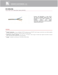
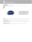
Kramer Electronics, Ltd. Preliminary USER MANUAL Models: TP-953, DVI/Audio Line Transmitter TP-954, DVI/Audio Line Receiver Contents Contents 1 2 2.1 3 3.1 4 4.1 4.2 5 5.1 5.2 6 Introduction Getting Started Quick Start Overview Using Twisted Pair Cable Your DVI/Audio Line Transmitter and Line Receiver Your TP-953 DVI/Audio Line Transmitter Your TP-954 DVI/Audio Line Receiver Connecting a DVI/Audio Transmitter/Receiver System Adjusting the EQ. Level Wiring the CAT 5 LINE IN/LINE OUT RJ-45 Connectors Technical Specifications 1 1 2 3 4 4 5 6 7 8 9 10 Figures Figure 1: TP-953 DVI/Audio Line Transmitter Figure 2: TP-954 DVI/Audio Line Receiver Figure 3: Connecting the TP-953/TP-954 Figure 4: CAT 5 Pinout 5 6 8 9 Tables Table 1: Features and Functions of the TP-953 Table 2: Features and Functions of the TP-954 Table 3: Equalization Level Setup Table 4: CAT 5 Pinout Table 5: TP-953/TP-954 Technical Specifications 5 6 8 9 10 i Introduction 1 Introduction Welcome to Kramer Electronics! Since 1981, Kramer Electronics has been providing a world of unique, creative, and affordable solutions to the vast range of problems that confront the video, audio, presentation, and broadcasting professional on a daily basis. In recent years, we have redesigned and upgraded most of our line, making the best even better! Our 1,000-plus different models now appear in 11 groups 1 that are clearly defined by function. Thank you for purchasing the Kramer MultiTOOLS™ TP-953 DVI/Audio Line Transmitter, TP-954 DVI/Audio Line Receiver, which is ideal for: • Home theater, presentation and multimedia applications • Rental and staging Each package includes the following items: • The TP-953 DVI/Audio Line Transmitter and/or TP-954 DVI/Audio Line Receiver • Power adapter (12V DC input) • This user manual 2 2 Getting Started We recommend that you: • Unpack the equipment carefully and save the original box and packaging materials for possible future shipment • Review the contents of this user manual • Use Kramer high-performance high-resolution cables 3 1 GROUP 1: Distribution Amplifiers; GROUP 2: Switchers and Matrix Switchers; GROUP 3: Control Systems; GROUP 4: Format/Standards Converters; GROUP 5: Range Extenders and Repeaters; GROUP 6: Specialty AV Products; GROUP 7: Scan Converters and Scalers; GROUP 8: Cables and Connectors; GROUP 9: Room Connectivity; GROUP 10: Accessories and Rack Adapters; GROUP 11: Sierra Products 2 Download up-to-date Kramer user manuals from our Web site at http://www.kramerelectronics.com 3 The complete list of Kramer cables is on our Web site at http://www.kramerelectronics.com 1 Getting Started 2.1 Quick Start This quick start chart summarizes the basic setup and operation steps. 2 KRAMER: SIMPLE CREATIVE TECHNOLOGY Overview 3 Overview Using the TP-953 DVI/Audio Line Transmitter with the TP-954 DVI/Audio Line Receiver constitutes a DVI/audio line transmitter/receiver system. The TP-953 accepts analog, S/PDIF, and optical audio and DVI video input signals, encodes and sends them over two CAT 5 cables. The TP-954 receives the CAT 5 signal, which includes both audio and video, decodes and distributes it to the audio and video acceptors. The TP-953 DVI/Audio Line Transmitter includes: • A DVI input • Three audio inputs: analog stereo, S/PDIF digital stereo, and optical • Two CAT 5 LINE OUT RJ-45 connectors for signal transmission to the TP-954 • Indicator LEDS for IN, OUT and power ON The TP-954 DVI/Audio Line Receiver includes: • Two CAT 5 LINE IN RJ-45 connectors for receiving signals from the TP-953 • A DVI output • Three audio outputs: analog stereo, S/PDIF digital stereo, and optical • Indicator LEDS for IN, OUT and power ON • An equalization select button In addition, the TP-953/ TP-954 system features: • System Range1—Up to 60m (197ft) at XGA, or up to 30m (98ft) at WUXGA on shielded BC-DGKat524 cable; 60m (197ft) at SXGA on shielded BC-DGKat623 cable; 60m (197ft) at SXGA on shielded BC-DGKat7a23 cable • Cables—For optimum range and performance, use Kramer's BC-DGKat524, BC-DGKat623 and BC-DGKat7a23 • Resolution up to WUXGA (reduced blanking) • HDCP compliance 1 Note that the transmission range depends on the signal resolution, graphics card and display used. The distance using nonKramer CAT 5, CAT 6 and CAT 7a cables may not reach these ranges 3 Your DVI/Audio Line Transmitter and Line Receiver To achieve the best performance: • Use only good quality connection cables 1 to avoid interference, deterioration in signal quality due to poor matching, and elevated noise levels (often associated with low quality cables) • Avoid interference from neighboring electrical appliances that may adversely influence signal quality and position your Kramer TP-953, TP-954 away from moisture, excessive sunlight and dust 3.1 Using Twisted Pair Cable Kramer engineers have developed special twisted pair cables to best match our digital twisted pair products; the Kramer BC-DGKat524 (CAT 5 24 AWG), the Kramer BC-DGKat623 (CAT 6 23 AWG cable), and the Kramer BC-DGKat7a23 (CAT 7a 23 AWG cable). These specially built cables significantly outperform regular CAT 5/CAT 6/CAT 7a cables. 4 Your DVI/Audio Line Transmitter and Line Receiver This section describes the: • TP-953 DVI/Audio Line Transmitter, see Section 4.1 • TP-954 DVI/Audio Line Receiver, see Section 4.2 1 Available from Kramer Electronics on our Web site at http://www.kramerelectronics.com 4 KRAMER: SIMPLE CREATIVE TECHNOLOGY Your DVI/Audio Line Transmitter and Line Receiver 4.1 Your TP-953 DVI/Audio Line Transmitter Figure 1 and Table 1 define the TP-953 unit. Figure 1: TP-953 DVI/Audio Line Transmitter # 1 Feature DVI IN Connector Function Connects to the DVI source (digital signals only) 2 ANALOG 3.5mm Mini Connector Connects to the analog audio source S/PDIF RCA Connector Connects to the digital audio source 4 AUDIO IN Table 1: Features and Functions of the TP-953 5 OUT A, OUT B RJ-45 Connectors Connects to the IN A, IN B connectors on the TP-954 1 6 12V DC +12V DC connector for powering the unit 7 IN LED Lights when an input source is connected 8 OUT LED Lights when an output acceptor is connected 9 ON LED Lights when receiving power 3 OPTICAL Connector Connects to the optical audio source 1 Using a straight pin to pin UTP cable with RJ-45 connectors at both ends (the pinout is defined in Table 4 and Figure 4) 5 Your DVI/Audio Line Transmitter and Line Receiver 4.2 Your TP-954 DVI/Audio Line Receiver Figure 2 and Table 2 define the TP-954 unit. Figure 2: TP-954 DVI/Audio Line Receiver Table 2: Features and Functions of the TP-954 # Feature Function IN A, IN B RJ-45 Connectors Connects to the OUT A, OUT B connectors on the TP-953 1 2 DVI OUT Connects to the DVI acceptor (digital signals only) 3 4 5 AUDIO OUT 1 ANALOG 3.5mm Mini Connector Connects to the analog audio acceptor S/PDIF RCA Connector Connects to the digital audio acceptor OPTICAL Connector Connects to the optical audio acceptor 6 12V DC +12V DC connector for powering the unit 7 EQ. SELECT Button Press to select equalization for the cable length 8 IN LED Lights when an input source is connected 9 OUT LED Lights when an output acceptor is connected 10 ON LED Lights when receiving power 1 Using a straight pin to pin UTP cable with RJ-45 connectors at both ends (the pinout is defined in Table 4 and Figure 4) 6 KRAMER: SIMPLE CREATIVE TECHNOLOGY Connecting a DVI/Audio Transmitter/Receiver System 5 Connecting a DVI/Audio Transmitter/Receiver System To connect a TP-953/TP-954 DVI/audio transmitter/receiver system (for example, a high-quality home cinema system), as Figure 3 illustrates, do the following: 1. On the TP-953 connect: A DVI video source 1 to the DVI IN connector and an audio source (for example, a computer graphics source) The two CAT 5 cables to OUT A and OUT B on RJ-45 connectors1 2. On the TP-954 connect: The OUT A CAT 5 cable from the TP-953 to the IN A RJ-45 connector on the TP-9541 The OUT B CAT 5 cable from the TP-953 to the IN B RJ-45 connector on the TP-9541 A DVI video acceptor1 (for example, a projector) to the DVI OUT connector An audio acceptor (for example, an AV receiver) 3. Connect the 12V DC power adapter to the power socket and connect the adapter to the mains electricity of either the TP-953 or the TP-9542. 4. Adjust the equalization level (see Section 5.1). 1 Do not connect an analog signal 2 If one of the devices does not power on, connect a power supply to both units 7 Connecting a DVI/Audio Transmitter/Receiver System Figure 3: Connecting the TP-953/TP-954 5.1 Adjusting the EQ. Level To adjust the equalization to compensate for various cable lengths: 1. Press the EQ. SELECT button for about 3 seconds to enter the setup mode. The IN or OUT LEDs flash according to their current setup. 2. Press and hold the EQ. SELECT button to cycle through the four equalization states, as defined in Table 3. Table 3: Equalization Level Setup LED STATUS IN LED OUT LED Flashing Off Flashing On Off Flashing On Flashing 8 Equalization Level Suitable for: Short cable length Medium cable length Long cable length Extra-long cable length KRAMER: SIMPLE CREATIVE TECHNOLOGY Connecting a DVI/Audio Transmitter/Receiver System 5.2 Wiring the CAT 5 LINE IN/LINE OUT RJ-45 Connectors Table 4 and Figure 4 define the STP CAT 5 pinout using a straight pin to pin cable with RJ-45 connectors. Note: The cable Ground shielding must be connected/soldered to the connector shield: Table 4: CAT 5 Pinout 1 2 3 4 5 6 7 8 EIA /TIA 568A PIN Wire Color Green / White Green Orange / White Blue Blue / White Orange Brown / White Brown 1 2 3 4 5 6 7 8 Figure 4: CAT 5 Pinout EIA /TIA 568B PIN Wire Color Orange / White Orange Green / White Blue Blue / White Green Brown / White Brown Pair 1 4 and 5 Pair 1 4 and 5 Pair 2 3 and 6 Pair 2 1 and 2 Pair 3 1 and 2 Pair 3 3 and 6 Pair 4 7 and 8 Pair 4 7 and 8 9 Technical Specifications 6 Technical Specifications The TP-953/TP-954 technical specifications are shown in Table 5. Table 5: TP-953/TP-954 Technical Specifications 1 TP-953 TP-954 INPUTS: 1 DVI 2 on a 24-pin Molex connector, 1 analog audio on a 3.5mm mini jack, 1 S/PDIF on an RCA connector, 1 optical on a TOSLINK® connector 2 CAT 5 IN on RJ-45 connectors OUTPUTS: 2 CAT 5 OUT on RJ-45 connectors 1 DVI2 on a 24-pin Molex connector, 1 analog audio on a 3.5mm mini jack, 1 S/PDIF on a RCA connector, 1 optical on a TOSLINK® connector MAX DATA RATE: CONTROLS: Supports up to 1.65Gbps per graphic channel N/A EQ. select pushbutton INDICATORS: IN, OUT, ON LEDs (green) POWER SOURCE: 12V DC, 460mA DIMENSIONS WEIGHT: 10.7cm x 10.4cm x 4.4cm (4.2" x 4.1" x 1.7") W, D, H 0.33kg (0.73lbs) ACCESSORIES: OPTIONS: Power supply 12V DC, 380mA 19” rack mount adapter, Kramer BC-DGKat524 (CAT 5 24 AWG), BC-DGKat623 (CAT 6 23 AWG) and BC-DGKat7a23 (CAT 7a 23 AWG) cables 3 1 Specifications are subject to change without notice 2 On a DVI-I connector. Note that only the digital signal (DVI-D) is available on the DVI connector 3 The complete list of Kramer cables is on our Web site at http://www.kramerelectronics.com 10 KRAMER: SIMPLE CREATIVE TECHNOLOGY LIMITED WARRANTY Kramer Electronics (hereafter Kramer) warrants this product free from defects in material and workmanship under the following terms. HOW LONG IS THE WARRANTY Labor and parts are warranted for three years from the date of the first customer purchase. WHO IS PROTECTED? Only the first purchase customer may enforce this warranty. WHAT IS COVERED AND WHAT IS NOT COVERED Except as below, this warranty covers all defects in material or workmanship in this product. The following are not covered by the warranty: 1. Any product which is not distributed by Kramer, or which is not purchased from an authorized Kramer dealer. If you are uncertain as to whether a dealer is authorized, please contact Kramer at one of the agents listed in the Web site www.kramerelectronics.com. 2. Any product, on which the serial number has been defaced, modified or removed, or on which the WARRANTY VOID IF TAMPERED sticker has been torn, reattached, removed or otherwise interfered with. 3. Damage, deterioration or malfunction resulting from: i) Accident, misuse, abuse, neglect, fire, water, lightning or other acts of nature ii) Product modification, or failure to follow instructions supplied with the product iii) Repair or attempted repair by anyone not authorized by Kramer iv) Any shipment of the product (claims must be presented to the carrier) v) Removal or installation of the product vi) Any other cause, which does not relate to a product defect vii) Cartons, equipment enclosures, cables or accessories used in conjunction with the product WHAT WE WILL PAY FOR AND WHAT WE WILL NOT PAY FOR We will pay labor and material expenses for covered items. We will not pay for the following: 1. Removal or installations charges. 2. Costs of initial technical adjustments (set-up), including adjustment of user controls or programming. These costs are the responsibility of the Kramer dealer from whom the product was purchased. 3. Shipping charges. HOW YOU CAN GET WARRANTY SERVICE 1. To obtain service on you product, you must take or ship it prepaid to any authorized Kramer service center. 2. Whenever warranty service is required, the original dated invoice (or a copy) must be presented as proof of warranty coverage, and should be included in any shipment of the product. Please also include in any mailing a contact name, company, address, and a description of the problem(s). 3. For the name of the nearest Kramer authorized service center, consult your authorized dealer. LIMITATION OF IMPLIED WARRANTIES All implied warranties, including warranties of merchantability and fitness for a particular purpose, are limited in duration to the length of this warranty. EXCLUSION OF DAMAGES The liability of Kramer for any effective products is limited to the repair or replacement of the product at our option. Kramer shall not be liable for: 1. Damage to other property caused by defects in this product, damages based upon inconvenience, loss of use of the product, loss of time, commercial loss; or: 2. Any other damages, whether incidental, consequential or otherwise. Some countries may not allow limitations on how long an implied warranty lasts and/or do not allow the exclusion or limitation of incidental or consequential damages, so the above limitations and exclusions may not apply to you. This warranty gives you specific legal rights, and you may also have other rights, which vary from place to place. NOTE: All products returned to Kramer for service must have prior approval. This may be obtained from your dealer. This equipment has been tested to determine compliance with the requirements of: EN-50081: EN-50082: CFR-47: "Electromagnetic compatibility (EMC); generic emission standard. Part 1: Residential, commercial and light industry" "Electromagnetic compatibility (EMC) generic immunity standard. Part 1: Residential, commercial and light industry environment". FCC* Rules and Regulations: Part 15: “Radio frequency devices Subpart B Unintentional radiators” CAUTION! Servicing the machines can only be done by an authorized Kramer technician. Any user who makes changes or modifications to the unit without the expressed approval of the manufacturer will void user authority to operate the equipment. Use the supplied DC power supply to feed power to the machine. Please use recommended interconnection cables to connect the machine to other components. * FCC and CE approved using STP cable (for twisted pair products) 11 For the latest information on our products and a list of Kramer distributors visit www.kramerelectronics.com where updates to this user manual may be found. We welcome your questions, comments and feedback. Safety Warning: Disconnect the unit from the power supply before opening/servicing. Caution Kramer Electronics, Ltd. Web site: www.kramerelectronics.com E-mail: [email protected] P/N: 2900-000516 REV 5