1
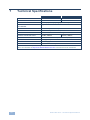
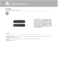
K R A ME R E LE CT R O N IC S L TD . USER MANUAL MODELS: PT-571 HDMI Line Transmitter PT-572+ HDMI Line Receiver P/N: 2900-000690 Rev 8 Contents 1 Introduction 1 2 2.1 2.2 2.3 3 3.1 3.2 Getting Started Achieving the Best Performance Safety Instructions Recycling Kramer Products Overview Using Twisted Pair Cable About the Power Connect™ Feature 2 2 2 3 4 5 5 4 Defining the PT-571 HDMI Line Transmitter 6 5 Defining the PT-572+ HDMI Line Receiver 7 6 6.1 Connecting the PT-571 and PT-572+ Transmitter Receiver Pair Wiring the TP Line In/Line Out RJ-45 Connectors 8 9 7 Technical Specifications 10 Figures Figure 1: PT-571 HDMI Line Transmitter Figure 2: PT-572+ HDMI Line Receiver Figure 3: Connecting the PT-571/PT-572+ Transmitter/Receiver Pair Figure 4: TP Pinout Wiring PT-571/PT-572+ – Contents 6 7 8 9 i 1 Introduction Welcome to Kramer Electronics! Since 1981, Kramer Electronics has been providing a world of unique, creative, and affordable solutions to the vast range of problems that confront video, audio, presentation, and broadcasting professionals on a daily basis. In recent years, we have redesigned and upgraded most of our line, making the best even better! Our 1,000-plus different models now appear in 11 groups that are clearly defined by function: GROUP 1: Distribution Amplifiers; GROUP 2: Switchers and Routers; GROUP 3: Control Systems; GROUP 4: Format/Standards Converters; GROUP 5: Range Extenders and Repeaters; GROUP 6: Specialty AV Products; GROUP 7: Scan Converters and Scalers; GROUP 8: Cables and Connectors; GROUP 9: Room Connectivity; GROUP 10: Accessories and Rack Adapters and GROUP 11: Sierra Video Products. Congratulations on purchasing your Kramer PT-571 and PT-572+ transmitter/receiver pair, which is ideal for the following typical applications: Boardrooms, conference rooms and training rooms Presentation systems Signal distribution and home theater ! ! You must use Shielded Twisted Pair (STP) cabling with the PT-571 and PT-572+. Use only a straight pin-to-pin cable with RJ-45 connectors that meet the EIA /TIA 568B standard. Failure to do so may result in damage to the device(s). PT-571/PT-572+ - Introduction 1 2 Getting Started We recommend that you: Unpack the equipment carefully and save the original box and packaging materials for possible future shipment Review the contents of this user manual i 2.1 Go to http://www.kramerelectronics.com/support/product_downloads.asp to check for up-to-date user manuals, application programs, and to check if firmware upgrades are available (where appropriate). Achieving the Best Performance To achieve the best performance: Use only good quality connection cables (we recommend Kramer highperformance, high-resolution cables) to avoid interference, deterioration in signal quality due to poor matching, and elevated noise levels (often associated with low quality cables) Do not secure the cables in tight bundles or roll the slack into tight coils Avoid interference from neighboring electrical appliances that may adversely influence signal quality Position your Kramer PT-571 away from moisture, excessive sunlight and dust ! 2.2 Safety Instructions ! 2 This equipment is to be used only inside a building. It may only be connected to other equipment that is installed inside a building. Caution: There are no operator serviceable parts inside the unit Warning: Use only the Kramer Electronics input power wall adapter that is provided with the unit Warning: Disconnect the power and unplug the unit from the wall before installing PT-571/PT-572+ - Getting Started 2.3 Recycling Kramer Products The Waste Electrical and Electronic Equipment (WEEE) Directive 2002/96/EC aims to reduce the amount of WEEE sent for disposal to landfill or incineration by requiring it to be collected and recycled. To comply with the WEEE Directive, Kramer Electronics has made arrangements with the European Advanced Recycling Network (EARN) and will cover any costs of treatment, recycling and recovery of waste Kramer Electronics branded equipment on arrival at the EARN facility. For details of Kramer’s recycling arrangements in your particular country go to our recycling pages at http://www.kramerelectronics.com/support/recycling/. PT-571/PT-572+ - Getting Started 3 3 Overview The PT-571 is a DGKat™ twisted pair transmitter for HDMI signals. The PT-571 converts an HDMI signal to a single twisted pair signal and the PT-572+ converts the twisted pair signal back to an HDMI signal. The HDMI Line Transmitter/Receiver system features: Maximum data rate 4.95Gbps (1.65Gbps per graphic channel) HDTV compatibility HDCP compliance HDMI support EDID PassThru that passes EDID signals between the source and display 3D pass-through System Range – Up to 90m (295ft) at 1080i, or up to 30m (98ft) at 1080p on shielded BC-DGKat524 cable; 90m (295ft) at 1080i, or up to 70m (230ft) at 1080p on shielded BC-DGKat623 cable; 100m (330ft) at 1080i or up to 90m (295ft) at 1080p on shielded BC-DGKat7a23 cable Note that the transmission range depends on the signal resolution, graphics card and display used. The distance using non-Kramer CAT 5, CAT 6 and CAT 7a cables may not reach these ranges DGKat™ Signal Integration – Kramer’s unique technology for converting TMDS as well as control and communication to signals that run over twisted pair cables Power Connect™ that feeds 12V DC over the CAT 5 cable from transmitter to receiver (see Section 3.2) Ultra-Compact PicoTOOLS™ – 4 units can be rack mounted side−by−side in a 1U rack space with the optional RK−4PT rack adapter. i 4 Use only shielded cable where both ends of the shield are soldered to ground to eliminate ESD interface. PT-571/PT-572+ - Overview 3.1 Using Twisted Pair Cable Kramer engineers have developed special twisted pair cables to best match our digital twisted pair products; the Kramer: BC-DGKat524 (CAT 5 24 AWG), the Kramer: BC-DGKat623 (CAT 6 23 AWG cable), and the Kramer: BC-DGKat7a23 (CAT 7a 23 AWG cable). These specially built cables significantly outperform regular CAT 5/CAT 6/CAT 7a cables. 3.2 About the Power Connect™ Feature The Power Connect™ feature here means that only one unit in a system, the transmitter or receiver, needs to be connected to a power source when the devices are within 60m (197ft) of each other. The Power Connect™ feature applies as long as the cable can carry power and the distance does not exceed 60m on standard TP cable. (Heavier gauge cable may be used to extend the Power Connect™ range). PT-571/PT-572+ - Overview 5 4 Defining the PT-571 HDMI Line Transmitter The Kramer PicoTOOLS PT-571 HDMI Line Transmitter receives an HDMI signal, encodes it, and transmits it over a CAT 5 cable to the PT-572+. The PT-571 has: An HDMI input connector An RJ-45 CAT 5 output connector One power/status LED Figure 1: PT-571 HDMI Line Transmitter # 1 12V DC Feature Function +12V DC connector for powering the unit 2 HDMI IN Connector Connect to the HDMI source 3 ON LED Lights to indicate the following: Red—only the power is connected Orange—either the input or the output is connected Green—both the input and the output are connected If no input is connected the unit invokes the power save mode automatically turning off the power 4 6 OUT RJ-45 Connector Connect to the IN RJ-45 connector on the PT-572+ PT-571/PT-572+ - Defining the PT-571 HDMI Line Transmitter 5 Defining the PT-572+ HDMI Line Receiver The Kramer Pico TOOLS PT-572+ HDMI Line Receiver receives an encoded signal over a CAT 5 cable transmitted from the PT-571, decodes it, and converts it to an HDMI output. The PT-572+ has: An HDMI output connector An RJ-45 CAT 5 input connector One power/status LED Figure 2: PT-572+ HDMI Line Receiver # 1 12V DC Feature Function +12V DC connector for powering the unit 2 HDMI OUT Connector Connect to the HDMI acceptor 3 ON LED Lights to indicate the following: Red—only the power is connected Orange—either the input or the output is connected Green—both the input and the output are connected 4 IN RJ-45 Connector Connect to the OUT RJ-45 connector on the PT-571 PT-571/PT-572+ - Defining the PT-572+ HDMI Line Receiver 7 6 Connecting the PT-571 and PT-572+ Transmitter Receiver Pair ! Always switch off the power to each device before connecting it to your PT-571/PT-572+. After connecting your PT-571/PT-572+, connect the power and then switch on the power to each device. You can use the PT-571 HDMI Line Transmitter with the PT-572+ HDMI Line Receiver to configure an HDMI transmitter/receiver system. Figure 3: Connecting the PT-571/PT-572+ Transmitter/Receiver Pair To connect the PT-571 to the PT-572+, as illustrated in the example in Figure 3, do the following: 1. Connect the CAT 5 OUT RJ-45 connector on the PT-571 to the CAT 5 IN RJ-45 connector on the PT-572+ via a CAT 5 cable (see Section 6.1). 2. On the PT-571, connect an HDMI source (for example, a DVD player) to the HDMI IN connector. 3. On the PT-572+, connect the HDMI OUT connector to an HDMI acceptor (for example, a plasma display). 8 PT-571/PT-572+ - Connecting the PT-571 and PT-572+ Transmitter Receiver Pair 4. Connect the 12V DC power adapter to the power socket on the PT-571 and/or the PT-572+ and connect the adapter to the mains electricity (not shown in Figure 3). Note: When connecting the PT-572+ to the VP-81SID do not connect the 12V power supply to the PT-572+. 6.1 Wiring the TP Line In/Line Out RJ-45 Connectors This section defines the TP pinout, using a straight pin-to-pin cable with RJ-45 connectors. i Note, that the cable Ground shielding must be connected / soldered to the connector shield. EIA /TIA 568B PIN 1 Wire Color Orange / White 2 Orange 3 Green / White 4 Blue 5 Blue / White 6 Green 7 Brown / White 8 Brown Pair 1 4 and 5 Pair 2 1 and 2 Pair 3 3 and 6 Pair 4 7 and 8 Figure 4: TP Pinout Wiring PT-571/PT-572+ - Connecting the PT-571 and PT-572+ Transmitter Receiver Pair 9 7 Technical Specifications PT-571 PT-572+ INPUTS: 1 HDMI connector 1 RJ-45 connector OUTPUTS: 1 RJ-45 connector 1 HDMI connector BANDWIDTH: 4.95Gbps (1.65Gbps per graphic channel) COMPLIANCE WITH HDMI STANDARD: Supports HDMI and HDCP OPERATING TEMPERATURE: 0° to +40°C (32° to 104°F) STORAGE TEMPERATURE: HUMIDITY: -40° to +70°C (-40° to 158°F) 10% to 90%, RHL non-condensing POWER CONSUMPTION: 12V DC, 250mA DIMENSIONS: 6.2cm x 5.2cm x 2.4cm (2.4" x 2.1" x 1") W, D, H WEIGHT: 0.14kg (0.3lbs) ACCESSORIES: Power supply OPTIONS: RK-4PT 19” rack adapter 12V DC, 250mA Specifications are subject to change without notice Go to our Web site at http://www.kramerelectronics.com to access the list of resolutions 10 PT-571/PT-572+ - Technical Specifications For the latest information on our products and a list of Kramer distributors, visit our Web site where updates to this user manual may be found. We welcome your questions, comments, and feedback. Web site: www.kramerelectronics.com E-mail: [email protected] ! SAFETY WARNING Disconnect the unit from the power supply before opening and servicing P/N: 2900- 000690 Rev: 8