1
Installation Manual for UK and Ireland
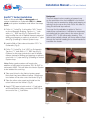
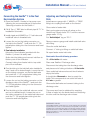
7 Install 1/2” ball valve onto venturi (Fig 7).
8 Close the valve (Fig 8).
9 Note the arrow on the venturi indicating the
direction of flow (Fig 9). If there is no arrow
Fig 7
marked on your Venturi, the direction of flow
must go from the shorter end to the longer end.
Fig 8
Fig 9
10
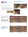
Complete installation of venturi
bypass loop using 11/2” PVC
pipe and fittings. There are four
methods profiled in the following
figures.
Drill & Tap
Note: When performing step 10,
make sure the venturi is installed
with correct direction of flow.
Above Grade
Below Grade
Tees
Refer to glue manufacturers
recommendations regarding
drying times, before re-starting
the pool pump.
Above Grade
Below Grade
9