1
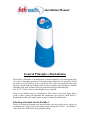
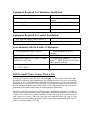
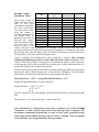
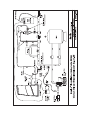
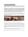
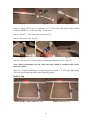
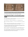
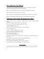
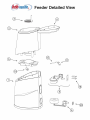
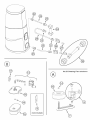
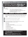
Installation Manual for UK and Ireland Model 75876 Arch Chemicals Ltd Wheldon Road Castleford WF10 2JT 01977 714100 9/16/03 REV 1 Product Stewardship MAKING THE WORLD A BETTER PLACE Arch is committed to maintaining and improving our leadership in Product Stewardship. One of the six initiatives outlined under the Chemical Manufacturers Association (CMA) Responsible Care® Program is to make health, safety, and environmental protection an integral part of a product’s life cycle – from manufacture, marketing, and distribution to use, recycling, and disposal. Successful implementation is therefore, a shared responsibility. Everyone involved with the product has responsibilities to address society’s interest in a healthy environment and in products that can be used safely. We are each responsible for providing a safe workplace. All who use and handle products must follow safe and environmentally sound practices. For more information about our Product Stewardship Program, contact your Arch Representative. Installation Manual General Principles of Installation The Easiflo 1 chlorinator is an atmospheric system designed for pools and ranging from 15 to 600 m3 depending on bather load and operating conditions. It is possible to install the feeder on a pool and dose a spa or small pool also with a conventional dosing pump drawing solution from the discharge tank, but this possibility again depends on volumes and bather load. Arch Technical Services personnel can help to determine this. Tel:- 01977 714100 for this or other helpful advice if needed. There are two different types of installations. The location of the pool pump (above grade or below grade) will determine the installation type necessary. Both Easiflo 1 installations use the small feeder venturi to inject chlorine post filter/heater. Selecting a location for the Easiflo 1: Choose a location in the pump room that will allow easy access and service. Always try to minimize the length of the outlet tubing when locating the Easiflo 1. The Easiflo 1 comes with 6mt of half inch OD polyethylene tubing. Equipment Required for Chlorinator Installation: Drill - Cordless Recommended PTFE or Pipe Sealant /2” MBSP x 1/4” FBSP Reducing Bushing PVC Primer/Cleaner and PVC Glue Saw to cut PVC Pipe Gas Pliers (Channel Locks) 1 /2” BSP Tap and 11/16” Drill Bit Tube Cutters or Utility Knife 1 Vacuum Gauge (Inches of Hg) Equipment Required for Venturi Installation: 1” PVC Pipe and Fittings (elbows, tees etc.) Ball or Gate Valve for Pool Return Line 11/2” BSP Tap and 13/4” Hole Saw (Optional) Saddle Clamps (optional) Parts Included with the Easiflo 1 Chlorinator: 1 /2” OD Polyethylene Tubing (20 feet) (2) 1/2” FBSP x FBSP PVC ball valve/W8MC8 Parker tubing connector: 1” Tube x 1” MBSP (W8MC4) for ESV inlet Arch Venturi (2) 1/2” PVC Nipples /2” FBSP threaded Sch. 40 PVC coupling 0 - 4lts acrylic flow indicator 1 (3) Parker tubing connector: 1/2” OD tube x 1/2” FBSP (W8FC8) for discharge valve and flow indicator (2) 11/2” Slip x Slip Sch. 40 PVC Unions Will the Small Feeder Venturi Work @ Site Ask the pool operator what the flow rate (minimum) of the pool is with a dirty filter. Backwash or clean the filter and measure the effluent pressure of the pool system after the heater at “P1” in the Installation Schematic. If this pressure is 17psi or less and the minimum flow rate of the pool is greater than 170 lts /min, the small feeder venturi will provide adequate suction to operate the Easiflo 1. The chart overleaf lists the suction flow generated by the small feeder venturi at various pressure differentials. Install the venturi loop as shown in the appropriate Installation Schematic for either an above or below grade filtration system. The primary difference between the two is the use of ball valves on the below grade installation to allow the loop to be isolated from the pool system for service. Once the loop has been installed using the step by step instructions in the Installation Manual, adjust the pressure differential ball valve to achieve a vacuum reading of 13” Hg. Easiflo 1 Venturi Installation: Theory Inlet Pressure (psi) 5.5 Outlet Pressure (psi) 5 5 6 6 7 7 10 10 12 15 15 17 17 Flow Through Suction Flow Venturi (lts /min) (lts /min) 87 3.78 106 6.00 91 3.78 106 1.5 98 3.78 106 4.92 121 3.78 128 4.92 140 3.78 144 3.78 148 4.92 155 3.78 159 4.92 Flow to the venturi is 6 taken from the pressure 6.5 side of the pool 7.5 recirculation pump after 7.5 the filter and heater 8 loop (if present). Flow 12 from the venturi is 12.5 returned downstream of 15.5 the venturi inlet. A partially closed valve in 17.5 between the venturi 18 inlet and outlet provides 21.5 the pressure drop 22 needed to power the venturi. The three critical parameters in choosing a venturi are the inlet and outlet pressures and the suction lift. The Venturi must be capable of evacuating 4lt /min from the discharge tank when the filter is dirty. Suction flow will decrease with an increase in filter pressure as less water will flow through venturi. Always minimize the backpressure when installing a venturi. This includes eliminating/minimizing any elbows on the outlet side of the venturi. In addition, if the venturi is located more than 0.9 metres above the chlorinator outlet, it will be necessary to calculate the effect of the suction lift loss on outlet flow. Follow instructions below to perform the Suction Lift calculation if required. After the evacuation system has been laid out, measure the height differential (in metres) between the venturi and discharge valve of the Easiflo®1 chlorinator. Use this height differential to calculate the suction lift factor in the formula that follows. Suction lift factor = (10.37 – height differential in metres) / 10.37 Example: height differential is 2 metres, therefore Suction lift factor = (10.37 - 2) / 10.37 = 8.37 / 10.37 = 0.81 Take the suction flow (F1) and multiply it by the suction lift factor to get the actual outlet flow. The formula is: F1 x suction lift factor = actual outlet flow After installation, it is important to check the evacuation cycle of the Easiflo1 Chlorinator to ensure that the drain time of the discharge tank is adequate. The maximum recommended elapsed time to drain a 4 litre bottle (positioned at the same height of the Easiflo1 discharge valve) of water is 1 minute. This corresponds to an outlet flow-rate of approximately 4 litres per minute. Venturi System Installation: Refer to schematic #2AG for either above grade pool system / auto control installation or Schematic #2BG for a below grade pool system installation and follow the steps below. Background: The next steps involve creating a bypass loop on the pool return line for installation of a Venturi. This loop can be created by drilling and tapping or splicing into the return line with Tee’s. We refer to using the drill and tap method. You may find it preferable to splice in Tee’s to make these connections. It will also be necessary to install a ball (or gate) valve in the return line at location “PD1” in the schematic drawing. This valve when partially closed, will force water to flow through the venturi creating the suction needed to evacuate the chlorinator. Step #1: Drill a 13/4” hole (Fig 1V) at location “VS1” found on the schematic drawing. Tap the 13/4” hole with a 11/2” BSP tap (Fig 2V). Options for this step include the use of saddle clamps instead of drilling and tapping or splice in a tee with 1” pipe size (Fig 3V) leading to Venturi System loop. Fig 1V Fig 2V Fig 3V Step #2: Install a Ball or Gate valve at location “PD1” in Schematic (Fig 4V). Step #3: Drill a 13/4” hole (Fig 10) at “VS2” on Schematic. Tap the 13/4” hole with a 11/2” BSP tap (Fig 2V). Options for this step include the use of saddle clamps instead of drilling and tapping or splice in a tee with 11/2” pipe size (Fig 3V) leading to Venturi System loop. Note: Below grade systems will require the addition of ball valves at locations “BV1 & BV2” in schematic #2BG. This will allow the Venturi System to be isolated for servicing. Step #4: Take one Union for the Venturi system apart. Note that they have different halves. Glue these two halves of the union onto the Venturi (Fig 5V). Step #5: Take the other union apart and install on the union halves on the Venturi. (Fig 6V). Fig 4V Fig 5V Fig 6V Step #6: Apply PTFE tape to both ends of 1/2” ball valve and install Parker tubing connector (W8FC8) on one end of the 1/2” ball valve. Step #7: Install 1/2” ball valve onto venturi (Fig 7V). Step #8: Close the valve (Fig 8V). Fig 7V Fig 8V Fig 9V Step #9: Note the Arrow on the venturi indicating the direction of flow (Fig 9V). Note: When performing step #10, make sure the venturi is installed with correct direction of flow. Step #10: Complete installation of venturi bypass loop using 11/2” PVC pipe and fittings. There are four methods profiled in the following figures. Drill & Tap Above Grade / Auto Control Fig 19A Below Grade Fig 19C 10 Tees Above Grade / Auto Control Fig 19B Below Grade Fig 19D Allow at least 30 minutes for glue to set before restarting the pool pump. Note: Perform the following procedure while the glue is drying. Connecting the Easiflo 1 to the Pool Recirculation System Step #1: Place the Easiflo 1 chlorinator in the pump room following the recommendations in the section ‘Selecting a location for the Easiflo 1’. Step #2: Drill & Tap 1/2” BSP hole in effluent pipe @ “P1” in Plumbing Schematic. Step #3: Install nipple and W8MC8 on 1/2” ball valve and install ball valve in threaded hole. Step #4: Loosen the nut on the Parker tubing connector on the inlet to the Easiflo 1 and push the 1/2” OD polyethylene tubing into the connector and hand tighten. Step #5: Run the tubing to the inlet ball valve installed in step 3 and cut to desired length. Loosen the nut on the Parker tubing connector on the inlet ball valve and push the 1/2” OD polyethylene tubing into the connector and hand tighten. Step #6: Loosen the nut on the Parker tubing connector on the discharge valve of the Easiflo 1 and push the 1/2” OD polyethylene tubing into the connector and hand tighten. Step #7: Run the tubing to the outlet ball valve on venturi and cut to desired length. Loosen the nut on the Parker tubing connector on the outlet ball valve and push the 1/2” OD polyethylene tubing into the connector and hand tighten. Flow Indicator Installation A flow indicator is provided with the Easiflo®1 and has a scale from 0 to 4 lt / min. Follow the instructions below to install a flow indicator. Step #1: Close the inlet and the outlet shutoff valves to the Easiflo®1 chlorinator. Step #2: Mount flow indicator where it is easily read. Step #3: Splice into inlet tubing and connect inlet flow to bottom port of flow indicator. Step #4: Connect tubing from chlorinator inlet to top outlet port of flow indicator. Adjusting and Testing the Outlet Flow Rate Install vacuum gauge with 1” MBSP x 1” FBSP fitting into coupling and install on the Venturi. Start pool system and open all valves on the venturi loop. Slowly close “PD1” until the vacuum gauge reads 13” Hg. Put “Do Not Adjust” tag on “PD1”. Remove vacuum gauge and install outlet ball valve with fitting. Close the outlet ball valve. Connect 1/2” tubing to fitting on outlet ball valve. Check outlet flow with following procedure. Fill a 4 litre bottle with water. Place near Easiflo®1 Discharge valve. Disconnect the tubing from the discharge valve and place end of tubing at bottom of 4 litre bottle. Open outlet ball valve and record time it takes to empty the bottle. It should take 1 minute or less to empty the bottle. This corresponds to an outlet flow rate of 4 lt / min or greater. Close outlet ball valve and connect tubing to the discharge valve. WARRANTY POLICY The Easiflo® Chlorine Feeder comes with a 12 month warranty from the date of installation. In order for the warranty to be validated the Warranty Registration Document W2 must be completed and returned to Arch Water Products, Wheldon Road, Castleford WF10 2JT. ISSUE 1 SPRING 2003 ARCH WATER PRODUCTS RESPONSIBLE CARE GUIDANCE NOTE AWP RC 2003/1 EMERGENCY RESPONSE PROCEDURE FOR ARCH WATER PRODUCTS CUSTOMERS 1 In the event of a Health Safety or Environmental Emergency involving Arch Water products. This includes • Injury to persons requiring medical treatment • Loss of containment of product to the environment • Involvement of the Emergency Services (Police, Fire, Medical) • Involvement of the Environmental agencies • Major damage to property FIRST TELEPHONE + 44 (0)1865 407333 This will connect you with the NCEC (National Chemical Emergency Centre) who support the Arch Emergency Response. (It operates 24 hours a day, 365 days a year). THEN Phone your local Arch Water Products Office (during office hours) 2 NCEC will provide initial assistance and advice (in English). 3 NCEC will also contact Arch Water Products Head Office. 4 When calling the Emergency No. have the following information available (use your Emergency Response Procedure Checklist): • Your name • Your job title • Your company name and location • The Telephone (and fax) number that you can be contacted on • The Product Name • The Product Code • The nature of the emergency • The action you have taken • Are the emergency services involved? • Are the environmental agencies involved? PLEASE ALWAYS CONTACT NCEC IN THE EVENT OF A HEALTH, SAFETY OR ENVIRONMENTAL EMERGENCY INVOLVING ARCH WATER PRODUCTS BUT PLEASE ONLY USE THIS NUMBER FOR HEALTH, SAFETY AND ENVIRONMENTAL EMERGENCIES (as defined above).