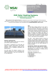
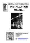
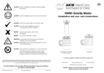
1
STC Solar Installation Guide Installation of Solar Tube Company Solar SPA Collector Kits Warning: Only install your system if you and any persons working with you are competent to do so, and only after you have assessed all risks, and either eliminated them or reduced them to safe levels. Caution: There is a boiling risk, which is fully avoidable. Either fit the tubes at the end of the installation after the system is filled or shade the tubes prior to commissioning. Installation G Realise the Benefits! Thank you for choosing a STC Solar Thermal System. We have prepared this guide to assist you with the installation of your new system, don’t forget we are here to help so please let us know if you are having problems or require some more clarification. Just in case you need reminding why you chose a STC System, here are the key features of our kits: 1. 2. 3. 4. 5. Fast payback Fast installation No leaks Reduced maintenance 25 + years life Contents 1. 2. 3. 4. 5. 6. 7. General Collector positioning Collector installation Pipe work installation Leaded roof grommets and 2-in-2 stainless pipe Filling the System Fitting the Tubes Solar Tube Company - Eco Airpump www.ecoairpump.co.uk Support Line: 08444 930099 2 Installation G General Installation of a solar thermal heating system usually requires safe working at heights on a roof. It is essential to check that the rafters are strong enough (rafters should have a minimum cross-sectional area of 75 sq cm); if in any doubt, ask a structural engineer to advise. Collector Positioning The optimum performance of the collector will be achieved when it is positioned at a 50 to 60 tilt angle in a south facing direction. A more vertical tilt angle will favour performance during the winter at the expense of reducing the maximum performance during the summer. Evacuated tube collectors using radial absorbers (such as the SPA models) will perform well even when not pointing due south. However, it will be necessary to increase the number of tubes over what would be expected for a due south installation: Position West South West South East East Allow % extra evacuated tubes 25% 10% 20% 35% An alternative is to fit collectors to more than one roof surface. For example, collectors can be fitted to east and west facing elevations in conjunction with an upgraded controller (such as the Resol BS Plus) switching the flow from the east to the west collector during the day via a motorised 3-way valve. For flat roofs, the use of a Flat Roof Mounting Frame is recommended. Collector Installation The collector is typically attached to the roof by stainless steel brackets or by stainless steel banding (some installers use other methods). The brackets are fixed directly to the rafters where possible, or to noggins fitted between rafters. Fitment to roof battens is not recommended. Solar Tube Company - Eco Airpump www.ecoairpump.co.uk Support Line: 08444 930099 3 Installation G Frame Assembly (for Pitched Roof Installations) (For 24/30 tube collectors use 3 vertical pieces) 1. Attach frame vertical pieces to back of manifold 2. Turn over 3. Attach cross rail so that opened groove is at top 4. 5. Secure cross rails using M13 bolts and stainless fittings The collector can now be offered up to the roof in order to find the best place to fix it. Use chalk or tape to mark the chosen position. The rafter spacing can usually be seen at the bottom of the roof covering (next to the gutter). Solar Tube Company - Eco Airpump www.ecoairpump.co.uk Support Line: 08444 930099 4 Installation G Flat Roof Frame Assembly (For 24/30 tube collectors use 3 legs / side supports) 1. 6. Attach legs to top of frame (M10 X 45 bolts) 2. Attach feet, folding in tabs to fit (M10 X 45 bolts) 3. Attach side supports (M13 x 20 bolts) 4. Attach rear supports (M13 x 20 bolts) 5. Join rear supports at middle of X (M10 x 30 bolt) The collector can now be offered up to the roof in order to find the best place to fix it. Use chalk or tape to mark the chosen position. The rafter spacing can usually be seen at the bottom of the roof covering (next to the gutter). Solar Tube Company - Eco Airpump www.ecoairpump.co.uk Support Line: 08444 930099 5 Installation G Stainless Steel Roof Bolts 1. Undo the nuts on the back of the manifold and assemble the frame (it shouldn't use washers), then offer this up to the roof and mark the top and bottom slots on the frame on to the tiles using chalk or a drill etc... Try to catch the rafter on one side - it makes it easier. 2. Drill 10-12mm holes using a bit without hammer. Go inside and make up noggins to line up with the holes that are not in line with the rafters (you will see the holes very clearly). 3. Back on the roof, drill pilot holes into the wood, drilling through your holes in the tiles using a 6-8mm bit. 4. Wind in the bolts using an adjustable spanner so that the frame sits level with the roof, clamped between the top pair of nuts/washers. The lower nut/washer tightens the EPDM washer to the roof tile. Please note that you have the new thicker roof bolts so you will need to widen the top and bottom slots in the frame using a file or a drill (not difficult, the frames are only 1.2mm stainless steel) in order to take the roof bolts without damaging the thread. Solar Tube Company - Eco Airpump www.ecoairpump.co.uk Support Line: 08444 930099 6 Installation G Connecting the Pipe Work to the Collector There are many ways in which to attach the pipe work to the collectors, different installers preferring different methods. The flow and return pipes are connected to the collector by means of 22mm compression couplings. These may be the type supplied with the flexible stainless pipe, standard 22mm brass fittings (between 2 collectors for example), right angle 22mm brass fittings or 22mm T brass fittings (if an external air vent is fitted). In all cases, a hole must be cut in the tiles at each end of the collector (or at each end of a multiple collector array). The 22mm copper pipe tails protruding from each end of the collector can be trimmed using a pipe cutter to give a closer fit. However, it is recommended that there remain a 5mm gap between the end of the collector and the fitting to allow for expansion/contraction. Using DN16 2-in-2 Pre-Insulated Stainless Steel Flexible Pipe The 2 pipes can be separated by cutting the insulation apart using a craft knife or similar: Cut around the insulation to reveal the pipe, this is then cut using a pipe cutter. Solar Tube Company - Eco Airpump www.ecoairpump.co.uk Support Line: 08444 930099 7 Installation G 1. Feed the stainless pipe through a back nut, threads facing cut end. 2. Tighten a securing clip around the last groove on the pipe (one raised segment protruding from clip). 3. The back nut is attached to the fitting WITHOUT the washer and tightened – this creates a flange on the end of the pipe. 4. Unscrew the fitting, insert the washer, reconnect the fitting and tighten. The compression fittings attach to the ends of the manifold. The PAW self seal nipples attach to the inlet and outlet of the pump station, black rubber seal ends connecting to pump station, bare thread ends connecting to back nut. Various additional fittings to connect to the back nuts are available. Solar Tube Company - Eco Airpump www.ecoairpump.co.uk Support Line: 08444 930099 8 Installation G Using Leaded Roof Grommets and Pre-Insulated Flexible Stainless Steel Pipe The size of the hole is less important when using leaded roof grommets because they provide their own weatherproof seal. They can be used instead of the tile beneath them. In which case, simply lay the leaded tile in the gap left by the replaced roof tile, making sure that the top edge lies under the tile immediately above it and the bottom edge lies on top of the tile immediately below it – to keep the rain out. Typically, holes of 60-80mm diameter are cut using a ceramic hole cutter, centres of the holes should be 100mm from the ends of the 22mm copper tails. The holes should be slightly below the tails in order to prevent air locks. If using a Flowcon S pump station; an exterior air vent is not usually necessary. The leaded roof grommet is then placed over the tile and trimmed to fit, ensuring that it lies under the lower edge of the tile immediately above it. The rubber grommets should be cut between the second and third ridge leaving a hole through which the pipe can be fed (including its insulation). Remove the black (high temperature) sensor provided with the controller from the pump station box, smear some heat transfer paste (from the tube in the small white box found in the collector frame box) onto the metal sensor tube and push into the sensor pocket. The sensor pocket will accept many types of sensor so try not to push the Resol sensor in too far – the whole sensor tube should be inside the manifold with the end just inside the rubber grommet. The sensor wire can now go through the small lump beside the main part of the lead roof grommet and be joined on to the blue sensor wire. NB. The fluid flows from the left of the collector to the right as viewed from the front. This is because the sensor pocket is on the right side of the collector i.e. the heat reading is taken as the water leaves the collector. It is recommended that the sensor wire be joined inside the roof void. Therefore, cut the insulation of the pipe containing the blue sensor cable about 1 metre before the cut end. Pull the blue sensor wire out. The DN16 2-in2 pipe is then fed from inside the roof void through the 2 holes. Use back nuts and compression fittings to connect to manifold. Stretch insulation over fittings. Connect the sensor wire to the blue cable then run the DN16 pipe down to the pump station, taking care to avoid any high points that could lead to air locks. The pipe is usually held in place using our brackets or thick cable ties. Solar Tube Company - Eco Airpump www.ecoairpump.co.uk Support Line: 08444 930099 9 Installation G The Pump Station This is usually located in beside the hot water cylinder. The control panel can be removed from the unit and located elsewhere to provide more convenient control/display (by extending the electrical cable running from the controller to the pump). Connect the return DN16 2-in-2 pipe (the one carrying fluid back to the collector) to the top connection of the pump station using a PAW self seal nipple and the back nut – black rubber seal facing towards the pump station. Connect the flow DN16 2-in-2 pipe (the one carrying the heated fluid from the collector) to the inlet (upper) of the water cylinder’s solar coil. Connect the outlet (lower) of the water cylinder’s solar coil to the bottom connection of the pump station using a PAW self seal nipple and the back nut – black rubber seal facing towards the pump station. The recommended flow rate for domestic hot water is 0.1 – 0.2 litres/minute per tube (i.e. 2 – 3 litres per minute for single 20 tube collector). The expansion vessel can be located beside the pump station or elsewhere by means of attaching a length of un-insulated copper pipe. For full fitting and commission, see instructions provided with pump station. Solar Tube Company - Eco Airpump www.ecoairpump.co.uk Support Line: 08444 930099 10 Installation G Filling the Resol Flowcon S NOTE! To be carried out when the system is cold or prior to the installation of the heat pipes 1. Connect the brass hose adaptors to the fill connector (top on right hand side) and to the drain/flush connector (bottom on right hand side beside flowmeter) 2. Connect the fluid (Tyfocor or similar) supply hose to the fill connector and open the valve beside it. The fluid supply hose can come from a Resol Proficenter pump, PAW canister pump, central-heating filling pump or a good quality pump-up garden sprayer. 3. Connect the drain/flush hose to the drain/flush connector and open the valve beside it. Ensure the end of the hose lies in a container to capture the fluid, which will come out during the filling process. 4. Close the ball valve at the top of the flowmeter by turning the slot of the screw to a horizontal position. Open the non-return valve (immediately above the pump) by using a 14mm spanner to turn the valve 45 (from 12 o’clock to 1h30m). 5. Pump fluid into the system through the supply hose. Keep pumping after it comes out of the drain/flush hose until the fluid being released no longer has any bubbles in it. Fluid can be transferred from the drain/flush container to the pump container periodically. Typically, flush through the system for 15 minutes. It is necessary to open the valve on the flowmeter from time to time. 6. Increase the pressure (on the pump station gauge) as much as the pump will allow to a maximum of 6 Bar by closing the drain/flush valve and pumping in some more fluid. If the pressure drops then there is a leak in the system. 7. Open the valve on the flowmeter. 8. Vent the pump using the screw in the middle of it (use large flat headed screwdriver). 9. Reduce pressure by releasing a little fluid from the drain/flush valve to the collector manufacturer’s recommended operating pressure (typically 1.25 Bar when system is cold for STC collectors). 10. Run pump at 100% speed (using manual control – see controller instructions) for about 15 minutes. Stop pump and open manual bleed valve to release any remaining air. 11. Restart pump via controller at 100%. Adjust speed by turning black knob on pump (I, II, III) so that reading on lower edge of float in flowmeter reading is the same or slightly higher than collector optimum speed (0.1L/min for STC collectors, e.g. 2L/min for each 20 tube collector). The flow rate can be adjusted via the valve on the flowmeter. 12. Open the ball valve above the pump by turning it back to 12 o’clock. 13. Fit the front insulation jacket to the pump station and switch the controller to automatic operation. NB. The Flowcon S can usually be bled by releasing air from the pump and manual air separator. Some systems may need to be manually bled at their highest point. Solar Tube Company - Eco Airpump www.ecoairpump.co.uk Support Line: 08444 930099 11 Installation G Fitting the Tubes The heat pipe vacuum tubes can be fitted at any time, often as the last job. They are not directly connected to the fluid and so can be installed or removed at any time. Damage to a tube does not affect the rest of the system. However, if they are fitted prior to commissioning, it is recommended that they should be covered to prevent problems bleeding air from the system. Firstly, spread a little heat transfer paste over the tips of the heat pipes Next, Put rubber end caps on tube – it is often easier to wipe a little washing up liquid around the top and the bottom ends of the glass tubes to ease fitting. Push copper tip of the heat pipe into manifold (don’t worry if tip is slightly bent, the copper is quite soft). The opened jubilee clip is threaded through the slots in the frame’s lower rail and lightly tightened around the rubber end cap. If using a cordless driver with an 8mm bit, remember to turn the torque setting down to prevent cracking the tube. Repeat until all the tubes are in. Need More Help? More Instruction and technical DOC: Solar Thermal Installation Manual Contact our customer support team: Email: [email protected] Phone: 08444 930099 Solar Tube Company - Eco Airpump www.ecoairpump.co.uk Support Line: 08444 930099 12