1
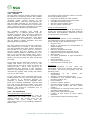
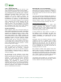
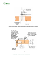
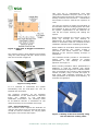
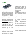
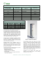
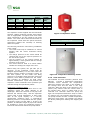
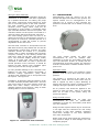
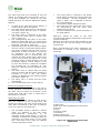
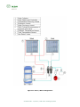
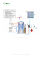
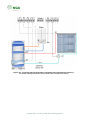
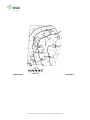
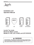
CI/SfB
41
Rq2
IRISH AGRÉMENT BOARD
CERTIFICATE NO. 12/0372
RVR Energy Technology Ltd.
Gortamullen, Kenmare, Co. Kerry .
T: 064 6641344
F: 064 6689520
E: [email protected]
W: www.rvr.ie
RVR Solar Heating Systems
Le système solaire de chauffage
Solarheizungssystem
NSAI Agrément (Irish Agrément Board) is designated by Government to issue European Technical Approvals.
NSAI Agrément Certificates establish proof that the certified products are ‘proper materials’ suitable for their intended
use under Irish site conditions, and in accordance with the Building Regulations 1997 to 2012.
USE:
The RVR Solar Heating Systems can be used in
new and existing buildings with a roof pitch of
between 25o and 70o. The collector must be fixed
to a roof that meets the requirements of I.S. ICP
2:2002 Code of practice for slating and tiling, and
prior versions of this document or previous Irish
codes of practice for slating and tiling. In
addition, all aspects of the Solar Heating System
shall be designed and installed to comply with SR
50-2:2011 Code of practice for building services
– Part 2: Solar panels (to be published).
PRODUCT DESCRIPTION:
This Certificate relates to RVR Solar HP collectors
and auxiliary system components.
The system is comprised of an RVR Solar HP
collector, a cylinder, pump station, control panel,
expansion vessel, connections, sloping roof kit,
antifreeze, user & installation instructions and
labelling packs.
The RVR Solar HP Collector consists of an
insulated manifold and a row of evacuated solar
tubes incorporating a Heat Pipe technology for
on-roof applications.
The RVR
Solar Heating Systems should be
installed by competent persons with suitable
training (including system specific training by the
Certificate holder) and practical experience of the
systems, and who have been approved by RVR
Energy Technology Ltd and NSAI Agrément to
install the system.
MARKETING, DESIGN AND MANUFACTURE:
The RVR Solar HP collectors are designed,
manufactured and tested by Jiangsu Sunrain
Solar Energy Co. Ltd. China. The solar kits are
designed and distributed by:
RVR Energy Technology Ltd.
Gortamullen, Kenmare, Co. Kerry .
T: 064 6641344
F: 064 6689520
E: [email protected]
W: www.rvr.ie
Readers are advised to check that this Certificate has not been withdrawn or superseded by a later issue by contacting
NSAI Agrément, NSAI, Santry, Dublin 9 or online at http://www.nsai.ie/modules/certificates/uploads/pdf/IAB120372.pdf
Part One /
Certification
1.1 ASSESSMENT
In the opinion of NSAI Agrément, the RVR Solar
Heating Systems, if used in accordance with this
Certificate can meet the requirements of the
Building Regulations 1997 to 2012, as indicated
in Section 1.2 of this Agrément Certificate.
1.2 BUILDING REGULATIONS 1997 to 2012
REQUIREMENTS:
Part D – Materials and Workmanship
D3 – Proper Materials
The RVR Solar Heating Systems, as certified in
this Certificate, are comprised of ‘proper
materials’ fit for their intended use (see Part 4 of
this Certificate).
D1 – Materials & Workmanship
The RVR Solar Heating Systems, as certified in
this Certificate, meet the requirements for
workmanship.
Part A - Structure
A1 – Loading
The
RVR
Solar
Heating
Systems,
once
appropriately
designed
and
installed
in
accordance with this Certificate, have adequate
strength and stability to meet the requirements
of this Regulation (see Part 3 of this Certificate).
Part B – Fire Safety
B4 – External Fire Spread
The RVR Solar Heating Systems will not affect
the external fire rating of the roof structure on
which they are installed (see Part 4 of this
Certificate).
Part C – Site Preparation and Resistance to
Moisture
C4 – Resistance to Weather and Ground
Moisture
The
RVR
Solar
Heating
Systems,
once
appropriately
designed
and
installed
in
accordance with this Certificate, will not affect a
roof’s resistance to the ingress of moisture (see
Part 4 of this Certificate).
Part L – Conservation of Fuel and Energy
L1 – Conservation of Fuel and Energy
The RVR Solar Heating Systems can be designed
to meet the minimum level of energy provision
from renewable technologies stated in this
Regulation
(for
domestic
dwellings),
i.e.
10kWh/m2/annum contributing to energy use for
domestic hot water heating.
Certificate No. 12/0372 / RVR Solar HP Heating Systems
1
Part Two /
Technical Specification and Control Data
2.1 PRODUCT DESCRIPTION
This Certificate relates to RVR Solar HP collectors
and auxiliary system components.
The RVR Solar HP collector has been tested to EN
12975-2:2006 Thermal solar systems and
components – Solar collectors – Test methods
2
Sunrain Solar Energy Co. Ltd. operate a 100%
inspection of their products which include
vacuum and stress testing of the evacuated
tubes and pressure testing of the copper HP
tubes and manifolds
2.1.1 RVR Solar Heat Pipe Solar Collector
The RVR Solar HP range of Collectors consists of
an array of evacuated ‘Sydney Tubes’ which
house the heat pipes and absorbers. Evaporator
fluid is contained within the heat pipe. The
energy absorbed by the absorber causes the fluid
to change from a fluid state to a vapour state
and the vapour rises to the condenser bulb.
The
solar
collector
mounting
frame
is
manufactured using profiled aluminium vertical
and horizontal sections. The manifold is made
from pressed aluminium. The header is insulated
using polyurethane (PU) foam. The heat pipe
condenser (bulb) 24mm diameter x
90mm
length is nickel coated to prevent “welding” of
heat pipe and heat pipe socket during high
temperatures operation.
The condenser is connected directly into the
manifold via a dry pocket. Within the manifold,
the solar system solution is passed across the dry
pocket that houses the condenser. The condenser
releases the latent heat of evaporation to the
solar system solution and condenses. The
condensate returns to the heat pipe and the cycle
is repeated.
2.3 DELIVERY, STORAGE AND HANDLING
RVR supply a full package for each solar heating
system installation, which includes the collectors,
cylinder, pump station, expansion vessel,
connections, antifreeze, stainless steel pipework,
connections, solar inhibitor – antifreeze, roof
mounting kit, control panel, user & installation
manual and labelling packs.
Due to the dry connection, RVR Solar HP tubes
can be replaced without the need of draining
down the solar system. Up to a maximum of 3 x
30 tube collectors can be joined together in
series with a flow rate of 5 litres/minute.
The following guidelines should be followed when
transporting
and
storing
solar
system
components:
• Solar collectors should always be stored
indoors.
• RVR Solar HP Collector Heat Pipe Tubes should
remain in their respective boxes in an upright
position during transport and storage.
• Cylinders should be transported and stored
vertically.
• All other solar system components should be
stored in a clean, dry, frost free environment
until ready for installation.
• Heavy goods should never be loaded on top of
solar collectors or kit boxes.
Figure 1:RVR Solar Heat Pipe Solar Collector
2.2
MANUFACTURE
The RVR Solar HP range of Collectors are
manufactured by Jiangsu Sunrain Solar Energy
Co. Ltd. in China. The management systems of
Sunrain have been assessed and registered as
meeting the requirements of ISO9001:2000.
Under conditions set out by the Solar Keymark
Certification, Sunrain Solar Energy are registered
and continuously monitored by Fraunhofer ISE,
Germany. Manufacture consists of fabrication and
assembly of the heat pipes, absorbers, manifolds
and evacuated tubes.
Parts should be inspected for damage on arrival
to site and any damages or losses should be
reported to the Certificate holder. Care should
be taken when opening kits to prevent scratches
or sudden shocks to the collectors and sharp
objects should not be used to open the
packaging.
Certificate No. 12/0372 / RVR Solar Heating Systems
2.4 INSTALLATION
2.4.1 General
The RVR Solar Collector Heating Systems should
be installed by competent persons with suitable
training and practical experience of the systems
(including system specific training by the
Certificate holder), who have been approved by
RVR and NSAI Agrément for this purpose. The
installer shall fully understand the requirements
of the customer and have completed a user and
installation health & safety risk assessment.
The necessary plumbing work should be
undertaken by a qualified plumber and the
necessary electrical work required to install the
control equipment, should be undertaken by a
qualified RECI electrical contractor. Solar panel
installations must be performed in accordance
with all Health & Safety legislation and local
building/planning regulations.
The solar collector must not be left exposed to
solar radiation prior to filling or when the solar
loop and manifold have been drained. Collectors
left exposed in a dry state must be covered to
prevent possible long term damage. The solar
collector system should be commissioned in low
light, or by covering the collector array, until it
has cooled down to a safe working temperature;
ideally in the morning when the solar loop should
be coolest.
Fixings used with the RVR Solar collectors, must
comply with Clause 4.11 and 5.9 of I.S. ICP
2:2002 and SR 50-2:2011 Code of practice for
building services – Part 2: Solar panels (to be
published).All tiles adjacent to the collectors
should be mechanically fixed in place. Flashings
used with the systems must comply with Clause
4.12 of I.S. ICP 2:2002.
In high wind load areas, identified during the
initial assessment survey, the truss design should
be checked by a Structural Engineer for
suitability, in relation to the applicable point
loads. Any resulting modification required shall
form part of the Structural Design report and
sign-off documentation issued by the Structural
Engineer. This should be completed prior to
commencement of work.
2.4.2 Pre-Installation
Sizing of the Solar Heating System
Minimising the risk of stagnation must be
considered by the installer when sizing a solar
heating system. The system must not be
oversized,
but
must
comply
with
the
requirements of Part L of the Building Regulations
1997 to 2012.
The following steps should be taken to correctly
size a solar heating system:
•
Determine the daily hot water demand.
•
Calculate the hot water heat requirement.
•
Calculate the storage volume.
•
Size the required collector area.
•
Size the system components.
Sizing of Safety Equipment
Component sizes are relative to the volume of
liquid in the system and the RVR Solar Technical
Information and Installation Instructions should
be consulted for each system.
Risk Assessment
Before work commences on the installation, a
risk assessment must be completed and recorded
by the installer. Items assessed include:
•
Access to roof.
•
Ability of roof structure to accommodate all
applied loadings.
•
Working at height.
•
Effects of wind and snow loads.
•
High temperature pipe work and liquids.
•
Antifreeze storage and discharge release.
•
Water quality.
•
Fire safety (installation of high temperature
components).
•
Risk of legionella.
•
Access for routing pipework.
•
Protection from overhead wires.
Site Survey
Following
completion
of
the
initial
risk
assessment, a site survey must be carried out by
the installer. This survey will typically cover the
following points:
•
Identification
of
any
special
user
requirements.
•
Shading (current and potential risk).
•
Suitability of roof (collector fixing surface,
tile/slate condition etc).
•
Roof orientation.
•
Access to collector location.
•
Pre-heat storage location- is there adequate
space for DHW cylinder and solar control
system)..
•
Configuration of occupants DHW system and
anticipated usage patterns.
•
Sizing of the solar heating system.
•
Location of and access to pump station
assembly.
•
Control panel location and fixing height.
Certificate No. 12/0372 / RVR Solar Heating Systems
Figure 2: Main components of the RVR Solar Heating Systems
Further guidance on various configurations of the heating side of the system such as
open versus closed systems are available in RVR technical literature.
Certificate No. 12/0372 / RVR Solar Heating Systems
Table 1:Power Output Per Collector Unit .
Global Irradiance (G)
Tm-Ta 1/
G = 400 W/m2
1/ 2/
G = 700 W/m2
G = 1,000 W/m2
HP10
HP30
HP10
HP30
HP10
HP30
10K
259
772
465
1387
671
2001
30K
218
650
424
1264
630
1879
50K
164
490
371
1105
577
1719
1/
G, Tm (mean temperature of system fluid), Ta (ambient temperature) and performance values per I.S. EN 12795-2:2006–
Fraunhofer Institute Test report: KTB Nr.2007-07-aq-en-k.
2/
Above values for are based on output from the RVR Solar HP 10 and 30 (10/30 tube set – smallest & largest collector of
series).
Table 2:Characteristics of RVR Solar Collectors. 2/
Type
Dimensions
HP10
Heat Pipe
1.8mx0.058m Tube length x outer
dia.
HP30
Heat Pipe
1.8mx0.058m Tube length x
outer dia.
Height/Depth
Gross Area
Total Weight - empty
Liquid Volume
Flow rate
189 mm
1.715 m2
39.6 kg
0.7 litres
0.5 to 1.5 l/min per m2 of aperture
189 mm
4.901m2
106kg approx.
2.3 litres
0.5 to 1.5 l/min per m2 of
aperture
Absorber shape
Aperture Area
Absorber Area
Absorption
Emission
Max Stagnation Temperature
Max Operating Pressure
Efficiency Constants for G=8000W/m2
(Aperture Area) 1/
Cylindrical
0.936 m2
0.808 m2
94%
7%
200.3oC
10 bar
Cylindrical
2.791m2
2.411 m2
94%
7%
200.3oC
10 bar
η0 = 0.734
a1 (W/m2K ) = 1.529
η0 = 0.734
a1 (W/m2K ) = 1.529
Casing/Manifold Material
Absorber Material
+ Coating
Aluminium (Extruded)
Aluminium
+ ALN/SS-ALN/Cu
Aluminium (Extruded)
Aluminium
+ ALN/SS-ALN/Cu
Flowed Through Element
Glazing / Thickness
Copper Pipe
Borosilicate glass / 1.8mm (outer
tube)
Copper Pipe
Borosilicate glass / 1.8mm
(outer tube)
Insulation Material
Heat Transfer Fluid
Mineral Wool (40mm)
Water-Propylene glycol mix
Mineral Wool (40mm)
Water-Propylene glycol mix
a2(W/m2K) = 0.0166
1/
a2(W/m2K) = 0.0166
η0 (zero-loss collector efficiency), a1 (heat loss coefficient), and a2 (temperature dependence of heat loss
coefficient values from tests carried out in accordance with I.S. EN 12795-2:2006 Fraunhofer Institute Test
report :KTB Nr.2007-07-aq-en-k.
2/
Specified data based on the smallest and largest collector in the Series – 10 & 30 tube set (RVR Solar HP)
Certificate No. 12/0372 / RVR Solar Heating Systems
2.4.3 Sloping Roof Kit
The Certificate holder defines the roof kit to be
used, depending on the collector being installed
and the type of slate/tile used. All roof brackets
are manufactured from stainless steel. Isolation
gaskets shall be used where necessary to ensure
bi-metallic corrosion does not occur. The
collectors and fixing bracket systems are
designed to cover all Irish wind zones (as
illustrated in Figure NA.1 in Irish National Annex
to Eurocode 1). However, in high wind load
areas, e.g. at excessive heights or very exposed
areas, additional roof fixing brackets may be
required. The advise of the Certificate holder
shall be sought in all such instances, or if doubt
exists. See Cl. 3.1 of this Certificate for details of
the mechanical load and wind up-lift testing
performed on the RVR range of HP collectors.
Noggin Installation
Solar collectors shall not be secured directly to
rafter timbers and shall only be fixed via noggins
to meet the requirements of SR 50-2: 2011 Code
of practice for building services – Part 2: Solar
Panels (to be published). Noggins (100x75 mm
C14 grade timber) are suitably located and
secured between the rafters using angle brackets
(supplied by RVR) and 4 No 3mm Ø *30mm
galvanised nails or screws (minimum shank
diameter 4mm) per leg as shown in Figures 3 5. The hanger bolt is then located in the centre
of the noggin with a minimum 40 mm on either
side of the penetration and a minimum 115mm
from the edge of the noggin.
The support system and fixings, when installed,
shall be designed and constructed so that the
roof complies with the relevant
technical
specifications for the use of structural timber:
I.S. EN 1995-1-1:2005 Eurocode 5 – Design of
timber structures – General – Common rules and
rules for buildings.
An assessment of the condition of the rafter
timbers is part of the site survey report. Any
timbers showing signs of damaged or rot must be
replaced. In high wind load areas, identified
during the initial assessment survey, the truss
design should be checked by a Structural
Engineer for suitability in relation to the
applicable point loads. Any resulting modification
required shall form part of the Structural design
report and sign off documentation issued by the
structural engineer. This should be completed
prior to commencement of works.
RVR Solar HP- On-roof installation
The complete procedure for the installation of the
RVR range of on-roof HP collectors is detailed in
the RVR Solar Installation Instructions. Stainless
Steel hanger bolts are used to secure the panels
to the roof.
The roof is measured to establish the collector or
array position. In order to minimise suction force
caused by wind loads, the distance between the
outer edge of the roof and the collector should be
500mm (about 3 tiles). The distance from the
roof ridge should be approximately 2 tile rows.
Stainless Steel Hanger bolt
At each identified location a 6mm hole
is carefully drilled out through the centre of the
noggins (minimum size 100mm x 75mm)
through into the tile or slate. When all pilot holes
have been drilled, 11mm clearance holes are
drilled through the tile/slate only.
It at all possible the holes should be drilled in
the middle of the tiles/slates, so that only
one tile/slate has to be drilled. Noggins to be
located accordingly. The hanger bolt is then
secured penetrating at least 60mm into the
noggin.
Soudaseal Stock No SOL100 adhesive sealant
(supplied in the kit) is applied to the surface
around the bolt. The neoprene washer is fitted
followed by the SS nut. The nut should be
tightened by hand and then given one full turn to
form a watertight seal. Care should be taken not
to over tightened the nut due to the risk of
breaking the slate or roof tile.
More adhesive sealant then applied around the
washer and nut to give extra weather protection
and prevent loosening. Another SS nut is
screwed on the protruding bolt and a small space
left between the first and second nut. A further
nut is used to fasten the slotted stainless steel
tab onto the hanger bolt. Refer to Figure 3.
The bracket cross members are now fitted to the
slotted stainless steel tab using the M10 x 20mm
screws, washers and nylock nuts provided.
Certificate No. 12/0372 / RVR Solar Heating Systems
Figure 3: Fixing Detail – Noggin, Stainless Steel Hanger Bolt and Cross Member.
Figure 4: Side Elevation of Noggin Connection to Rafter
Certificate No. 12/0372 / RVR Solar Heating Systems
This vent tile is manufactured from ABS
(Acrylonitrile Butadiene Styrene) and is AA fire
rated when tested to BS 476-3:2004 Fire tests on
building materials and structures – Classification
and method of test for external fire exposure to
roofs.
The vent tile will have a design life equivalent to
the RVR Solar Collector Heating System and must
be inspected as part of routine maintenance on
the system. Replacement of the Glidevale G1
vent tile will require draining and refilling the
system.
Where pipes penetrate the interior of the attic
space, e.g. through the roof underlay or
plasterboard, all resulting penetrations must be
sealed in accordance with the Certificate holders
installation manual before completing the work.
Figure 5: Plan View of Noggin Connection to
Rafter
The collector frame is then fastened into position
using the metal clamps and M8 x 40mm screws
and nuts as shown in Figure 6.
When installed in accordance with the Certificate
holder’s instructions, this system creates a
permanent seal which ensures the weather
tightness of the external building envelope is
maintained.
The Certificate holder provides a self adhesive
sealing collar Code: SOL235 for sealing
perforations in the underlay to facilitate
pipework. See Figure 7.
Where existing insulation and/or plasterboard is
displaced, it must be replaced with similar
material and made airtight. The Certificate holder
also recommends the Proclima (IAB Certificate
number 07/0297) range of seals and tapes or
Siga range (IAB Certificate 08/0314) to seal
other perforations in the fabric of the building to
maximise air tightness.
Figure 6: Fixing Detail
If it is intended to commission the system
immediately then the heat-pipes can now be
installed into the header.
The complete procedure for the assembly
and installation of the RVR Solar HP Collector
frame
are
detailed
in
the
RVR Solar
Installation Instructions. The mounting frame
for the RVR HP collector is assembled on site
and fixed directly to the installed roof fixings.
2.4.4 Roof Penetrations
The Certificate holder supplies the Glidevale G1
vent tile (See Figure 8) for use with the full range
of RVR on-roof HP collectors, for carrying pipes
through the roof into the attic space.
Figure 7: Sealing of the Roof Underlay using
the self adhesive sealing collar .
Certificate No. 12/0372 / RVR Solar Heating Systems
Figure 8: Glidevale G1 Vent Tile
2.4.5 Connections
In any solar heating system, the ‘return’ refers to
the intake in the collector where liquid is
returning to be reheated. The ‘flow’ refers to the
hot outflow side where the liquid is flowing to the
heat exchanger. It is essential that the collector
temperature sensor is located in the flow line of
the collector. All copper pipework should meet
the requirements of I.S. EN1057:2006+A1:2010:
Copper and copper alloys – Seamless round
copper tubes for water and gas in sanitary and
heating applications and be clearly marked in
accordance with BS 1710:1984 Identification of
pipelines and services. Ideally, pipes should take
the shortest route to the solar store and always
slope back to avoid air locks from the collector to
the pump station.
All solar pipework should only be secured with
metal pipe clips. Plastic clips can not withstand
the higher temperatures generated by Solar
Heating Systems and must never be used.
Flexible Pipe Connections
Flexible pipe connections are required to connect
the manifold through the building fabric and
allow flexibility in connecting to the internal pipe
work. Flexible stainless steel pipes are available
in 12mm, 15mm, 16mm 20mm and 25mm
diameter. If connecting one diameter pipe to
another, a suitable reducer compression fitting is
required to make the connection.
Types of Connections
The only pipes which should be used with a solar
installation
are
copper
pipe
(to
I.S.
EN1057:2006+A1:2010),
continuous
flexible
stainless steel or mild seamless steel pipe (to ISO
9329-1:1989: Seamless steel tubes for pressure
purposes – Technical delivery conditions – Part 1
Unalloyed steels with specified room temperature
properties. When using copper pipe, only
compression fittings or brazed joints (at 900oC)
can be used. Soft Solder joints are not suitable
for solar installations.
Pipe work Insulation
All pipe work on the solar loop shall be insulated
with high temperature insulation suitable for use
at
temperatures
above
150oC,
such
as
HT/Armaflex or equivalent. This is essential as
regular
pipe
insulation
will
degrade
at
temperatures experienced by solar pipes. The
wall thickness of the insulation should be at least
equal to the diameter of the pipe and must
conform to the requirements of Cl 1.4.4 of TGD
Part L to the Irish Building Regulations. The only
pipes which should not be insulated are the pipes
to the safety vessel, as they should allow heat to
dissipate when the system is experiencing
excessive heat and pressure.
2.4.6 Cylinder
Consideration should be given to the load bearing
requirements of the Cylinder and the space
required to house the solar cylinder, pump
station and associated expansion vessel, valves
and pipework, with regard to installation,
inspection and maintenance.
The Certificate holder supplies the WRAS
approved range of RVR solar Cylinders. The RVR
solar cylinders are stainless steel twin or triple
coil cylinders for use in pressurised or vented
systems and have been developed specifically for
solar applications. See Figure 9 and Table 4.
A twin coil hot water storage cylinder enables
energy input from the central heating system to
the top half of the tank, and energy input from
the solar heating system to the bottom half of
the tank.
When installed on a pressurised system the
cylinder and associated safety devices must be
installed and commissioned by a qualified and
certified plumbing heating engineer. Solid fuel
heating systems must not be incorporated into a
pressurised heating system.
In addition, other DHW cylinders may be used,
provided they have NSAI Agrément Certification
for use with this system.
See Table 3 for the full range of compatible
Combination Cylinders which can be used in
conjunction with the RVR Solar Heating Systems.
The FS and Proclean are combination tanks for
domestic water and central heating. The main
body of the cylinder contains heating water while
the high surface area stainless steel coil through
the centre of the cylinder contains the domestic
hot water.
Note: PEX/Plastic/PEX-ALU-PEX or galvanised
tubing or fittings should NOT be used under any
circumstances.
Certificate No. 12/0372 / RVR Solar Heating Systems
Table 3: RVR – Cylinder Compatibility
Combination Cylinders Product Codes
Number of Adults
(+ Central Heating)
4 to 8
5 to 9
6 to 10
6 to 10
7 to 11
8 to 12
2 to 4
4 to 8
5 to 9
6 to 10
5 to 9
6 to 10
RVR Solar HP collector
(Approx)
Cylinder Type
Proclean 500
Proclean 800
Proclean 1000-B
Proclean 1000-S
Proclean 1250
Proclean 1500
FS-1R 375
FS-1R 500
FS-1R 800
FS-1R 1000
FS-2R 800
FS-2R 1000
Product Code
60 - 80 Tubes
ASK120
60 – 90 Tubes
90-120 Tubes
90-120 Tubes
120 – 150 Tubes
150 Tubes
30 - 50 Tubes
60 - 80 Tubes
60 – 90 Tubes
90-120 Tubes
60 – 90 Tubes
90-120 Tubes
ASK121
ASK122
ASK123
ASK124
ASK125
ASK139
ASK140
ASK141
ASK143
ASK142
ASK144
Table 4: RVR Solar Cylinders Product Codes
Number
of Adults
Cylinder Size
RVR Solar HP
collector
2-4
2-4
3-6
3-6
4-8
5-9
200 Litre
250 Litre
300 Litre
300 Litre(Triple Coil)
400 Litre
500 Litre
20
30
30
30
50
60
-
30
40
50
50
60
80
Product Code
Tubes
Tubes
Tubes
Tubes
Tubes
Tubes
AMS900
AMS902
AMS905
ASK303
AMS907
AMS909
In the FS tank, a solar heating coil is located in
the coolest water at the bottom of the tank.
In the Proclean tank, when solar heating is used,
an optional solar coil attached to the side of the
cylinder will deliver the solar energy high in the
cylinder. The DHW is fed from a coil in the centre
of the tank. The corrugated profile of this
Stainless Steel coil creates a large heat exchange
surface and generates strong eddies reducing the
risk of legionella formation. See Figure 21.
The sizing for the combination cylinders is shown
in Table 3 above. This sizing is approximate, as it
will vary on heating demand as well as the
demand for DHW. They must be sized according
to the individual requirements.
Cylinder storage size is calculated at twice the
household’s hot water demand, which is
estimated at 50 litres/adult/day. The Certificate
holder recommends a 200 litre cylinder for a one
to three adult household, and a 300 litre cylinder
for three to five adults.
All hot water storage vessels should carry a label
containing the following information.
- Manufacturers name
- Nominal capacity in litres
- Standing heat loss in kWh/day
- Type of vessel
- Auxiliary heating heat exchanger performance
in kW (where present)
Figure 9: RVR solar Cylinders
A thermostatic mixing valve (TMV) set at 45oC
shall be installed with the RVR Solar heating
systems to prevent accidental scalding to the
householder. In short pipe work runs without
dead legs, where the legionella risk has been
assessed to be minimal, the mixing valve can be
located at the hot water outlet from the cylinder.
Where a legionella risk has been assessed to be
high, insulated recirculation pipe work should be
installed and individual thermal mixing valves
fitted to each of the hot water taps.
Insulation of the cylinder must comply with
Clause 1.4.4 of TGD to Part L of the Building
Regulations 1997 to 2012.
Certificate No. 12/0372 / RVR Solar Heating Systems
2.4.7 Solar Pump Station
The RVR solar system is managed by the FlowSol
S pump station. This pump station incorporates a
solar circulating pump with a 6m head, and flow
isolation valves. The flow rate required on a
system is typically 0.5 to 1 litre/minute per
square metre of aperture installed.
Therefore, a 1-13 litre pump station will be
sufficient for systems up to 12m2 providing pipe
work diameter, head and component losses have
been calculated correctly.
The following connections need to be made to the
solar pump station:
• Flow and return lines linking the solar collector
and storage tank.
• Expansion vessel connection – Which includes
a flexi pipe, wall bracket and check valve.
• Connect discharge from pressure relief valve
to suitable drainage.
• Container so that the householder is aware
when solar fluid has been lost and how much
was lost.
All pipework connections to the pump station are
made with flat faced compression fittings to
connect to stainless steel pipework.
The RVR pump station must be fixed to a sound
surface, suitable for holding the weight of the
unit and should be in an accessible location and
not obstructed or concealed to allow for easy
inspection, maintenance and/or replacement.
Table 5: Solar Pump Station Product Codes
Flow rates
l/min
Product
Code
1-13
SOL053
1-13
ASK001
System
Standard (Deltasol C4
Controller & FlowSol S6
Pump Station)
East/West (Deltasol Plus
Controller & Flowcon Twin
Pump Station)
2.4.8 Safety Vessel Connections
Pressure Relief Valve (PRV)
Rated at 6 bar, the Pressure Relief Valve (PRV)
may discharge heat transfer fluid which must be
channelled
into
a
container
capable
of
withstanding high temperature discharge and
containing 1.5 times the total collector volume.
RVR offer a discharge container, with a volume of
9.6 litre (Stock no SOL143) which must be
secured so it cannot be removed or spilled and
located to facilitate drainage if required. See
Figure 11. The PRV must not be channelled into a
drain or any pipe work which will allow it to enter
the normal water course.
All safety control valves should be readily
accessible and verifiable in operation, particularly
during commissioning and maintenance.
Figure 11: Discharge Container
Expansion Vessel
The certificate holder supplies the TiSUN or
Varem solar expansion vessel with the RVR Solar
Heating Systems. See Table 6 and Figure 12.
The vessels are pre-charged to 2.0 bar and have
maximum rated pressure of 10 bar for the TiSUN
and 8 bar for the Varem solar expansion vessel.
Figure 10: Pump station
While the vessel membrane can tolerate
temperatures of 100oC, it is recommended to fit
the vessel at least 500mm below the level of the
connection from the pump station to prolong its
life. If this is not possible, an intermediary
Temperature Reducing Vessel should be installed
between the pressure vessel and pump station.
Certificate No. 12/0372 / RVR Solar Heating Systems
Table 6: Expansion Vessel - Product codes
Vessel
(litre)
Product
Code
Manufacturer
19 litre
25 litre
33 litre
40 litre
80 litre
SWH170
SOL786
SOL787
SWH172
SWH174
Varem
TiSUN
TiSUN
Varem
Varem
Charge
Pressure
(bar)
2
2
2
2
2
The expansion vessel supplied with the RVR Solar
Collector Heating Systems includes wall bracket
and an appropriate corrugated hose and clutch
valve connection to join the vessel to the pump
station. The clutch valve allows disconnection of
the expansion vessel after the system has been
pressurised without the necessity of draining
down the system.
System
Pressure
(bar)
2.2
2.2
2.2
2.2
2.2
Figure 12: Expansion Vessel
Table 7: Temperature Reducing Vessel
- Product code
Vessel (litre)
18 Litre
Product Code
SWH169
The following should be noted during installation
of the vessel:
• The vessel must only be installed in a vertical
position with the vessel connection facing
upward.
• The charge pressure of the vessel should be
checked and set at the required pressure for
the size of the system.
• The fill pressure of the system should be
approximately 0.2 bar greater than the charge
pressure of the vessel.
• The vessel shall be fixed to a sound surface
suitable for holding the weight of the unit.
Before filling the system, the gas side (air or
nitrogen) of the expansion vessel must be
charged approximately 0.2 bar lower than the
intended cold fill pressure (normally 2.2 bar), of
the solar system. As the initial cold filling
pressure is set slightly higher than the vessel gas
pressure, some fluid is pushed into the vessel.
This provides an allowance for fluid losses
between maintenance cycles and protects the
expansion vessel membrane from potential jets
of steam during the operational phases.
Temperature Reducing Vessel
Long periods of high temperature fluid in the
expansion vessel can cause damage to its
diaphragm. When the contents of the pipe work
between the collector array and the expansion
vessel (with a fixed membrane) is lower than
50% of the liquid capacity of a correctly
dimensioned expansion tank, a Temperature
Reducing Vessel is incorporated into the system
as shown in Figure 13 and Table 7. If this is not
possible, an adequate length of pipe work should
be installed to ensure the Expansion Vessel is
located at least 500mm below the pump station.
Figure 13: Temperature Reducing Vessel
2.4.9 Solar Controller
The DeltaSol C4 Solar Controller (Product Code
SOL147)
includes a differential temperature
controller which monitors the temperature
difference between the water in the bottom of
the storage tank and the fluid in the solar
collectors. When the fluid in the collectors is 6oC
(factory set) warmer than the coolest water in
the storage tank, there is usable heat to be
collected. The controller starts the pump and
when the temperature difference drops to within
4oC (factory set), the controller stops the pump.
The pump remains off until a useful temperature
difference exists again. The installer can change
the factory settings for starting and stopping the
pump.
Certificate No. 12/0372 / RVR Solar Heating Systems
Wiring the Solar Controller
All electrical aspects of the installation should be
undertaken in accordance with ETCI regulations
by a qualified electrician. For safety, the pump
and sensor connections should always be wired
prior to connecting power to the solar controller.
The solar controller must have a permanent
electrical power supply which must not be
interrupted by a time switch. A switchable fused
spur with LED should be used for the system. The
controller should not have power connected to it
until the system has been filled with solar fluid.
The solar heating system does not have to be
drained if the power is disconnected. However, if
the system is unused for extended periods it is
recommended to drain the system to prevent
degradation of the anti-freeze.
The RVR solar controller is incorporated into the
RVR Solar Flowsol S pump station but can also be
independently located when required. The solar
controller should be located in a prominent
location that is readily accessible and frequently
occupied, normally on the landing outside the
solar store, fixed not less than 1.5m above floor
level. The controller display should be readily
visible at all times with clear access and not
concealed or obstructed. In order to protect the
normal operation of the controller, it should be
located at least 100mm from insulated pipes
which may become hot during operation.
To limit potential damage to the controller from
lightning via the solar collector thermostat, a
transient voltage suppression (TVS) diode
(Product Code: SOL255) can be incorporated into
the system. See Figure 15.
In addition, all pipework shall be bonded in order
to avoid electrical potential differences. The flow
and return pipes to the solar collector should be
fitted with earth clamps, connected to the
earthling system of the property, using an earth
bonding cable of 10 mm2 minimum.
2.5 COMMISSIONING
Commissioning must be carried out by the
trained and approved installer of the system. The
system should not be commissioned if the
collectors are in excess of 60oC because the
pressures recorded will not be stable in the long
term.
Figure 15: RVR TVS Diode
The solar system should be filled and
commissioned as soon as possible after
installation to avoid any unnecessary heat build
up in the collectors. If there is a delay with the
commissioning of the solar system, the collectors
must be covered with a suitable weather and UVproof cover.
Expansion Vessel
Prior to filling the system, the expansion vessel
pressure must be set 0.2bar below the system
pressure.
The pressure is checked at the base of the
expansion vessel and the bleed valve may be
bled or topped up with a pump. Omitting to
perform this check will result in irregular pressure
readings during the operation of the system.
An air pressure test should be applied to the
system to check for leaks. Once it is clear that
there are no leaks in the system, filling can
proceed as follows:
Filling the Solar Circuit
The solar system should be filled and
commissioned
as
soon
as
possible after
installation to avoid any unnecessary heat build
up in the collectors.
Filling the solar system should only be carried out
in low light when the collectors are cool. Filling
the system in high solar radiation conditions
could cause damage to the solar collectors
and other components.
Figure 14:
DeltaSol C4 Solar Controller
Water must not be used to flush the system as it
may present a danger of frost damage if it is not
completely purged.
Certificate No. 12/0372 / RVR Solar Heating Systems
The solar fluid must not be diluted as this will
change its freezing point and viscosity. See Cl.
3.5 of this Certificate for details of the heat
transfer fluids for use with the RVR Solar Heating
Systems.
1.
2.
3.
4.
5.
6.
7.
8.
An RVR 8 bar solar filling pump station is
used to purge and fill the system.
The filling pump supply hose is connected to
the filling valve and the valve is opened.
(see item 4 Figure 16)
The drain hose is connected to the drain
valve and the drain valve is opened. See
item 2, Figure 16.
The commissioning ball valve on the solar
station is closed. Ball valve 3 is turned to lift
the non-return valve and allow fluid to enter
the pump. (see item 3, Figure 16)
Sufficient solar fluid for the system is added
into the reservoir of the filling pump station.
The pump is started and the solar circuit is
flushed for at least 15 minutes. To get the
air completely out of the system, the
commissioning valve is opened after five
minutes and then closed again. Water must
not be used to flush the system as it may
present a danger of frost damage if it is not
completely purged. Correct purging of the
air from the system is critical as it negates
the necessity for an Automatic air vent
(AVV) for continued correct operation of the
system.
The Drain Valve is closed while the filling
pump is running and the system pressure is
increases to circa 3 bar. The system
pressure is displayed by the pressure gauge
(see item 6 Figure 16.
The filling valve is closed and the pump
switched off.
The commissioning valve is then opened.
•
•
•
•
The pump speed is reduced to the lowest
speed which permits the required flow rate
to be obtained. The flow regulating valve
(item 9, Figure 16) is adjusted to achieve
the correct flowrate.
The system is again checked for leaks.
The hoses from the filling and drain valves
are disconnected and the screw caps
attached to the valves.
The front insulated cover is then mounted on
the solar station.
Reference should be made to the RVR
controller/solar station instructions for the full set
of system settings.
Selecting the lowest pump speed possible to set
the flow rate will use less energy and operate
much quieter.
Once commissioning has been completed, the
information is recorded on the Commissioning
Certificate.
Setting of the System Pressure
The system pressure must be set to 2.2 bar for
correct operation. Some fluid can be drained via
the drain valve to reduce the pressure to the
correct level. Ball valve (item 3- Figure 16) is
turned back to vertical.
Setting the Flow Rate
To ensure the optimum transfer of solar energy
from the collectors to the storage tank, the
correct flow rate for the solar circuit needs to be
used. RVR recommends a flow rate of between
0.5 to 1.0 l/min per m2 of aperture.
•
The circulation pump is started in manual
mode (as specified in the RVR Solar
station/controller
instructions)
at
its
maximum pump speed setting. It may be
necessary to bleed the circulating pump by
unscrewing the brass screw on the pump
face. This brass screw must be replaced
once the pump has vented.
1
2
3
4
5
6
7
8
9
Controller
Drain Valve
Ball valve with integrated non-return valve
Fill valve
Pump
Pressure gauge
Flowmeter
Safety Valve 6 bar
Flow/commissioning valve
Figure 16: Filling Valves/Flow Rate
Adjustment
Certificate No. 12/0372 / RVR Solar Heating Systems
Final Commissioning Requirements
•
The installer must complete two copies of the
Commissioning Certificate. One copy is left
with the customer in the User Manual and the
second copy is kept by the installer.
•
The installer must complete the Maintenance
Log (with system description) and locate it in
a viewable position, e.g.
attached to the
expansion vessel or pump station.
•
The HOT PIPE warning labels (x2) are affixed
to the cylinder flow and return lines.
•
The installer shall hand over the User Manual
to owners, and instruct users on all aspects
of the documentation and how to effectively
use the solar equipment.
Upon commissioning and periodically, i.e. during
annual maintenance, the sight glass on the solar
station must be checked for bubbles of air. This
will indicate the existence of air in the system.
The solar circuit must be purged when this occurs
to rid the system of air.
User Manual
The user manual includes information on the
basic control functions, parts of the system,
recommended maintenance schedule, and full
contact details of the installer and the system
designer/certificate holder.
Decommissioning the System
The pipework and panels must be cool, before
working on the system. Decommissioning should
only be attempted when there is no solar input,
or the panels should be covered with light proof
covers and left for at least 5 hours. The solar
fluid must be drained down and disposed of
correctly, do not drain into public sewer. Disposal
of any equipment and materials from the system
must be performed in accordance with the
Certificate holders instructions. Panels should
only be removed by qualified professionals using
appropriate access and safety equipment.
2.6 MAINTENANCE
The RVR Solar Collector Heating Systems should
be maintained by competent persons with
suitable training and practical experience of the
systems.
Cl. 3.5 of this Certificate lists the Heat Transfer
Fluids to be used with the RVR Solar Heating
Systems, which provide frost protection to as low
as -25°C The level of frost protection in a solar
system should be checked annually using a
refractometer.
A pH test should be carried out on the solar fluid
annually to check the level of acidity. If the level
drops below 7 on the scale, the glycol should be
changed. Frequent overheating of the solar fluid
(stagnation) causes the glycol to disintegrate into
acids, leading to corrosion of the solar collector
pipe work.
RVR recommends that the following checks are
undertaken annually on the solar system:
•
•
•
•
•
•
•
•
•
•
Check of the solar circuit, tank and pump
station for leaks.
Check of solar system pressure. If pressure
drop is detected, the system is topped up
with glycol anti-freeze and re-pressurised as
specified in Cl. 2.5.
Inspection of external pipe insulation for
damage, degradation or contamination.
Visual inspection of solar collectors for
evidence of damage. Collectors should be
cleaned as required using a soft cloth to
maintain the efficiency of the system.
Change any broken vacuum tubes. A broken
vacuum tube does not prevent the system
from running but it will cause some loss of
efficiency
Inspection of mounting fixtures and fastening
screws for evidence of looseness or damage.
Tighten/replace as necessary.
Test of the glycol anti-freeze fluid (for the ph
level/freezing point - replace as necessary.
Check on charge pressure of all expansion
vessels and recharge as necessary.
Check
of
circuit
flow
rate
(against
commissioning card recorded setting) and
adjust as necessary.
Check of circulating pump for noise/damage.
For any other queries or anomalies regarding
maintenance
and
troubleshooting,
the
Certificate
holder/installers
should
be
contacted.
2.7 RETROFITTING/REPLACING
The RVR range of HP collectors can be retrofitted
to existing roofs. During the pre-installation
survey, special attention must be given to the
condition of the existing roof structure and its
ability to take the additional applied loadings of
the collector as described in the RVR Energy
Solutions Risk Assessment and Site Survey
assessment procedures.
Should the collector require replacing, the system
shall be drained, collector replaced and the
system filled and commissioned as detailed in Cl.
2.5 of this certificate.
Certificate No. 12/0372 / RVR Solar Heating Systems
Figure 17: East / West Configuration
Certificate No. 12/0372 / RVR Solar Heating Systems
Figure 18: Two Tank System
Certificate No. 12/0372 / RVR Solar Heating Systems
Figure 19: Heat Dump Facility
Certificate No. 12/0372 / RVR Solar Heating Systems
Figure 20: FS Cylinder System
Certificate No. 12/0372 / RVR Solar Heating Systems
Figure 21: Proclean Cylinder System
Certificate No. 12/0372 / RVR Solar Heating Systems
Figure 22: Controller Wiring Schematic (including Anti-Legionnaires function).
For detailed wiring information refer to RVR solar controller instructions
Certificate No. 12/0372 / RVR Solar Heating Systems
Part Three /
Design Data
3.1 STRENGTH AND STABILITY
RVR Solar HP collector
The RVR Solar HP collector was tested to 1000 Pa
positive pressure (i.e. downward pressure)
without failure occurring. Using the safety factor
of 1.5 for positive pressure, the RVR Solar HP
collectors can be deemed to withstand a positive
pressure of up to 666 Pa.
The negative pressure (uplift) test was not
conducted as any negative pressure on the fixing
between the vacuum tubes and the casing are
deemed to be negligible.
General
The collectors and fixing bracket systems (as
detailed in Cl. 2.4.3 and Figures 3 - 5) are
designed to cover all Irish wind zones (as
illustrated in Figure NA.1 in Irish National Annex
to Eurocode 1). However In high wind load areas,
e.g. at excessive heights or very exposed areas,
wind loads should be calculated in accordance
with I.S. EN 1991-1-4 Eurocode 1 – Actions on
structures – General actions – Wind actions as
additional roof fixing brackets may be required.
The advice of the Certificate holder should be
sought regarding any query related to loads
acting upon the solar collector and its fixings.
To minimise the effect of wind load on the
collectors, it is recommended that collectors are
not installed within 0.5m of the roof edge, ridge,
eaves or projections such as parapets, chimneys
or dormer windows.
The host roof structure, and any modifications
necessary to accommodate the RVR Solar
Heating Systems, should be checked by a
suitably qualified engineer in accordance with the
Building Regulations 1997 to 2012. The installer
of the system must ensure that this has been
done prior to commencing installation. Fixings
used with the RVR Solar collectors, must comply
with Clause 4.11 and 5.9 of I.S. ICP 2:2002 and
SR 50-2:2011 Code of practice for building
services – Part 2: Solar panels (to be published).
3.2 IMPACT RESISTANCE
RVR Solar HP collector
When tested for impact resistance in accordance
with EN 12975-2:2006 Cl.5.1 (Method 1) the RVR
Solar HP collector sustained no damage when
impact tested using a 150g steel ball up to a
height of 0.8 m.
3
3.3 COLLECTOR EFFICIENCIES
The ability to convert solar energy into thermal
energy is expressed by the optical efficiency, η0,
(zero-loss collector efficiency in SEAI DEAP
software) of the system. Table 1 shows the η0
values for the RVR Solar Collectors when tested
to EN 12975-2:2006.
At high levels of sunlight (1000W/m2), when the
average system fluid temperature is slightly
higher than ambient temperature (10K), system
utilising the RVR collectors can transfer
approximately 2 kW of energy for the Solar HP
collector collector (based on the Solar HP – 30
tube set) to the building hot water store. Test
results of the performance of the collectors are
shown in Table 1 and 2.
3.4 RISK
OF
BACTERIAL
GROWTH
/
LEGIONELLA
The installer of the RVR Solar Heating System
completes a Legionnaires Checklist as part of the
initial risk assessment of the site during the preinstallation survey. If a risk of legionella is
identified during this risk assessment a
supplementary relay (connected to an auxiliary
heating source), activated by the control
panel, is installed. Guidance shall be sought
from the Certificate Holder in all such instances.
When this function is activated, the cylinder is
heated to 60oC utilising the immersion heater or
boiler, at a frequency set by the timer (daily for
cylinders with a capacity of over 400 litres).
Scald out time, set by the installer, is dependent
on the cylinder temperature and volume. See
Figure 22.
RVR also offer a range of Proclean tanks, which
incorporate corrugated profiled Stainless Steel
coils. These coils generates strong eddies
reducing the risk of legionella formation. See
Figure 21 and Table 3.
In addition, a thorough review of all pipework is
required in such situations with alterations
incorporated as required to limit risk.
Information and guidance is provided to the
homeowner by the installer on the correct
operation of the solar heating system during
normal operation and after periods of non-use, to
help reduce the risk of legionella.
Certificate No. 12/0372 / RVR Solar Heating Systems
Examples of areas where a risk of legionella may
be identified include long periods of non-use of
the hot water supply, infrequently used outlets
such as showers and taps, and residents who are
highly vulnerable to infection. For further
guidance, refer to the HPSC (Health Protection
Surveillance
Centre)
document
National
Guidelines for the Control of Legionella in Ireland
and the NDSC (National Disease Surveillance
Centre)
document
The
Management
of
Legionnaires’ Disease in Ireland.
3.5 HIGH TEMPERATURE CONDITIONS
RVR offer the following two Heat Transfer Fluid
for use with their system:
RVR Solar L20: is a mono propylene glycol based
heat transfer fluid. It is supplied diluted with
approx 56% water to provide -25oC freeze
protection and a target pH value of 8.8.
Tyfocor LS: is a 1, 2-propylene glycol based
heat transfer fluid. It is supplied in its
Usable
form diluted with 55 – 58 % water to
provide -28oC freeze protection and a target pH
value of 9.0-10.5.
Reference should be made to the Safety Data
Sheets for the above heat transfer fluid for safety
precautions that apply.
Continuous temperatures in excess of 157o C will
cause the degrading of the antifreeze solution
and its inhibitor properties and will also cause
damage to the collectors, pump station (rated at
120oC max.) and expansion vessel diaphragm
rated at 120oC max. for the TiSUN range or
130oC for the Varem range.
The maximum recommended DHW cylinder set
point is 60o C. A thermostatic mixing valve should
be installed with the systems to prevent
accidental scalding due to high temperatures.
The RVR control panel uses the following
functions to prevent collector and cylinder
overheating from occurring.
Thermostat Function
This function allows the controller to control the
circulator supplying to the hot water system
depending
on
a
pre-defined
temperature
difference. When the temperature in the cylinder
exceeds the defined ‘on’ value (typically 75oC),
the pump is switched on until the temperature
difference falls below the ‘off’ value (typically
60oC). This cycle will continue until the collector
temperature has been reduced.
Stagnation Reduction Function
This function delays the end of the cylinder’s
loading phase in order to reduce, or even to
avoid, the system’s stagnation times at high
temperatures.
This function causes the pump to be stopped
repeatedly, and only briefly switched on again
when high collector temperatures arise. With
higher collector temperatures, the efficiency
decreases significantly, thus loading takes longer.
This delays the beginning of any stagnation time.
Holiday Function/Re-cooling
This function is typically enabled when the
household is on holiday. This function has to be
activated on long/medium term departure and
will allow the maximum temperature of the hot
water cylinder to be increased to 80˚C during the
day. In the evening , the circulating pump
continues to circulate the water through the coil
in the cylinder and back up to the solar collector
until such time as the temperature in the cylinder
cools down to the default cylinder maximum
temperature which is 60˚C. Note: This function
should not be activated unless a thermostatic
mixing valve is installed on the hot water supply
to avoid the risk of scalding.
Heat Dump System
The Certificate holder also offers the option to
install a heat dump radiator with and
independent circulating pump connected to the
upper coil of the cylinder to dissipate excess heat
from the cylinder.
This circulating pump is
connected to R2 of the Solar Controller
(Reference should be made the RVR Controller
Manual for AHO and AHF Settings when using this
function). See Figure 19.
See also Cl.2.4.10 of this Certificate for details of
the temperature reducing vessel that can be use
with the RVR Solar Heating Systems. This can be
fitted between the Pump station and the pressure
vessel to cool down very high temperature solar
fluid before reaching and causing damage to the
diaphragm in the expansion vessel.
3.6 LIGHTNING PROTECTION
To limit potential damage against indirect
lightning strikes and other externally induced
voltages. A TiSUN Surge Protector, (SOL455)
should be installed in series with the collector
sensor.
All pipe work is bonded to avoid electrical
potential differences and the collector should be
earthed as detailed in paragraph 2.4.9 of this
Certificate.
In general, the risk of property damage due to
lightning is relatively low in Ireland for domestic
properties, and installation of the RVR Solar
Heating System does not generally increase the
level of risk as the collectors are placed below
ridge level and not higher than the chimney.
Where a building requires specific lightning
protection, the collector should be connected to
the lightning protection system.
Certificate No. 12/0372 / RVR Solar Heating Systems
Figure 23: Basic Wind Velocity (ref. Irish National Annex to Eurocode 1)
Certificate No. 12/0372 / RVR Solar Heating Systems
Part Four /
Technical Investigations
4.1 BEHAVIOUR IN RELATION TO FIRE
The roof covering on which the collectors are
installed must have an AA, AB or AC rating as
stated in Table 4.4 of TGD to Part B of the
Building Regulations 1997 to 2012.
The RVR Solar HP Collectors have not been
assessed in accordance with BS 476-3:2004 Fire
tests on building materials and structures –
Classification and method of test for external fire
exposure to roofs. However many of the
materials used in the construction of the RVR
Solar Collectors are defined in Commission
Decision 2000/553/EC (6th September 2000)
implementing Council Directive 89/106/EEC, for
use as roof coverings without restriction.
Reference should be made to the Safety Data
Sheets for the heat transfer fluids listed in Cl.
3.5 of this Certificate for safety precautions that
apply in case of fire.
Where pipes pass through fire-rated walls or
cavity barriers, they must be adequately fire
stopped, without compromising provision for
thermal expansion.
Combustible materials should not be exposed to
solar heating equipment having operating
temperatures which can cause ignition.
4.2 WEATHERTIGHTNESS
Weathertightness testing was performed on the
of the RVR Solar collector coach bolt fixings
(detailed in Cl.2.4.3 of this certificate) per
MCS012: Microgeneration Certification Scheme,
Roof performance tests for solar thermal
collectors and PV modules: Draft 8, September
2010) on a tiled rood against the principles of
prEN 15601: Hygrothermal performance of
buildings- Resistance to wind-driven rain of roof
coverings
with
discontinuously
laid
small
elements- Test methods. The RVR Solar fixing
methods met the MCS 012 requirements for
weathertightness.
4
Completed roofs will provide adequate resistance
to weather ingress, when installed in accordance
with this Certificate and the Certificate holder’s
installation instructions. Particular attention must
be paid to correct installation of all components
and to the detailing and positioning of gaskets
and areas where pipe work enters the building.
4.3 MAINTENANCE
Users should regularly check the temperatures
which the solar control panel is recording. If the
collector temperatures have been excessively
high, i.e. over 157oC, it is recommended that the
transfer fluid antifreeze level be checked using a
refractometer by an approved installer/qualified
engineer.
If the transfer fluid has lost its antifreeze
properties, the system should be refilled with the
appropriate heat transfer fluid that was originally
installed with the system (as identified on the
Commissioning Report). See Cl. 3.5 of this
Certificate for the transfer fluids provided by the
Certificate holder. With correct operation of the
RVR Solar Heating Systems, the RVR range of
transfer fluids should remain operative for up to
8 years, when replacement is required.
It is recommended that the solar heating system
is serviced annually by a qualified engineer and
immediately if the system shows evidence of
having lost pressure or has discharged liquid at
the pressure relief valve. Items checked on the
annual service include the system pressure
(including expansion vessel pressure), flow rate,
transfer fluid level, pH reading, inspection of the
collectors and flashings (including the Glidevale
G1 vent tile), inspection of system pipe work
(including insulation) and the hot water storage
cylinder. A full guide on the maintenance
requirements is included in the RVR Solar
Technical
Information
and
Installation
Instructions. See also paragraph 2.6 of this
Certificate.
In addition, the RVR underlay sealing method,
utilising RVR’s Solar Roof Sealing Collar Stock No
SOL235, as detailed in Cl. 2.4.4 of this certificate
was tested and also met the MCS 012
requirements for weathertightness.
Certificate No. 12/0372 / RVR Solar Heating Systems
4.4 DURABILITY
In the opinion of NSAI Agrément, when installed
in accordance with this Certificate and the
manufacturer’s instructions, the RVR Solar
Heating Systems will have a design life as solar
collectors in the order of 20 years with regular
inspection and maintenance.
The structural durability of the RVR collector’s
fixings, flashing etc. has been assessed, and if
maintained as per the RVR Solar Installation
Instructions and User Instructions Manual, should
have a design life equivalent to that of the roof
structure on/in which they are incorporated.
4.5 TESTS
AND
ASSESSMENTS
WERE
CARRIED
OUT
TO
DETERMINE
THE
FOLLOWING
•
Internal pressure of absorber
•
High temperature resistance
•
Exposure
•
Determination of stagnation temperature
•
External and internal thermal shock
•
Rain penetration and Weathertightness
•
Fixing design loading capability
•
Impact resistance
•
Thermal Performance
4.6 OTHER INVESTIGATIONS
(i) Existing data on product properties in relation
to fire, toxicity, environmental impact and
the effect on mechanical strength/stability
and durability were assessed.
(ii) The manufacturing process was examined
including the methods adopted for quality
control, and details were obtained of the
quality and composition of the materials
used.
(iii) Site visits were conducted to assess the
practicability of installation and the history of
performance in use of the product.
Certificate No. 12/0372 / RVR Solar Heating Systems
Part Five /
Conditions of Certification
5
5.1 National Standards Authority of Ireland
("NSAI") following consultation with NSAI
Agrément has assessed the performance and
method of installation of the product/process and
the quality of the materials used in its
manufacture and certifies the product/process to
be fit for the use for which it is certified provided
that it is manufactured, installed, used and
maintained in accordance with the descriptions
and specifications set out in this Certificate and in
accordance with the manufacturer's instructions
and usual trade practice. This Certificate shall
remain valid for five years from date of issue so
long as:
(b) the legal right of the Certificate holder to
market,
install
or
maintain
the
product/process; or
(a) the specification of the product is unchanged.
5.5 Any recommendations contained in this
Certificate relating to the safe use of the certified
product/process are preconditions to the validity
of the Certificate. However the NSAI does not
certify that the manufacture or installation of the
certified product or process in accordance with
the descriptions and specifications set out in this
Certificate will satisfy the requirements of the
Safety, Health and Welfare at Work Act 2005, or
of any other current or future common law duty
of care owed by the manufacturer or by the
Certificate holder.
(b) the Building Regulations 1997 to 2012 and
any other regulation or standard applicable to
the product/process, its use or installation
remains unchanged.
(c) the product continues to be assessed for the
quality of its manufacture and marking by
NSAI.
(d) no new information becomes available which
in the opinion of the NSAI, would preclude
the granting of the Certificate.
(e) the product or process continues to be
manufactured, installed, used and maintained
in
accordance
with
the
description,
specifications and safety recommendations
set out in this certificate.
(f) the registration and/or surveillance fees due
to IAB are paid.
5.2 The NSAI Agrément mark and certification
number may only be used on or in relation to
product/processes in respect of which a valid
Certificate exists. If the Certificate becomes
invalid the Certificate holder must not use the
NSAI Agrément mark and certification number
and must remove them from the products
already marked.
(c) whether individual products have been
manufactured or installed by the Certificate
holder in accordance with the descriptions
and specifications set out in this Certificate.
5.4 This
Certificate
does
not
comprise
installation instructions and does not replace the
manufacturer's directions or any professional or
trade advice relating to use and installation which
may be appropriate.
5.6 The NSAI is not responsible to any person
or body for loss or damage including personal
injury arising as a direct or indirect result of the
use of this product or process.
5.7 Where reference is made in this Certificate
to any Act of the Oireachtas, Regulation made
thereunder, Statutory Instrument, Code of
Practice, National Standards, manufacturer's
instructions, or similar publication, it shall be
construed as reference to such publication in the
form in which it is in force at the date of this
Certification.
5.3 In granting Certification, the NSAI makes no
representation as to;
(a) the absence or presence of patent rights
subsisting in the product/process; or
Certificate No. 12/0372 / RVR Solar Heating Systems
NSAI Agrément
This Certificate No. 12/0372 is accordingly granted by the NSAI to RVR Energy Technology
Ltd. on behalf of NSAI Agrément.
Date of Issue: June 2012
Signed
Seán Balfe
Director of NSAI Agrément
Readers may check that the status of this Certificate has not changed by contacting NSAI
Agrément , NSAI, 1 Swift Square, Northwood, Santry, Dublin 9, Ireland. Telephone: (01) 807
3800. Fax: (01) 807 3842. www.nsai.ie
Certificate No. 12/0372 / RVR Solar Heating Systems