1
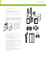
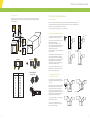
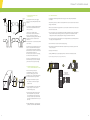
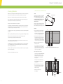
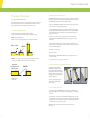
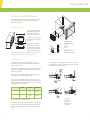
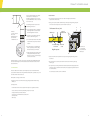
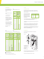
Climaver® installation manual
The pre-insulated glass mineral wool ductwork system
Saint-Gobain Isover
East Leake
Loughborough
Leicestershire LE12 6JU
Tel: +44 (0) 115 945 1050
Fax: +44 (0) 115 945 1915
www.isover.co.uk
Version 1.1
July 2008
Contents
1. Introduction to Climaver® Duct boards
Chapter 1
Introduction to Climaver® Duct boards
2
Glass wool duct boards for air conditioning ducts were first developed in the USA more than 40 years
ago. They have since been produced by CertainTeed Corporation (a Saint-Gobain company) in the USA,
and by other Saint-Gobain companies in other countries.
Chapter 2
Principles of Duct Assembly
3
Isover Spain is a glasswool and stone wool manufacturing company. It has been producing glasswool
pre-insulated duct boards since 1967 under the trade name CLIMAVER®.
Chapter 3
Creating a Straight Duct
6
CLIMAVER® glass wool duct boards are CE certified and manufactured at the Azuqueca de Henares
mineral wool factory (glass wool and stone wool). This factory has been ISO 14001 and ISO 9001
accredited.
Chapter 4
Creating Elbows and Offsets
9
Chapter 5
Creating Dynamic Branches
12
Chapter 6
Creating Reductions
15
Chapter 7
The Climaver® Metal System
17
Chapter 8
Machine Attachments and Reinforcements
19
1.1. CLIMAVER® DUCT BOARDS - CHARACTERISTICS.
Description:
CLIMAVER® is a high density glass wool duct
board and is faced either side. The outer facing,
a robust aluminium surface, acts as a vapour
barrier and maintains an air-tight seal. The inner
facing of the duct may be an aluminium facing,
an internal reinforced aluminium facing or a
woven glass cloth, which ensures an exceptional
levels of acoustic attenuation.
Uses:
Air-Conditioning, Ventilation & Heating Systems.
Duct board dimensions
Length (m)
Width (m)
Thickness (mm)
3
1.19
25
CLIMAVER® products
CLIMAVER®
Thermal
Conductivity
[λ] (W/m·K)
at 10 °C
PLUS R
0,032
Quality
markings
CE
Maximum Working Conditions
Rigidity
Class (*)
R5
Static pressure
(mm c.a.)
≤ 80
Outer lining: Aluminium foil, kraft paper, reinforced glass fibre mesh and glass veil.
Inner lining: Aluminium foil, kraft paper and glass veil.
NETO
0,032
CE
R5
≤ 80
Air speed
(m/s)
≤ 18
≤ 18
Maximum
temperature(°C)
70
70
Outer lining: Aluminium foil, kraft paper, reinforced glass fibre mesh and glass veil.
Inner lining: Woven black glass cloth ‘NETO’.
Products A2 and A2 Neto are available in the UK upon special request.
(*) In accordance with EN 13403., 2003.
1
2
Climaver® installation manual
2. Principles of Duct Assembly
2.1. LAYOUT / SKETCH
Duct Assembly:
This handbook describes the operations that
should be performed in order to ensure the
correct installation of an air distribution network
using the Climaver® System.
Definitions:
• Duct assemblies: Ductwork sections where the
air flow changes speed and/ or direction, That
is, elements that are not straight (e.g.: elbows,
reductions, branches, shoes etc.)
There are two different methods to manufacture
duct assemblies:
• Piece: Ductwork element that produces a duct
assembly when joined to other pieces
• Straight Duct Method (recommended by Isover)
• Separate module/flat piece: flat item or piece
that forms a duct assembly or straight duct
when joined to other pieces.
• Separate Module/ flat pieces method
(traditional method). In this handbook it is
only explained for the assembly of a reduction
duct fitting.
For interest, the flat pieces method creates
individual side panels for a duct which are then
cut out separately and assembled .
Regulations:
Climaver® Glass Mineral wool duct boards
conform to and are regulated by the British
Standard BS EN-13403:2003 Ventilation for
buildings- Non-metallic ducts- Ductwork made
from insulation duct boards
The focus of this handbook is the 'straight duct
method' which allows ductwork to be made
much more quickly and more efficiently. The
method allows the fabrication of a straight duct
from a single sheet, increasing the strength and
rigidity of the duct assembly.
Both of these methods will be performed using
a small number of light and easy-to-use tools.
SDM
(MTR*)
CLIMAVER® glass wool duct boards
PERFIVER L® profiles
-
Separate
Module
Method
-
CLIMAVER® glue for reinforcing the joints
of pieces when fabricating duct fittings
-
-
-
CLIMAVER® MM Square Ruler
Tangential Circular Saw
-
-
CLIMAVER® self-adhesive aluminium tape for
sealing joints externally
*(MTR denotes METODO DEL TRAMO RECTO the Spanish patented method of producing Climaver® ducts)
**See Chapter 7 for details on the Climaver® Metal System.
3
A marker pen, a measuring tape, a Climaver® knife
(double-edged flat end knife) and a Climaver® stapler
2.2. CUTTING
The following pictures show the dimensions and
cuts that should be made depending on the type
of duct that we want to obtain.
The Square Ruler (Regla Escuadra) is placed on
the duct board, and the cut is performed at the
correct dimensions by placing the appropriate
Climaver® MM tool against the ruler. This means
that the MM tool will be nearest the user at this
point. The tool's blades then enter the duct board
and the user pushes the tool away from the
initial starting position.
CLIMAVER®
METAL
SYSTEM**
PERFIVER H® profiling
CLIMAVER® MM tools
With the CLIMAVER® Square Ruler it is not necessary to mark the duct board with cutting guidelines.
The Climaver® MM tools produce cut grooves with a "chair"
shape which allow the duct boards to be folded at an angle of
90°. This produces the joints from a single piece of board.
The glasswool is removed by hand as the groove is made.
CLIMAVER®
MTR* tools
The Climaver® Square Ruler (Regla Escuadra) makes the assembly of straight ducts from a flat duct
board extremely easy as it is calibrated to allow measurement of the duct dimensions along the
bottom of the duct board.
Note: This type of cut provides more rigidity to the section.
Isover recommends this tool rather than other conventional
V-shaped cutting tools.
The tools are very light and easy to use. They save time
sketching as they are calibrated to work with the CLIMAVER®
MM Square Ruler.
Red
MM tool
Red
MM tool
Red
MM tool
Blue
MM tool
Note: CLIMAVER® MM tools are fitted with high quality
and easy-to-replace steel blades. They have been especially
developed for cutting the inner lining of CLIMAVER® duct
boards.
The following are required for manufacturing ducts:
Material
Once the cross sections and the elements of the ductwork (straight duct, elbow, offset, etc.) have
been defined, it is necessary to consider the cutting lines on the duct board dependant on the size of
the duct itself.
Black MM tool
Red MM tool
Blue MM tool
Note. CLIMAVER® tools have a plastic guide to which the blades
are set. A separate blade replacement pdf document is available
to download from Isover. Please visit www.isover.co.uk.
Chair-shape cut
2.2.1 OTHER CUTTING TOOLS
Climaver® Knife
Another cutting tool is the double bladed
Climaver® knife. The drawings below shows the
difference in the way the blade is used for cutting
duct boards into two parts and for other
operations such as cutting out edge flap.
The MTR tools shown are used to cut straight
ducts for the transformation into duct
assemblies. They can make accurate and clean
cuts because of their particular design. They are
manufactured with the proper cutting angles.
Cutting a
duct board
in two parts
Cutting out
a flap
White label tool
Yellow label tool
4
Climaver® installation manual
3. Straight Duct Fabrication - General Theory
2.2.2 OTHER ESSENTIAL ELEMENTS FOR THE STRAIGHT DUCT METHOD:
• CLIMAVER® glue, specially developed for bonding glass wool. It is an essential part of the Climaver®
system and is used for sealing joints between duct pieces fabricated using the Straight Duct Method.
• CLIMAVER® Tape. Adhesive aluminium tape for sealing external duct joints. The word “CLIMAVER®”
is printed on the tape as a reference of quality. It is also an essential part of the Climaver® system.
2.3. CLOSURE
Two closure systems can be used:
Inner closure:
A sealer must be applied to all the joints used
to make duct fittings such as elbows, branch,
trouser and dynamic branches...
Outer closure:
The external closure of ducts from the
CLIMAVER® range ensures a high level of airtightness, with virtually no air leaks, provided
that the ducts have been correctly fabricated
and assembled.
Important: In order to guarantee duct resistance
and durability, the adhesive tape used must be
Climaver® branded tape which has the following
characteristics.
• Pure aluminium tape 50 mµ thick,
with acrylic resin-based adhesive.
• The tape also has a nominal width of 65 mm.
Sealing is achieved by applying a bead of
CLIMAVER® glue to the glass mineral wool
surface of one piece, next to the edge of the inner
facing and finally to the inner seam of the
section.
It is necessary to ensure that the CLIMAVER® glue
dries completely between the contact surfaces.
External closures of the pieces forming the duct
fitting should also be completely sealed. The
pieces must be securely held together by
applying CLIMAVER® tape across the external
joints on each duct face before taping over the
inner seam.
Recommendations for applying aluminium tape:
In order to apply the Climaver® aluminium tape,
room temperature must be above 0°C. Dirt must
be removed from the surfaces to be sealed. It is
necessary to press it and rub it firmly with a
Climaver® Spatula until the facing reinforcement
can be seen clearly through the tape.
Longitudinal duct joints can also be sealed using
Climaver® aluminium tape. The tape must be
applied so that half the width is placed over the
stapled flap (see section 2.4) and the other half
over the surface with no flap. The trade name
"CLIMAVER®" appears on the entire length of the
tape as a mark of quality.
The easiest and quickest duct assemblies to
produce are straight rectangular ducts.
CLIMAVER® MM tools and CLIMAVER® MM
Square Ruler make the fabrication of these ducts
much simpler because the duct board does not
need any guidelines scribed or marked on the
duct board surface. The Climaver® MM Square
Ruler is actually used as the cutting guide as
described below.
It can be see on the following drawings
different ways to make straight ducts depending
on the size of the duct board and the duct
section required.
The layout and the cutting must be done on the
inner surface of the duct
B
A
A
B
Single piece
duct
A
B
B
-U- single piece and
flat piece duct
A
B
B
A
A
Two pieces in
-L- duct
A
B
Four pieces
duct
A
B
3.1. FABRICATION OF STRAIGHT DUCT WITH ONE SHEET OF CLIMAVER®. THE PROCESS.
A straight duct with inner dimensions "a" x 'b" needs to be made.
Every cut must start from the male shiplaped edge of the duct board and work towards to the female
shiplaped edge. This would mean that cuts are made form the left hand side of the board and cuts are
made progressively to the right.
In the drawing the dimensions are shown in millimetres. The ruler is calibrated to take into account
the size of the cut made by the MM tools. The ruler automatically reduces the dimensions by 40 mm
so that we can directly use the dimensions of the duct that we require straight from the ruler's
calibrated surface.
Red MM tool
(2)
A) The dimension 'a' is measured from the male
shiplaped edge of the duct board using the
CLIMAVER® MM Square Ruler. (1) The inner
face of the duct board should always be placed
upwards. A cut is the made with the
CLIMAVER® Red MM tool (2).
(1)
2.4. DOVETAILING OF SEPARATE ELEMENTS
As commented in the section on closure, the
dovetailing of separate elements to form
ductwork sections is achieved by placing the
surfaces of two sections of the duct at the same
level, stapling the flap of one of the sections on
top of the other (with no flap) and sealing the
joint with self-adhesive tape. The two sections
are easy to assemble because the rims of the two
separate sections are shiplap moulded; one
section is referred to as the "male" shiplap and
the other as the "female" shiplap.
Direction of
air circulation
Inner
surface
Outer duct surface
5
Red MM tool
(4)
Note Climaver® staples and Climaver® Stapler must be used.
CLIMAVER®'s range of duct boards have factory
made shiplap moulded edges thus making
assembly easier. Thanks to this the density of the
glass wool on this edge is far greater enhancing
the rigidity of the joint and improving assembly
to ensure a perfect interior finish.
B) The CLIMAVER® MM Square Ruler is used to
measure the dimension "b" of the duct inner
section (3). This dimension is taken from the
last cut of the two made by the Red MM tool.
(4) The CLIMAVER® Red MM tool is again used.
DOVETAILING
OF DUCT BOARDS
(3)
Exclusive rimmed
shiplap
6
Climaver® installation manual
C) Step 2 is repeated with the dimension "a",
taking the measurement from the last cut (5)
and then a cut is made with the CLIMAVER®
Red MM tool (6).
Red MM tool
(6)
(5)
3.2.LARGER DUCT SIZES OR FABRICATION OF A STRAIGHT DUCT IN TWO PIECES
Only 2 cuts are required this time.
Blue
Red
The Red MM tool creates the first cut and the
Blue MM tool the second. Use the same method
as described in 'Fabrication of straight duct with
one sheet of Climaver®. The process.'
B-40
A-40
x2
Knife
Dimensions in mm
D) Finally, as done previously in steps 2 and 3 the
dimension 'b' is measured from the last cut (7)
of the two made. Instead of using the Red MM
tool, we use the CLIMAVER® Blue MM tool (8)
in order to make the last 'chair-shape' cut and
the aluminium foil flap which is used for the
stapling. The Climaver® Knife can then be used
for cutting off the end of the board.
Blue MM tool
(8)
(7)
Note: The flap at the end must remain on the end of the
board as this used as an overlap.
E) The Climaver® Knife is then used to separate any loose glass mineral wool from the newly
created flap.
F) To remove the cut strips the duct board is lifted by placing one finger into the cut strip and the
waste is easily removed.
3.3 FABRICATION OF A STRAIGHT DUCT WITH A U SHAPED PIECE AND A FLAT PIECE.
Method:
The CLIMAVER® Square Ruler is used to measure the dimension "a" of the duct inner section. This
dimension is taken from the male shiplaped end of the board. The CLIMAVER® Red MM tool is used to
create the first cut. The CLIMAVER® Square Ruler is again used to measure the dimension "b" of the
duct inner section. The Red tool is used to create the second cut.
The final cut is made with the CLIMAVER® Blue MM tool using the dimension "a" again.
To complete the straight duct a single piece must be placed on top of the U shape. See diagram at the
start of Section 3.
The flat piece is obtained marking the dimension "b" with the Climaver® Square Ruler and cutting
with the Blue MM tool. On the two sides where the Blue MM tool has been applied, use the knife to
obtain the flaps in order to staple the U shape piece and the flat piece together.
Red
Note. The Red MM tool is used three times and the final cut is made with the blue MM tool.
Red
(1)
Red
(2) (3)
A-40
(4) (5)
B-40
A-40
Red
B-40
(8)
Blue
A-40
Dimensions in mm
B-40
Knife
Dimensions in mm (without square ruler)
Red
Blue
(6) (7)
A-40
40
40
G) If the full width (1.19 m) of the duct board is used then all the edges will have a pre-formed
male-female shiplap junction for attaching to other straight ducts. If not, then a male or female
shiplap joint has to be made using the tool with the round black hilt.
40
Blue
B-40
Knife
40
H) The final joint of the assembly must be made. This is done by folding the duct board. Pressure must
be added to force the duct into a slightly off square position. The final flap is pressed over the edge
of the corner joint. If this is done then when the pressure is released after stapling the straight duct
aligns itself correctly. The junctions at the corners will also be tight and strong.
I) Stapling. Join the flap to the opposing foil
facing (see photo) by using the Climaver®
Stapler and deliver the staples through the
foil overlap, separating them by a maximum
of 5cm.
5cm
7
8
Climaver® installation manual
4. Creating Elbows and Offsets
4.1. HOW TO FABRICATE ELBOWS.
The first duct assembly explained in this handbook is the elbow. The terminology “duct assembly” is used
to mean a non-straight duct or ducts which has been joined together.
An elbow is used to change the direction in an airflow network, without dividing the airflow in two.
15 cm min.
4.1.1. ELBOWS WITH ANGLES BIGGER THAT 90°.
20 cm min.
A straight duct is made as in Chapter 2. A cutting point is chosen (see the drawing below). The subsequent
cut will follow the cutting lines which are an integral part of the surface of the Climaver® board. The 22.5%
degree cut (angle beta) is made with by the White Label Tool (see Chapter 2.2.1). The cuts made at 90° to
the direction of the board are made by the Yellow Label Tool. One of the pieces made will be rotated 180° to
create the elbow.
C LLIMA
I MA VER
VE R
E
V
A
M
LI
C
R
E
V
A
M
LI
A
V
E
R
C
LI
M
A
V
E
R
E
V
V
A
A
L IM
L IM
C
C
E
R
R
The subsequent cut will follow the cutting lines which are an integral part of the surface of the Climaver®
board. The 22.5% degree cut is made with by the White Label Tool (see Chapter 2.2.1). The cuts made at 90°
to the direction of the board are made by the Yellow Label Tool.
14,1
17,7
21,2
24,7
28,3
31,8
35,4
38,9
42,4
M
A guideline from the lined outer surface of the Climaver® board is chosen from one of the duct surfaces.
The cutting line will follow this Climaver® cutting guideline.
20
25
30
35
40
45
50
55
60
Seal with Climaver
glue and tape
LI
A
Distance D (cm)
C
D
C
Separation A (cm)
C LLIMA
I MA VER
VE R
On the two adjacent surfaces, two vertical lines are marked on the outer covering.
R
R
E
V
A
M
LI
C
R
E
V
4.2. CREATING A 90° ELBOW USING THE STRAIGHT DUCT METHOD.
A straight duct is made as in Chapter 2. A cutting point is chosen (see the drawing below) which is a
minimum of 20cm from the end of the straight duct.
Rotate 180°
A
2x β°
90° Elbow
M
α>90°
LI
β°
20 cm min.
C
<135/2°
There is no male shiplap and female shiplap end
to these pieces and therefore no flap through
which the pieces can be stapled. A bead of
CLIMAVER® glue is applied all along the rims to
join the 2 pieces and to close to the inner surface
of the duct. After joining the pieces, the
Climaver® adhesive tape is applied and any
excess glue cleaned off using the Climaver®
spatula. See Chapter 2.2.2 for further adhesive
and tape information.
To create the other symetrical cut a minimum distance of 15cm is measured (dimension A) and the process
repeated in a symetrical fashion as per the previous paragraph.
Once all the lines are cut, the middle piece is rotated by 180° and the elbow is created. It is not necessary to
put deflectors. The sealing of the pieces should be done as in section 4.1.1.
Note: It is essential that one of the guidelines from the outer covering (or an imaginary parallel one), with an angle of 22.5°, is used. If the
line is not followed elbows less than 90° (closed elbows) or more than 90º (opened elbows) would be created.
Please see the layouts on the right:
9
10
Climaver® installation manual
4.3. OFFSET - DODGE
5. Creating Dynamic Branches
Offsets are necessary in order to change of direction of the duct or to avoid obstacles in its way.
The duct maintains the same size of cross-section along its length. The next drawing shows the
construction method.
5.1. DOUBLE BRANCHES.
Branches are duct assemblies that divide a single airflow into separate airflows. Double branches split
the airflow into two within the ductwork. It can change the direction of one of the circulating air flows
(single or “R” branch) or both (double or “trouser” branch).
Note that the main branch will have the biggest proportion of any airflow within it.
5.2. SIMPLE DYNAMIC BRANCH OR “R” BRANCH.
22,5º
4 5° A ngle
It is made from a straight duct and an offset duct
with dimensions “x” and “y” respectively.
A
The first step is to add the external measures of
the two airflow exits ‘A’ & ‘B’.
Subtract the measure ‘A’ (‘A’ is the overall
dimension of the finished dynamic branch) to get
the intersected size which then leads to the
calculation of the dimension ‘c’.
This measurement “c” is to be divided by 2 which
are then called ‘d’.
22,5°
20 cm min.
20 cm min.
R
E
E
V
V
A
A
M
M
LI
LI
C
C
R
R
E
E
V
V
A
A
M
M
LI
LI
B–A = c
c/ 2 = d
A
C
C
h
B
This dimension ‘d’ is then marked on the each of
the faces of the duct which will eventually be
joined. The dimension ‘d’ will intersect with the
other marked line ‘h’. ‘h’ is quite simply the point
at which the two ducts need to meet. This
intersected area needs to be cut out using the
Climaver® Knife or White Label Tool.
Rotate 180°
R
90° Elbow
h=
xy
The joints are sealed with Climaver® glue and
then Climaver® Tape is used to the overlap the
joint to increase the joint strength.
C
LI
M
A
V
E
R
5.3. DOUBLE DYNAMIC BRANCH USING
STRAIGHT DUCTS. TROUSERS.
C
LI
M
A
V
E
R
This assembly separates a single airflow into
two airflows. A common name for this assembly
is a Trouser.
A
LI
M
A
V
E
R
C
LI
M
A
V
E
R
14,1
17,7
21,2
24,7
28,3
31,8
35,4
38,9
42,4
46
49,5
53
56,6
C
20
25
30
35
40
45
50
55
60
65
70
75
80
Seal with Climaver
glue and tape
C L I MA V E R
Distance D (cm)
C L I MA V E R
Separation A (cm)
D
Elbows of the branches for this duct assembly are
built using the instructions from the previous
chapters. The two elbows can have different
sections and the sum of both sections can be
greater that the one from the main duct, but the
height of the point at which the offset begins
must be the same. See the illustration.
A
xy
B
b –a = c
c/ 2 = d
The principle of assembly is the same as that of
the Simple Dynamic Branch.
The joints are sealed with glue and then
Climaver® Tape is used to the overlap the joint
to increase the joint strength.
11
12
Climaver® installation manual
5.4. TRIPLE DYNAMIC BRANCH USING
STRAIGHT DUCTS
4 5° A ngle
The triple dynamic branch, or three-legged
trousers, is a duct assembly that divides airflow
into three.
A
It is made from a straight duct with dimension ‘z’
and also two offset ducts with dimensions “x”
and “y” respectively.
=h
h
x
z
h2
h 2=
y
5.5.1. ALTERNATIVE METHOD
The advantage of the following method is that a strong joint can be made quickly without the
use of metal.
In the same way as above, the dimension of the dynamic branch used is cut out of the side of the duct
using the Climaver® knife.
However, instead of the branch going into the recess, the flat surface of the branch sits on the outside
surface of the principal duct.
B
b –a=c
c/4 = d
The first step is to add the external
measurements of the three airflow exits ‘B’
which is ‘x’ added to ‘y’ and added to ‘z’ .
Subtract the measure ‘A’ to get the resultant size
which then leads to the calculation of the
dimension ‘c’.
This measurement “c” is to be divided by 4 which
is then called ‘d’.
1) The sides of the intersection of the dynamic branch will be trimmed back to expose approximately
50mm of foil from the external facings of all 4 sides. The dynamic branch should have a female
shiplapped end produced by cutting away half of the glass wool with a Climaver® knife.
This dimension ‘d’ is then marked on the each of
the faces of the duct which will eventually be
joined. The dimension ‘d’ will intersect with the
other marked lines ‘h’ and ‘h2’. ‘h’ and ‘h2’ are the
points at which the ducts intersect.
This intersected area needs to be cut out using
the Climaver® Knife or White Label Tool.
4) The foil from the dynamic branch will form the overlap which is placed under the peeled back foil
of the principal duct.
2) The external foil on the principal duct will also be carefully peeled back by approximately 50mm at
the entry point for the dynamic branch.
3) The black label tool is used to create male shiplapped edges.
5) Stapling is then completed.
6) Finally, CLIMAVER® tape is applied along the perimeter of the branch and the principal duct.
Note: All the cutting and trimming can be done using the Climaver® knife.
The joints are sealed with Climaver® glue and
then Climaver® tape is used to the overlap the
joint in order to increase the joint strength.
45...
5.5. DYNAMIC BRANCH FROM ONE OF ITS
4 SIDES: COMMONLY KNOWN AS A “SHOE”.
This kind of branch is generally not
recommended but it can be useful for
connections to diffusers, grilles or other
installations, and is a quick and simple method.
An alternative method is also given below.
PERFIVER H
x
x
2b
45°
22,5°
y
y
2a
2b
2a
Rotate 180º
Overlap the tape
added to fit
for further reinforcement
Rotate 180º
1) Firstly, the branch dimension required is
cut out of the side of the duct using the
Climaver® knife.
2) The profile PERFIVER H is placed on the main
duct (see Chapter 7 for more details on
Climaver® Metal Systems).
Principal
3) The branch is then added and inserted into
the main duct which creates a friction fit
connection with the Perfiver H. The branch
cannot pass into the inside of the main duct
due to the fact that the Perfiver H has a lip on
the inside.
4) Finally, CLIMAVER® tape is applied along the
perimeter of the branch and the PERFIVER H.
13
14
Climaver® installation manual
6. Creating Reductions.
6.1. REDUCTION TO ONE SIDE. U-SHAPE AND A FLAT PIECE.
Reductions are very commonly found in ductwork systems. Reductions are defined as changes in the
duct cross sectional area dimension and are used to alter the airflow direction and speed.
General
Reductions are the only kind of duct fittings that should be made by the Flat Pieces Method.
There are different kinds of reductions depending on the number of sides to be reduced (1, 2, 3 or
4 sides) and the axis of its two entrances (centred or off-centre).
Some aspects common to the fabrication of the reductions:
• The straight part of the reduction (called dimension ‘x’) must be taken into account and must be a
minimum of 10cm in size. This ensures a suitable amount of Climaver® material onto which the
principal duct leading to the final reduction can be fixed.
• It is better if the reduction is as long as possible (min 30 cm), in order to avoid sudden impacts with
the airflow.
• When it is possible, start with the flat piece, which provides a good guide for building the reduction.
• All the faces which are folded must have transversal cuts with closed angles (clefts).
Try to avoid leaving open cuts that may weaken the duct board.
• If the reduction is to impel the airflow the male side of the Climaver® board must be reduced, or
conversely, the female side must be reduced.
• In bending the flat pieces, an inner angled cut (cleft) with a dimension of ‘x’, is made and bent into
place. It should always on the side the module. Similarly another cut is made on the other edge
of the module, also with dimension ‘x’.
• Sometimes a sudden change in direction or in the duct section makes it necessary to cut segments
(bevel cuts on the duct board).
• All clefts and cuts must always be glued or taped.
To fabricate the U shape two cuts are made with
the Red MM tool at distances ‘a+ 1cm’ and ‘b+
1cm’; remember that if the Square Ruler is used
to make the cuts, then it is not necessary to add
one centimetre more because the ruler is
calibrated to do this.
Interior cleft made
Exterior cleft made
b
x
b
a
x
Two lines also have to be marked that should be
parallel to the shiplaped ends at distance ‘x’ on
both sides (this may be the same distance or not).
c
Fabrication
1) First of all, cut the panel twice with the Red
MM tool with the dimensions ‘a+1cm’ and
then ‘b+1cm’. This is measured with the square
rule, as if creating a regular straight duct.
a +1
b+ 1
a +1
b+ 1
x
2) To the left hand side of the first cut, a line is
traced called at a distance of ‘c+1 cm’. Note. ‘c’
is the dimension or height at the end of the
reduction. Another line is traced of dimension
‘c+2 cm’ on the opposite side of the second cut.
3) After the second cut another line is traced
of dimension ‘a+2 cm’.
Note, the reason that the lines are traced is due to the fact
that the point at which the top piece is to be folded has to
be also measured and traced across the length of the board.
(dimension ‘x’). The coincidence of these lines creates the
reduction effect as per the 3rd illustration.
x
The cuts are made with the Red MM tool
The square ruler is automatically calibrated with the extra 1cm required
4) The reduction’s lid can now be cut.
Cut the last piece using the Blue MM tool with
dimension ‘b’ as shown. There is no exact
starting point for this cut as it just needs to
be to the side of the ‘U- shape’ template
already cut out.
The blue tool is used as it creates the foil
flaps through which the 2 pieces can be
stapled together.
Blue MM tool
a+1
b+1
5) An internal cut is realised on one side and
an external one on the other. This lid will be
shorter than the other three: just cut off
what is not necessary.
1
2
6) Finally, staple and tape the two
pieces together.
c+1
c+1
a+2
b
3
4
c+2
b
x
x
Red MM tool
15
16
Climaver® installation manual
7. The Climaver® Metal System®
7 2. ADVANTAGES OF THE CLIMAVER® METAL® SYSTEM
This is an option to the standard Climaver® System.
CLIMAVER® METAL SYSTEM ducts have been developed to aid mechanical properties by strengthening
the system and to make for easier maintenance of the ductwork. Many tests have been performed on
the CLIMAVER® METAL SYSTEM. They have shown the following advantages:
The most demanding requirements for indoor air quality and intensive cleaning can be achieved with
Climaver® Metal System. Climaver® Metal is a top quality alternative and combines the Climaver®
duct boards with the aluminium profiles called Perfiver L and Perfiver H. See below:
7.1. COMPONENTS OF CLIMAVER® METAL SYSTEM
• Climaver® Metal System can be assembled with any Climaver® duct board.
See Chapter 1 for the table which indicates the full range of components for this system.
• Certification of CLIMAVER® METAL SYSTEM ducts by the most prestigious duct cleaning associations,
and in accordance with international standardised methods.
• Durability. CLIMAVER® METAL SYSTEM ducts have successfully gone through accelerated multiplecycle ageing tests with temperature and humidity variations. One of these tests is the FLORIDA TEST
(21 cycles with a duration of 8 hours and with variations in relative humidity and temperature of
18% to 98% and 25°C to 55°C).
• PERFIVER®: patented aluminium profiles.
PERFIVER L: it is used in internal longitudinal duct joints, to strengthen and protect them.
• Greater mechanical resistance to pressure. Tests performed in accordance with the European
Standard EN 13403 enable CLIMAVER® METAL SYSTEM ducts to achieve static pressures of 800
Pa (80 mm. c. a.)
Duct cross section
• Mould proliferation prevention test. Climaver® ducts do not facilitate the development of microorganisms or moulds, as shown by the tests performed in an independent laboratory and carried out
in accordance with European EN-13403
PERFIVER L
• Air circulation speeds of up to 18m/s.
• High acoustic absorption.
• Maximum air-tightness. CLIMAVER® METAL SYSTEM ducts present the lowest levels of pressure
losses due to air-leakage.
• PERFIVER H: it is used to protect the edges of glass wool ducts in grids, machinery connections,
and inspection doors. PERFIVER H is not exclusive to the Climaver® Metal System.
Duct section:
inspection doors and
grid connections
• CLIMAVER® Adhesive.
• CLIMAVER® Tape.
Note. The European EN-13403 has the status of the British Standard BS EN 13403: 2003.
7.3. HOW TO FIT PERFIVER L IN DUCTS WITH THE CLIMAVER® METAL SYSTEM
PERFIVER H
The fabrication of a straight duct with
CLIMAVER® METAL SYSTEM is based on the
previous method, common to all CLIMAVER®
ducts, but with the main difference such that one
PERFIVER L profile (1.155 long) is placed on each
chair-shape cut. These cuts run along the inner
length of the straight duct.
The creates a reinforcement along the duct
joint which could be damaged through
extensive cleaning.
7.4 CUTTING OF CLIMAVER® METAL PROFILES
• If an installation is built with CLIMAVER® METAL, then the ducts will carry the PERFIVER L profiles
throughout their length. The easiest and fastest way to cut aluminium profiles is to use a Tangential
Circular Saw.
• The diameter for the saw disc should be around 130 mm with approximately 80 teeth. The Circular
Saw cut shouldn’t be less than 38 mm deep and not more than 40 mm (Circular Saws normally have
an adjustment device). The Circular Saw will also have a device for setting the cutting angle. Cuts will
be usually made at 90°, 67.5° and 45° to the duct surface.
IMPORTANT: For safety and cleanliness at work, a vacuum system must be connected to
the Circular Saw.
17
18
Climaver® installation manual
8. Machine Attachments and Reinforcements
3
This chapter will focus on different auxiliary operations to be performed in a Climaver® duct in order
to complete the installation; for example, connections to machinery, connections to grilles or
diffusers, supports and reinforcements.
8.1. FABRICATION OF AN ACCESS HATCH.
Regulations governing Thermal Installations in
Buildings stipulate the requirement to fabricate
thermally efficient access hatches in ducts to
enable the inspection of duct installations.
PERFIVER H
In order to fabricate an access hatch, we have to
cut a window of the chosen dimensions with the
Climaver® knife.
DUCT BOARD
CLIMAVER PLUS R
x
y
FRAME DIMENSION
PERFIVER H
PERFIVER H
A frame must be placed in this window; this
frame is made using the profile PERFIVER H. In
order to cut the profiles and shape the frame for
the inspection cover, the recess must be cut at a
straight angle and then the profile section is cut.
Note: Climaver® can be adapted to fit standard access hatches. The profile PERFIVER H is not used exclusively in the Climaver®
Metal System. It can also be used to fabricate connections to machines for all types of Climaver® ducts.
4
1
5
7
6
1
7
4
1. CLIMAVER® Range Duct
2. CLIMAVER® Aluminium Tape
3. Deflector
4. Metal frame
5. Hatch
6. Grille
7. Rectangular CLIMAVER® collar
8. PERFIVER profile connection frame
8
5
6
2
Cross-section
8.2. CONNECTION TO A GRILLE.
8.3. CONNECTION TO A MACHINE
Connecting ducts to grilles is a common operation of the installers’ work. In order to make a
connection from a duct, a frame is made using the profile PERFIVER H as described previously, and
with the same dimensions as the grille.
The outlet connecting the air conditioning equipment to the ducts is one of the most critical points
in the installation due to it’s air speed, which is at it’s maximum at this point, and also due to the fact
that normally there is little free space available at this stage.
A straight duct has also to be made with the same length as the distance between the false ceiling (in
which the grille has been fitted) and the air conditioning duct (which it will be connected to). The
maximum distance should be 20cm.
4
3
1
2
In order to make the connection, the straight section from the duct frame to the grille is made and
joined with Climaver® tape. This ensures that the straight duct is airtight.
5
3
A similar process is used for connecting diffusers, but in this case the duct must be connected to a
plenum (this plenum has to be placed before the outlet of the diffuser). This connection will be made
in this way: the angle between the duct and the diffuser air outlet has to be 90°, so the kinetic energy
of the fluid will turn into static pressure in the plenum.
4
4
Installation
Duct direction
Objective of the duct
GRILLE
Directly
Parallel to the
air outlet
Maximise
Kinetic Energy
DIFFUSER
Through the Plenum
Perpendicular to the
air outlet
Maximise
Static Pressure
The process is similar if a pipe is used for making the connection.
In this case, we make a circular cut on the main duct, with similar dimension to the coupling to attach.
Then we place a ring or support bar on it in which the crown coupling will be installed. We place the
flexi duct on top of this coupling. The other end of the coupling is connected to the diffuser or grille
by a clamp.
19
3
2
1
1
3
2
1. Equipment clamp
2. Sheet metal screw
3. CLIMAVER® Duct
4. PERFIVER H profile joint
5. Sheet metal angle
20
Climaver® installation manual
There are different methods for connecting the
main duct to the air conditioning unit.
Nevertheless, it will always be necessary to use
the profile PERFIVER H and screws to ensure that
the connection is safe.
The following instructions must be observed
when making the connection:
r
a
Dimensions
a = from 1.5* b to 2.5* b
where b is the
maximum dimension
of the fan mouth
r = minimum of 15 cm
1) The fan outlet must remain in a straight duct
with a length between 1.5 and 2.5 times the
maximum length of the fan entrance.
Fabrication Method
1) The exterior measurements of each duct side are taken and length of U profile will be the
equivalent of the sum of the sides.
2) The legs of the U profile should be cut with tin snips to allow easy bending. In this way, the profile
can be bent in order to adapt it to the exterior circumference of the duct.
1
Reinforcement for cross joints
Adhesive tape
U-shaped
reinforcement
2
3
2) If reductions are made after the outlet, they
must have a maximum angle of 15°.
b
3) If an elbow is built, the direction of the airflow
in the elbow must correspond to the direction
of the fan.
4) The connection to the air conditioning unit
must be adjusted using a flexible coupling;
this will prevent the spread of vibrations.
5) Finally, and depending on the relative position
of the equipment clamp and the air duct, it
may be necessary to place a sheet metal angle
to reinforce the connection.
Duct inner
Sheet metal cutting
50 x 150 mm
Sheet metal
screws
1. Climaver® duct
2. U-shaped profile
3. Sheet metal screws
4. Metal plate
Negative pressure
4
3) Holes are then drilled on the profile. The holes are spaced at enough long intervals to guarantee
no deflection.
The different layouts use a screw to ensure the connection between the profile PERFIVER H and the
duct board. Another thing to bear in mind is that the duct board must not be introduced in the air
outlet of the machine.
4) The sheet metal pieces are held in place on the internal surface of the Climaver® system using
Climaver® glue.
8.4. REINFORCEMENTS
5) The cut profile is placed on the joint between the duct boards (male-female shiplap joint). Then the
sheet metal screws are introduced into the holes of the profile, passing through the duct board and
the sheet metal offcuts.
The distance between reinforcements is determined by the duct section and maximum air flow
pressure, with the intention of not reaching maximum deflection, which is equivalent to one percent
of the measurement of the side of the duct.
The sheet metal pieces shall be 0.8 mm or 1.2 mm thick.
Normally there are two types of reinforcement:
1) rods, which use we do not recommend because they go through the duct and make cleaning
difficult; and
2) U-shaped profiles.
The fabrication of reinforcements is explained in this chapter here using this latter method.
In order to fabricate a reinforcement, the following components are needed:
U-shaped profile to wrap around the entire duct
sheet metal pieces of minimum dimensions 50x150 mm
sheet metal screws
adhesive tape.
21
22
Climaver® installation manual
8.5 REINFORCEMENT TABLES
8.5. SUPPORTS.
Tables I, II and III indicate the types of
reinforcement and the distance between each
reinforcement, based on the following
parameters:
• Maximum interior dimensions of the duct
in mm.
• For a maximum deflection of L/100
(distance between supports).
Table I
Outer Reinforcements (max. pressure: 150 Pa)
Duct board stiffness
Inner
dimensions
Maximum (mm)
• Maximum work pressure of the duct in
Pa (only pressures up to 500 Pa have been
considered, although CLIMAVER® PLUS R and
CLIMAVER® METAL SYSTEM can handle
pressures up to 800 Pa).
• Climaver® Plus R boards have R5 rigidity, to
BS EN 13403:2003 (European Standard for
non-metallic ducts). This rigidity is the
maximum level established by this standard.
Please consult Isover for alternative
reinforcements.
Table II
Outer Reinforcements (max. pressure: 250 Pa)
Maximum (mm)
CLIMAVER® PLUS R
AND CLIMAVER®
METAL SYSTEM
Distance (m)
0.6
1.2
Distance (m)
0.6
1.2
≤ 375
•
•
376 - 450
•
•
451 - 450
•
•
601 - 750
•
•
751 - 900
•
•
901 - 1,050
•
•
1,051 - 1,200
>
(0.8) 25
1,201 - 1,500
>
(0.8) 25
1,501 - 1,800
>
(1.2) 25
1,801 - 2,100
>
(1.2) 30
2,101 - 2,400
>
(1.2) 40
Table III
Outer Reinforcements (max. pressure: 500 Pa)
Duct board stiffness
Inner
dimensions
CLIMAVER® PLUS R
AND CLIMAVER®
METAL SYSTEM
Duct board stiffness
Inner
dimensions
Maximum (mm)
CLIMAVER® PLUS R
AND CLIMAVER®
METAL SYSTEM
Distance (m)
0.4
The final installation of ducts on the ceiling is made using supports. The distance between the
supports is stipulated in the UNE 100-105 standard and calculated according to the section of duct
indicated in the following table.
It must also be remembered that only two
transversal joints may be placed between
supports. When the duct rim is less than
2m in length and has no reinforcements,
a maximum of two transversal joints may
exist between supports.
≤ 375
•
•
≤ 375
•
•
•
•
376 - 450
•
•
451 - 450
•
•
451 - 450
•
•
601 - 750
•
•
601 - 750
>
(0.8) 25
751 - 900
•
•
751 - 900
>
(0.8) 25
901 - 1,050
>
(0.8) 25
901 - 1,050
>
(0.8) 25
1,051 - 1,200
>
(0.8) 30
1,051 - 1,200
>
(0.8) 25
1,201 - 1,500
(0.8) 25
1,201 - 1,500
>
(0.8) 30
1,501 - 1,800
(1.2) 25
1,501 - 1,800
>
(1.2) 30
1,801 - 2,100
(1.2) 25
1,801 - 2,100
>
(1.2) 40
2,101 - 2,400
(1.2) 30
2,101 - 2,400
>
(1.2) 50
Inner distance (mm)
Maximum distance (m)
< 900
2.4
900 to 1,500
1.8
> 1,500
1.2
- The most common method of supporting ducts is by using horizontal “U-shaped” profiles
of 25 x 50 x 25mm and made from galvanised 0.8 mm-thick sheet metal.
- This U-shaped profile is held to the ceiling by two threaded rods of at least 6mm in diameter or bars
of 25mm x 8mm.
- When the duct is reinforced, it is convenient that the support coincides with the reinforcement,
provided that the maximum distance stipulated in the previous table is not exceeded. In this case,
two bars and screws to the reinforcement frame would join the vertical support elements.
It is worth noting that in the case of the new CLIMAVER® Metal System there is hardly any increase in
duct weight after incorporating the profiles (400 grams). Therefore the supports do not need to be
modified in order to install the CLIMAVER® Metal System.
8.5.2. VERTICAL SUPPORTS.
The vertical supports will be placed at a maximum distance of 3m as stipulated in the
UNE 100-105 standard.
Cross-section
1
2
3
2
4
0.6
376 - 450
• The duct does not require reinforcement.
The duct cannot have reinforcements at this distance.
> The duct may have the corresponding reinforcement at the greater distance.
8.5.1. HORIZONTAL DUCT SUPPORTS.
1
1. L-shaped profile support bracket
2. Clamp for built vertical
installation by L-shaped profile
3. Sheet metal screw
4. 40 mm washer
5. Climaver® glass wool duct
5
5
When a vertical wall supports the duct, the anchoring must coincide with the reinforcement. In this
case, a sheet metal coupling must be attached to the reinforcement.
The support is made using an angle support of at least 30 x 30 x 3 (mm).
The thickness of the metal sheet and the height of the reinforcements are shown in brackets.
23
24
Climaver® installation manual
8.6. MEASUREMENT OF CLIMAVER® DUCTS.
In order to calculate the square metres of any CLIMAVER® duct from the Range installed in a ductwork
using the inner sections of each element or section that form the aforementioned ductwork, normally
the “Standards for Measuring Insulating Ducts” of ANDIMA (National Association of Insulating
Materials Industries) are applied.
These regulations are also applied to the calculation of preliminary measurements starting from the
air distribution plane that belongs to the air conditioning, heating or ventilation installations and
knowing the thickness of the material (in case of CLIMAVER® ducts, this is 0.025m).
The following diagrams show the different elements with their area formulae in metres. (The duct
fittings corresponding to the three-piece 90° elbows and the “trouser” formed by the union of two
elements as described before does not belong to the ANDIMA standards. They are included in this
manual as a guide for calculation purposes).
L
L
a
a
b
b
Straight Duct
S = 2 · (a + b + 0.2) · L
Duct Reduction
S = 2 · (a + b + 0.2) · L
b2
a
a2
L1
b3
b1
Three-piece elbow
S = 3,2 · (a + b + 0,2) · L
25
L3
a3
b
L
L2
a1
Straight trouser
S = 2 · (a1 + b1 + 0,2) · (L1 +L2 + L3)
where (a1 + b1) > (a2 + b2) y (a1 + b1) > (a3 + b3)
26