1
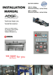
INSTALLATION
MANUAL
Technical Help Line
Tel 08700 434512
Sales Line: 08700 434512
Fax Number: 08700 434524
Email: [email protected]
Website: www.adsf.co.uk
:
ADSF 1000
Ertain Model
Total Door Weight 160 Kg
ADSF 1000 Operator
WEOPEN FORYOU
THEDOORS
ADSF 1000 INTRODUCTION
ADSF 1000 ERREKA Automatic Doors would like to thank you for placing your trust in us and for choosing one of our
products. Please read this installation manual carefully to ensure that the door is correctly installed.
ADSF 1000 ERREKA Automatic Doors in not liable for any possible damage caused by not following the instructions in
this installation manual.
ADSF 1000 Operator
CHECK Nº
Rev00
Date
01/07/10
ADSF 1000 INDEX
1.
KEY TOOLS ............................................................................................................................................................. 2
2.
ELECTRICAL EQUIPMENT..................................................................................................................................... 3
3.
TECHNICAL FEATURES......................................................................................................................................... 3
4.
ASSEMBLY .............................................................................................................................................................. 4
5.
ELECTRONIC OPERATION PANEL ..................................................................................................................... 14
6.
START (Set Up) ..................................................................................................................................................... 21
7.
PARAMETER SETTING WITH THE SELECTOR ................................................................................................. 23
8.
FAULT FINDING GUIDE........................................................................................................................................ 27
9.
ANNEXES .............................................................................................................................................................. 28
___________________
ADSF 1000 Information
In general, all door leafs would normally
be manufactured at a height from floor level
to the underside of transom + 10mm
Door Leaf
In cases where a threshold is fitted, then
measurement would be taken from top of
threshold to underside of transom + 10mm
1
WARNINGS FOR THE FITTER–SAFETY INSTRUCTIONS
The importance of this manual ADSF 1000 Operator
- Before beginning the installation read this manual duly and follow its instructions. Faliure to follow the instructions
could result in accidents and faults.
-
Erreka Automatic Doors is not liable for any possible damage caused by not following the instructions in this
installation manual.
Intended use
- This operator has been designed to be installed as part of an automatic sliding door system for pedestrians
- Any installation for use different to that indicated is considered inappropriate and dangerous.
Safety Elements
- This operator compiles with all current safety regulations. Follow the instructions for all of the elements used in the
installation.
- ADSF Automatic Doors will not accept responsibility for any safety problems or door malfunctions if components not
made by ADSF Erreka are used in the installation.
1. KEY TOOLS
7 DRILL BIT
FLAT SCREWDRIVER
8.5 DRILL BIT
Nº10 SPANNER
M8 BOLT
Nº13 SPANNER
DRIL
WIRE STRIPPER
CROSSHEAD SCREWDRIVER
Nº4 T-HANDLE ALLEN
WRENCH
Nº 13 SOCKET
WRENCH
CLAMP
Technical Help Line for the ADSF 1000 Operator
Tel 08700 434512
www.adsf.co.uk
2
SPIRIT
LEVEL
2. ELECTRICAL EQUIPMENT
ADSF 1000 Operator
P
ic
on
ctr
Ele
er
ow
ly
pp
Su
ard
bo
ADSF 1000 Operator
Nº
DESCRIPTION
CABLES
1
Power supply
4 wire hose
2
Selector
5 wires shielded
3
485 centralised connection line
2 wire
4
Security key
2 wire
5
Radars
4+4 wires
6
Photocells
2+2 wires
3. TECHNICAL FEATURES
CARACTERISTICS
ADSF 1000 Operator
Operator 1450
Operator 1850
Free passage (2 sliding leaves)
1000-2300mm
1100-3000mm
Free passage (1 sliding leaf)
750-1150mm
1000-1550mm
80 + 80 Kg.
80 + 80 Kg.
120 Kg.
120 Kg.
Max leaf weight (2 leaves)
Max leaf weight (1 leaf)
Max opening speed
0.7 m/s
0.7 m/s
Min opening speed
0.4 m/s
0.4 m/s
Max closing speed
0.5 m/s
0.5 m/s
Min closing speed
0.2 m/s
0.2 m/s
Max closing force
150 N
150 N
-20ºC/ +50ºC
-20ºC/ +50ºC
Temperature
Open door timing
Power suplply (single phase)
Consumption
Battery
90 seg.
90 seg.
220/110 V (single phase)
220/110 V (single phase)
100 W
100 W
Lead ( 12+12 v)
Lead ( 12+12 v)
3
4. ASSEMBLY
ADSF 1000 Operator
This section explains in detail how to assemble the installation. For your information, we have included below a diagram
of the Profiles and the external dimensions of the driving unit.
1
3
2
1.- Case Profile.
1.- Perfil Caja.
2.2.-Cover
PerfilProfile.
Tapa.
3.rubber.
3.-Anti-vibration
Goma antivibración.
15
35
135
165
60
ADSF 1000 Operator
4
4.1 Structure measurements before installation
ADSF 1000 Operator
ADSF 1000 Operator
B
Measure the dimensions where the door will be installed;
- Clear height (H)
- Total widht (B)
- Define the Free passage widht (PL), Clear height (H), the fixed leaf width
H
(FW) and the length of the case profile (B).
B=2xPL+2xSC +100
FW
PL
SC
4.2 Fitting the case profile
There are differents manners of fitting;
FW
SC
ADSF 1000 Operator
ADSF 1000 Operator
1.- Wall / UPN
65
Steps;
165
1.- The base of the Case profile it has to be at
95
73
135
160
35mm from the base of the Self supporting beam.
35
2.- Drill holes in the Case profile.
max. 3m
ADSF 1000 Operator
2.- Erreka - Self supporting Beam 1
20
60
95
73
135
160
165
35
3.- With the Case profile in the correct position, drill
holes in the Self supporting beam.
4.- Fix the case profiles to the Self supporting beam.
2.- Erreka – Self supporting Beam 2
ADSF 1000 Operator
5.- Verify that the Case profile is in the correct
position.
60
35
95
73
135
160
165
5
4.3 Positon the carriers on the roller track
- With the nº 4 Allen key loosen the wheel of the middle (anti-derailing
ADSF 1000 Operator
Anti-derailing wheel
Ertain Carrier
wheel) and move to the downster position.
- Hang the carrier assembly on the track.
- Fit the anti-derailing wheel in the upper position.
Anti-derailing wheel
4.4 Fitting the fixed leaves
ADSF 1000 Operator
- Mount the leaves following the instructions provided in the profile
installation manual.
4.5 Fix the hanger bar to the leaves
ADSF 1000 Operator
- Mount the hanger bars on the sliding leaves as indicated in the
diagram. The hanger bar centre should be approx 170mm from the
sliding leaf side.
- Attach the M8x25 screws with wrench nº 13, 2 per hanger.
- For other profiles drill the holes at each and following the
measurements below:
124
92
170
92
124
170
4.6 Hang the leaves on the carrier assemblies
- Fasten the hangar bars to the carrier assemblies using M6x16
Allen screws with toothed and flat washers.
6
ADSF 1000 Operator
4.7 Depth adjustment of the sliding leaves
ADSF 1000 Operator
- Use wrench nº13 to position the sliding leaf parallel to the case
profile. Then measure the distances between the leaf and the Self
supporting beam.
15.5
27
4.8 Fitting the guide
ADSF 1000 Operator
- Move the sliding leaf until it is at a 90º angle. Use a spirit level for this.
- Then position the guide on the floor at the end of the fixed leaf, with
the block in the sliding leaf guide, make a mark on the floor when the
leaf is level.
- Then fix the guide to the floor and slide the leaf along the guide.
90
4.9 Setting the height of the sliding leaves
°
ADSF 1000 Operator
- Adjust the leaf height with the centre bolt. This adjustment is import in order to obtain a
perfect fit between the two sliding leaves when they come together.
Regulation screw
4.10 Fitting the limit switches
ADSF 1000 Operator
- Place a limit switch at the point where the sliding leaves meet. To do this insert the long nuts in the slide and fasten the
limit switch unit using M6x10 Allen screws.
- The other limit switch will be mounted on one of the sides.
Limit switch
Tope lateral
7
4.11 Wiring preparation
ADSF 1000 Operator
- It is VERY IMPORTANT to wire the peripherals (photocell, radars, selector,
) before fitting the door operator. If not, it
is difficult to fit the cable conduit. You must pass the wires to where the control board will be to enable their connection
to the control board later on. To fix cables use the supplied cable conduit which is position as in the diagram below.
Posicionado
Position wires
del cableado
ADSF 1000 Operator
For taking away used the screwdriver!!!
Wires
8
4.12 Mount the arms to the slides
ADSF 1000 Operator
2 sliding leaves
- Secure the dividers with a nº10 wrench inserting the M6x20 bolts from the rear with
Right inner carrier
teethed washers.
- The arms Hill be positioned as follows; the right arm in the upper position (right
inner carrier assembly) and the left arm in the lower position (left inner carrier
assembly).
Left inner carrier
ADSF 1000 Operator
1 sliding leaf
- Opening to the right
Fix the arm onto the upper right slide.
-
ADSF 1000 Operator
Opening to the left
Fix the arm onto the upper left slide.
ADSF 1000 Operator
9
4.13 Securing the brackets to the belt
ADSF 1000 Operator
- Insert the brackets (1) y (3) in the belt the same number of teeth away as each of the pulleys.
- Fit the covers (2) and (4) to the brackets and fix them with 2 countersunk screws and M6 nuts.
- Move the brackets toward the drive centre by pulling the belt.
ATENTION: In the case of one sliding leaf fit just one bracket.
ADSF 1000 Operator
2
4
3
1
4.14 Position and secure the drive profile
ADSF 1000 Operator
-Loosen the 4 M6x16 bolts until they are at a level with the long nut, and leave them on the track as indicated in the
diagram.
- Open the doors before fitting the motor unit, so that the arms do not obstruct the mechanism.
- Take the motor unit and move it upwards until it reaches its limit against the case section.
- Move the motor unit inwards, so that the tabs fit into place. The unit can then be released.
- Place the motor unit laterally, according to the type of installation.
Insert the M6x16 Allen bolt until it reaches the case section, and turn the bolt until the motor unit is firmly fixed to the
case section.
10
Fitting the drive to the case section:
Lift the profile up until
it comes to a stop
ADSF 1000 Operator
Move towards the case profile
Position drive unit in the case profile
Turn clockwise
Push the screw
upwards
ADSF 1000 Operator
- 2 sliding leaves: IN THE CENTRE
- 1 right opening sliding leaf: ON THE LEFT
100:200
- 1 left opening sliding leaf: ON THE RIGHT
100:200
4.15 Fasten the brackets to the arms
ADSF 1000 Operator
-Slightly loosen the M6x12 countersunk bolts holding the brackets in
place, and move one of the sliding leaves. Insert the M6 nuts to fasten
the bracket inside the arm rail, then tighten the M6 countersunk bolts
using the nº 4 Allen wrench.
Slightly
loosen
-Move the 2 sliding leaves until they make contact, then fasten the
other bracket to the other arm.
-Perform the same operation and manually check that the leaves can
move to the limit switch
11
Tighten
4.16 Fitting the rubber and the side covers
ADSF 1000 Operator
- Fit the rubber (the entire length) in the case profile.
- Mount the side covers attaching them to the case profile with
4,2x13 countersunk
sheet metal screws.
Rubber
4.17 Fitting the cover supports
ADSF 1000 Operator
- Place the long screws in the direction of the case profile track, move the screw until it stop against the case profile.
When it can not go any further, turn the
4 T-handle Allen wrench clockwise.
- Place the two cover supports in the positions indicated;
4.18 Fitting the cover Profile
ADSF 1000 Operator
- Drill two 6.5mm diameter holes in the two ends of the cover section.
- The distance from the centre of the hole to the end should be
12mm.
- Fixed the “Paracaida” o the Case profile and Cover profile. Fixed it
in the two ends of the cover section.
- When the section is positioned, allow it to slide down by its own
weight until the cover pivots. Lastly, fix the cover section to the side
covers using two M6x15 bolts (one at each end).
Important; the cover does not need to be completely detached from
the unit for maintenance: it can be partially detached and left
hanging.
12
4.19 Fitting the Electric-lock
ADSF 1000 Operator
2 Sliding leaves ADSF 1000 Operator
Electric lock
Manual Unlocking System
Electric lock
1 Sliding leaf
Manual Unlocking System
ADSF 1000 Operator
Electric lock
Manual Unlocking System
Electric lock
Manual Unlocking System
- Fix the carrier blocking (2) to the Carrier (3) with two bolts.
- With the door open, insert 2 specials nuts in the middle of the Case profile (3). (See the picture)
- Fix the “Electric-Lock” (9) with two bolts. Move the wings to the closed position by hand. Adjust the position of the
Electric-lock.
- Place the support (4) of the unlocking cable at some 60mm to the left (or right) of the Electric – Lock.
- Place the handle (5) in the left (or right) corner of the Case profile.
- Put the Cover cable (7) from the support (4) to the handle (6).
- Fed the Cable (8) through the hole of the part linked to the rear axle of the electromagnet. Bear in mind that the brass flange (10) and
the spring (11) must be passed first before passing them through the support of the cover.
- With the handle in the down position, the Electric-lock in the upper position an d the cable tensioning, fix the cable to the handle by
tightening the pin of the handle. Cut the cable at the height of the handle.
- Connect the cables to the Electronic operation panel.
Inside Manual Unlocking system
7
4
11
Inside and outside Manual Unlocking system
3
10
External manual
Unlocking
8
6
5
1
9
2
13
5. ELECTRONIC OPERATION PANEL
5.1 Connection terminals
ADSF 1000 Operator
Normally closed inputs: Photocells terminals 2 and 5; Safety sensor; terminals 6 and 8; external key; terminals 9
and 12.
Terminal 1 of the supply input is transistorised. Supply is interrupted in “Door Closed” mode or with the external
key signal, terminal 9, open.
5.2 Diagram of control panel
ADSF 1000 Operator
J6
J3
J1
F1
J4
F2
J5
J2
14
ADSF 1000 Operator
LED DIODES
ON
OF
VAC
220V mains voltage
No mains voltage
ENC1
Encoder track 1 signal
ENC2
Encoder track 2 signal
+5V
Voltage to Microprocessor
No voltage to microprocessor
INSIDE RADAR
Internal radar input closed
Internal radar input open
OUTSIDE RADAR
External radar input closed
External radar input open
PHOTOCELL(NC)
Photocell input closed
Photocell input open
SAFETY SENSOR(NC)
Safety sensor closed
Safety sensor open
EXTERNAL KEY(NC)
External key input closed
External key input open
EMERGENCY
Emergency input closed
External key input open
RESET
Performing reset operation
ADSF 1000 Operator
CONNECTORS
MEANING
J1
Peripheral input terminal strip
J2
Connector for input of communication unit (485)
J3
Connector of geared motor+encoder
J4
Connector for input of supply (net + batteries)
J5
Connector for electro-lock input
J6
Plug-in connector for receiver of remote control
ADSF 1000 Operator
FUSES
FUNCTION
F1
Fuse 5x20 8 A (motor protection)
F2
Fuse 5x20 5 A (battery protection)
F3
(Fuse power supply input)
For 220V fuse 5x20 2A
For 110V fuse 5x20 4A
15
16
Emergency
External Key
+
-
12- Common (GND)
10- Emergency
12- Common (GND)
9- External key
8- Safety Sensor (Signal) NO
7- +12v (Power)
6- Common (Power)
6- Common (Signal)
7- +12v (Power)
6- Common (Power)
NC
6- Common (Signal)
(com)
SAFETY
SENSOR
Power
4- Outside Radar (signal) NO
2- Common (signal)
5- Photocell (Signal)
Amplifier Photocells
OUTSIDE
RADAR
Power
2- Common (power)
1- +12v
Selector
INSIDE
RADAR
+12 Tx CLK Rx Com
Power
12- Common (GND)
13- Rx-Selector
14- Clk-Selector
15- Tx-Selector
16- +12v
1- +12v
2- Common (Power)
2- Common (Signal)
3- Inside Radar (Signal) NO
Power
+24VDC
GND
RADAR +
PHOTOCELLS
ADSF 1000 Operator ERTAIN SYSTEM
Electro-Lock
1- +12v
2- Common (Power)
2- Common (Signal)
Inside Radar / Outside (Signal) NO
6- Common (Signal)
5- Photocell (Signal)
5.3 Standar connection
ADSF 1000 Operator
Photocells ADSF 1000 Operator
1 2
COM
3 4
5
6 7
PHOTOCELL AMPLIFIER
8 9 10 11 12 13 14 15 16
type of door frame. If 1 photocell is installed, place it at 500 mm from the floor. If 2
3 4
- Install the photocell transmitter/receiver in its corresponding position according to the
GND
12-24V
NO
NC
5
tape on the case section.
1 2
Place the amplifier on the motor unit or case section, and fix it in place with the adhesive
photocells are installed, place one of them at 1000 mm from the floor and the other at
200 mm.
- Thread the transmitter and receiver cables
Amplifier
through the cable conduit to the photocell
amplifier, and make the connections as shown
in diagram 1.
- Connect the amplifier to the panel with the 4-wire cable as shown in Diagram 2.
Connection to the mains ADSF 1000 Operator
- Thread the cable through the cable conduit, then clip it to the case section and run it to the power supply unit. To do
this, strip the cables and fix the connector to one end. Finally, insert the connector into its base,
located in the power supply unit.
Radars ADSF 1000 Operator
- Connect the internal radar directly to the panel. Run the external radar cable to the left side of the motor unit through
the standard U-section. Make a hole through the case profile and thread the cables through the cable conduit to the
panel.
- For the wiring connections, see Diagram 3.
1 2
3 4
3 4
5
5
2
5
8 9 10 11 12 13 14 15 16
3 4
Diagram 3
6 7
1 2
12-24V
GND
COM
NO
NC
1 2
12-24V
GND
COM
NO
NC
1.-Internal
Radarradar
Interior
1.2.External
radar
2.- Radar Exterior
Electrical locking device ADSF 1000 Operator
17
1
Digital Selector ADSF 1000 Operator
1 2
3 4
- The selector is the user-control panel communication device for controlling and
performing the following functions:
5
6 7
2.-Setting the operating parameters.
SELECTOR
3.-Switching the options on and off.
4.-Diagnosing failures and error modes.
- While the door is functioning, the working mode it is functioning in will appear on the
display.
GND
Rx
CLK
Tx
24v DC
Diagram 4
ADSF UK LTD
5.4 Auxiliary connections
ADSF 1000 Operator
External key ADSF 1000 Operator
- The external key is a safety switch operated from outside. The input is NC.
It has two positions:
External
key
Llave
exterior
A: disabled (contact closed)
C: enabled (contact open)
- When the lock is in position C, the door is in "locked" position and the
9- External key (sin polaridad)
blocking function is activated (if incorporated).
12- Common (GND)
- In position A, the door returns to the last function it was in before the lock
was enabled. However, if it was in "Door closed" position, it will always open
once, to enable the person activating the lock to enter.
Pedestrians may exit through the door if the key is activated by pressing “SSA” on the selector, or button “1”. When either of these buttons these are
pressed, the door will remain in “S-SA” mode for one minute. It will then
return to key or door closed mode.
18
Diagram 5
8 9 10 11 12 13 14 15 16
1.-Selecting the different door operating modes.
ADSF 1000 Operator
3 4
5
6 7
8 9 10 11 12 13 14 15 16
Important: If any obstruction is detected in the sensor detection area, the door will not
5
NO
NC
opening path. The cover section is centred above the fixed leaf.
3 4
manoeuvre. The opening process is stopped if any obstacle is detected in the leaf
1 2
GND
12-24V
COM
- This prevents pedestrians from being trapped by the leaves during the opening
1 2
Lateral safety sensor
SAFETY SENSOR
open.
Diagram 6
Reset button ADSF 1000 Operator
- This is used if the Selector is not installed. Its purpose is to activate the reset manoeuvre, in order for the motor unit to
start up. If the Selector has not been installed, the door can only perform the Two-way Automatic manoeuvre directly; it
cannot perform any other manoeuvres such as Doors Open, Doors Closed, Exit Only, etc. In
such
cases
it
is
recommendable to fit a reset button, on one of the side covers for example, for cases in which the door parameters
need to be reset.
Remote control ADSF 1000 Operator
- This accessory consists of a 433MHz four-channel transmitter and a plug-in receiver connected directly to the panel.
- The remote control has two operating modes:
1.- Reduced selector, enabling the three operating modes: “Door open”, “Door closed” and “Automatic”. These
three modes are shown above each of the buttons.
2.- Press to open door: when the button on the remote control is pressed the door will open.
Programming the transmitter
The process for programming the transmitter and receiver is as follows:
1.- Select a code from any of those available by turning the 8
transmitter dipswitches to the desired position (see figure).
2.- Press and hold down one of the transmitter buttons.
3.- Then press the receiver button, with the receiver already inserted
in the panel. Hold it down until the receiver LED flashes three times.
The transmitter code will then have been recorded and the receiver
1 2
and transmitter buttons can be released.
0
-
19
3 4
5 6
7 8
Emergency / Fire prevention function ADSF 1000 Operator
Terminals 10 and 6 are used for the emergency input.
This input is a safety system and therefore has preference over all the other inputs. It is normally connected to the fire
alarm in the building.
There are 2 emergency functioning options: the door either opens or closes. There is also a 2 input signal type option.
Operating mode ADSF 1000 Operator
1.-This is entered from the function “--++”(FunC) “3” (AI-0)
(AI-0): When the signal is received, the door goes into total opening position and remains in this position while the
emergency signal remains activated.
(AI-1): The door only obeys the photocell, not the radars, and goes into closed position. When the door is closed it stays
in this position while the emergency signal remains activated.
Type of Signal ADSF 1000 Operator
There are two types of emergency signal: continuous and single.
2.- From functions “--++” (FunC) “6” (LA-0)
(LA-0): Continuous signal. While this signal remains activated, the door will work in emergency mode. When the signal
disappears it will return to its previous working mode.
(LA-1): Single signal. When one single signal occurs, the door will go into emergency mode and remain in this mode.
For the door to return to normal functioning it needs to be reset from the panel.
When the emergency signal occurs, (Err6) will appear on the display.
Power outage emergency ADSF 1000 Operator
If there is an electricity cut and the emergency signal occurs, the battery-powered panic mode has priority for
emergency functioning. The reaction to an emergency signal will therefore be the same whether power is reaching the
unit or not.
If there is a power outage before the emergency signal occurs, if the door is open on “Err-5” it will remain in this position
(in the case of “Err6”) but with the emergency warning on the display.
20
6. START (Set Up)
ADSF 1000 Operator
Once the automatism and the selector have been installed, the door is to be connected to the mains as follows:
1.- Connect all peripheral elements (sensors, photo beams, selector, etc.) to the panel.
2.- Open the cover and plug the mains connector into the supply source unit. Press the bipolar switch activating the
power supply and the batteries. The reset or start operation will begin automatically. Close the cover while the door
carries out the operation.
The reset operation will be performed when the door is started up for the first time.
Its purpose is to measure the length of travel of the of the door leaves, set the initial values for all the parameters and
start up the counters. The operation consists of one opening cycle until the end of travel limit stop is reached,
followed by a closing cycle until the two leaves make contact. During this cycle the panel takes the above
measurements and is then ready to begin its normal functioning.
3.- When the reset operation ends, the door will go to “door closed” status. From this position the door can be
commanded from the selector.
If the selector has not been installed, it will go directly to “two-way automatic” status. To regulate it, send the door to
“door open” mode, which is the normal working mode. By default, the panel will select a determined displacement
curve depending on the conditions calculated on reset, and in principle it will therefore not be necessary to change
the parameters. However there is the option of varying the initial parameters and using any others you consider the
most suitable for each installation. To do this, see point 6, “Parameter adjustment using the selector”.
4.- When the functioning has been regulated as the customer wishes, the working mode of the door can then be
chosen on the selector.
6.1 Operation modes
ADSF 1000 Operator
These are different operation or status types the door can work in. Six different operation modes are possible with this
automatic system;
1.- Door Open
( OPEn)
The door opens and remains in its maximum opening position.
2.- Door Closed
( CLSE )
The door closes and remains in closed position until the mode is changed. If the electric lock is installed, the door closes
and is blocked so that no-one can enter.
3.- Two-way automatic
(AU–b)
This is the most common working mode. It allows the door to travel in both directions and all the detection devices are
enabled. The door remains closed until any of the devices are activated. When this occurs, the door opens and after
remaining open for a short wait time (adjustable), it closes again until a new detection occurs.
21
4.- Partial automatic
(AU–P)
ADSF 1000 Operator
The functioning in this case is the same as for two-way automatic mode, with the difference that the leaves do not go to
maximum open position but instead open partially. This opening is user-adjustable (see point 6).
5.- Partial door open
(OPEn)
There is no separate button for this mode. It uses the same button as door open, and it functions in the same way, the
difference being that the door stops at partially open position.
This mode only functions when the door has previously been in “partial automatic” mode. If you wish to return to “door
open (total)”, press “two-way automatic” first.
( EXI t )
6.- Exit only
The door only functions in exit direction. In exit direction it works in “two-way automatic” mode, and in entry direction in
“door closed” mode.
22
7. PARAMETER SETTING WITH THE SELECTOR
To adjust the parameters you must start from “Door open” working mode. Adjustments cannot be made any other mode.
There are 4 adjustable parameters:
ADSF 1000 Operator
FUNCTIONS (FunC)
ADJUSTMENTS
NORMAL
MAIN PARAMETERS (PArA)
SPECIAL FUNCTIONS (ESPE)
ADJUSTMENTS
OPENING PARAMETERS (PAAP)
SPECIAL ADJUSTMENTS
(For installers)
CLOSING PARAMETERS (PACL)
Parameter List
ADSF 1000 Operator
To enter programme follow the sequences of 4 continuous flashes indicated by pressing the “+” and “-“ buttons on the
selector.
- - + + FUNCTIONS (FUnC)
Transmitter
"1" (rF-0)
Selector; the remote control Works as selector (Three channel)
"1" (rF-1)
The remote control generates an opening signal.
"2" (rC-0)
Deactivates the delay timer when “Door Closed” mode is activated.
Configuration
Delayed Closing
Activates the delay timer when “Door Closed” is activated. Until the established time has
"2" (rC-1)
passed the door functions in “Exit Only mode”. Once this time has passed the door
automatically goes to “Door Closed” mode.
"3" (EF-0)
Emergency
Behaviour
"3" (EF-1)
"4" (bA-0)
Door open. When the signal is activated, the door moves to open door position and
remains there.
Door closed. When the signal is activated, the door moves to closed door position and
remains there.
Anti-panic; in the case of mains power loss, the door opens and stays open. If the door is
in Door closed mode it will stay closed.
Battery Function
"4" (bA-1)
Autonomous mode; in the case of mains power loss the door continues working normally
until the batteries are used up.
Cnotinuous emergency signal.
"6" (ES-0)
To keep the emergency mode operating the signal needs to stay on. When it finishes
the door returns to normal function.
Emergency Signal
"6" (ES-1)
Single emergency signal. One signal is activated, the door moves to closed door position
and remains there.
23
- - + - MAIN PARAMETERS (PArA) ADSF 1000 Operator
Smooth stop
when closing
Partial opening
percentage
Smooth stop
when opening
“1” (bc-0)
"2" (P-50)
"3" (ba-5)
Opening Speed
"4" (A-55)
Opening waiting time
"5" (E-03)
Closing Speed
"6" (C-30)
Standard value; (bc-5).
Setting; from 01 (max force.) to 09 (min. force)
Standard value; (P-50). 50%
Setting; from 30 to 70 %.
Standard valuer; (ba-5)
Setting; from 01 (max force) to 09 (min force)
Standard value; (A- 55). 0,55 m/seg
Setting; from 0,50 to 0,90 m/seg
Standard value (E-03),; 3 segundos.
Setting; from 0 to 20 segundos
Standard value; (A- 30). 0,3m/seg.
Settting: from 0,20 to 0,50 m/seg.
- + + - SPECIAL FUNCTIONS (ESPE) ADSF 1000 Operator
"1" (SP-0)
Sensitivity is deactivated by pulses.
"1" (SP-1)
Sensitivity is activated by pulses.
Sensitivity
Standard; when an obstacle is detected when the door is closing it opens and closes
slowly. When it detects an obstacle when closing 3 times in a row the door stays open.
Obstacle
"2" (CA-0)
To re-establish normal functioning perform a reset. When an obstacle is detected when
the door is opening 3 times in a row, the door stops and a “beep” sounds. To re-establish
Detection
normal functioning perform a reset.
Special; When an obstacle is detected when closing the door opens slowly and closes at
"2" (CA-1)
normal speed.
When an obstacle is detected when the door is opening the door resets automatically.
Reset configuration
"3" (CR-0)
When the electric control board has power supply the door reset automatically.
"3" (CR-1)
When the electric control board has power supply the door resets if the external key is
activated. Until the key is activated the door will not start the reset operation.
Automatic /
“4” (AU-0)
Automatic
“4” (AU-1)
Semi - Automatic
“5” (nb-0)
Desactivated.
“5” (nb-1)
Activated.
"6" (d-00)
For Erreka Control System.
Semiautomatic
Battery charge level
fuction
Door Address
24
+ + - + OPENING PARAMETERS (PAAP) ADSF 1000 Operator
Final opening velocity
Minimum deceleration
velocity when opening
Sensitivity
when opening
Opening Acceleration
ramp.
Opening
deceleration point
Opening deceleration
ramp.
"1" (FA.02))
"2" (UA.04)
“3” (SA.09)
"4" (AA.8)
"5" (PA.65)
"6" (DA.85)
Standard value; (FA.02).
Setting; from 01 min. to 15 max.
Standard value; (UA.04).
Setting; from 01 min. to 10 max.
Standard value; (SA.09).
Setting; from 01 very sensitive to 09 less sensitive.
Standard value; (AA.8).
Setting:from 08 max. to 20 min.
Standard value (PA.65).
Setting; from 40 to 85.
Standard value; (DA.85).
Setting; from 70 to 95.
+ + - - CLOSING PARAMETERS (PACL)
Final closing velocity
Minimum closing
deceleration velocity
Sensitivity
when closing
Closing
aceleration ramp
Closing
decelaeration point
Closing
deceleration ramp
"1" (FC.02))
"2" (UC.03)
“3” (SC.09)
"4" (AC.10)
"5" (PC.65)
"6" (DC.85)
ADSF 1000 Operator
Standard value; (FC.02).
Setting; from 01 min. to 15 max
Standard value; (UC.03).
Setting; from 01 min. to 10 max
Satandard value; (SC.09).
Setting; from 01 very sensitive to 09 less sensitive.
Standard value; (AA.10).
Setting: from 08 max. to 20 min.
Standard value (PC.65).
Setting; from 40 to 85.
Standard value; (DC.85).
Setting: from 70 to 95.
Diagram/graph SPEED CURVE
25
Keyboard lock
ADSF 1000 Operator
cod 1 + Timer (10 seg)
LOCKED WITH CODE BY DEFAULT
Cod 2 (on display when a new code is keyed e.g. “3458”)
COdE (the new code must be repeated for it to be saved)
If + is pressed 4 times after 10 seconds it will be locked and the corresponding working mode will appear on the display
with dots beneath each digit (P.-.A.b.) The code must be any number between “1111” and “9998”.
Release
ADSF 1000 Operator
Key in the code previously set from any working mode. Whwn it is keyed in the dots will disappear from the display and
the selector will be activated.
Return to initial parameters
ADSF 1000 Operator
After making the adjustments to the displacement curves, in some cases you may reach a point where you consider the
curve calculated by the micro on the first reset to be better. In this case you have the option of returning to the original
curves.
+ CODE (The release number)
The automatism will then begin a reset operation and return to the initial curves.
26
8. FAULT FINDING GUIDE
SYMTOM
ADSF 1000 Operator
DETECTION
SOLUTION
ADSF 1000 Operator
- Reset is slower than normal
- Diodo LED; VAC off
-Alter reset if we press
“Automatic” the door opens
and “Err5” appears on the
display.
- Display; Err5.
Lack of mains power;
- Check the power supply fuse (5x20 2A) .
- Check the motor protection fuse (5x20 8A) .
- Check that the wires are properly conected in the power supply and the
panel.
- On doing a reset the door
stays open, Hill not shut and
the reset alarm continues
sounding.
- Diodo LED; Photocell (NC)
- Check that the photocell is working properly.
- Alter reset the door stays
closed even when you try to
change it from the selector.
- Diodo LED; External key
(NC) off.
- Check that the key is in closed position.
- If the door does not have an exterior key check that the panel exterior key
terminals are bridged.
- When the door is in
automatic and detects the
radar
to
reverse
the
movement, the door opens at
full speed without braking
and bangs the end stop hard.
- The motor does not move
or g oto door open without
mains power.
- “Err6”
display.
appears
on
the
- The door is in automatic but
does not open in response to
the radar pulse. Or open
slowly.
- The door moves manually
with difficulty.
- Banging sounds when the
door opens, or shuts
Check the motor power
supply cables. Position:
- Connect the cables (both the power supply and the encoder cables) as
indicated above.
RED (motor power supply)
BLACK(motor power supply))
BLACK(encod. power supply))
GREEN(encoder signal 1)
YELLOW(encoder signal 2)
RED (Encoder power supply)
It may be in “CLSE”.
- The batteries may not be
charged or may be badly
connected.
- It may be fine as the doors shouldn´t open when in doors closed mode.
- Check the battery power supply connection. Measure the battery output
with a multimeter.
- Change if the batteries have run out.
- LED diode; Emergency on.
- Reset the door.
- Diode Safety sensor (NC);
if it is off the door will not
open.
- Check the panel connections.
- Friction.
- Moving parts of the door
making contact with fixed
parts.
Detect and remove the source of friction by;
- Separating the door rubbing against the wall or fixed objects.
- Raising the door or friction source with a guide shim.
- Clean the Soller channel (shavings or bits)
To detect this contact:
- The carriage may be touching the screws fixing the casing. Tighten the
screws with smaller heads.
- The holding armo f the door carriage to the belt may be touching the
transformer casing or CPU. Straighten this arm so it does not bang.
- The door opens during
reset but it does not shut. In
Some cases it may start to
close and then go back half
way through shutting.
- The Photocell may be in
bad repair or disconnected.
- Check the photocell.
- The motor power supply
transistor may be broken.
- Replace the transistor or board.
- When opening or closing
the door stops or goes back.
- Rubbing contact.
- See Mechanical problems.
- Indication of a run down or
broken battery. The door
goes to open position.
- Display; BAtt.
- If this Batt flashes for more than one day the batteries must be changed
regardless whether they are Esther briken or run down below their cut off
point.
27
9. ANNEXES
9.1 Mantenance
ADSF 1000 Operator
The automatic door installations need regular maintenance. The frequency of this maintenance will depend on
weather conditions and the amount of traffic.
1.-Remove any dust and dirt from the mechanism. Dirt in the running track should be removed with methylated spirit.
2.-No parts need oiling. The notched belt must be kept clean and dry.
3.-Check that all the nuts and bolts are correctly tightened.
4.-If necessary, adjust the speeds of the sliding leaves and the time the door remains open, and make sure the
position of the moving leaves is in accordance with the regulations and requirements in force.
9.2 Guarantee
ADSF 1000 Operator
ADSF ERREKA Automatic Doors would remind you that once the installation is complete, they have no liability for any
possible damages caused by an installation failing to comply with this Installation Manual.
28
NBS Specification
ADSF 1000 Ertain Model bi-parting sliding door system
The ERTAIN System operator can be adapted to the needs of each installation. It is prepared
for heavy traffic, both in large (supermarkets, hotels, airports, hospitals...) and in small and
medium buildings (offices, chemist’s, restaurants, points of sale in general...). Its most important
features are its silent movement when opening and closing, dynamic stability and its quick and
easy installation.
All equipment is designed to meet the rigorous safety requirements of BS 7036:1996 and is
installed by Automatic Door Suppliers Association (ADSA) accredited
. engineers
Standard details for ADSF 1000 bi-parting sliding door system
Supplier
Product reference
Door configuration
ADSF UK LTD
ADSF 1000 Ertain Model
Drive operation
Bi-parting, no fixed panels
Bi-parting, two fixed panels
Standard
Door leaf width
700mm - 1500mm
Door height
2000mm - 3000mm
Finish
Anodised silver
Polyester powder coated standard BS colours
Polyester powder coated standard RAL colours
Glazing
As standard
Double glazed - available on request
Control
Digital Selector or Key switch
Safety & security
Intelligent self learning movement and presence sensors
across door threshold
Rear edge presence sensors for back of door safety
Monitored battery backup (provides up to 30 minutes operation
in the event of a mains power failure)
ADSF 1000 Operator
TECHNICAL FEATURES
Operator 1450
Operator 1850
Free passage (2 sliding leaves)
1000-2300mm
1100-3000mm
Free passage (1 sliding leaf)
750-1150mm
1000-1550mm
Max leaf weight (2 leaves)
80 + 80 Kg.
80 + 80 Kg.
Max leaf weight (1 leaf)
120 Kg.
120 Kg.
Max opening speed
0.7 m/s
0.7 m/s
Min opening speed
0.4 m/s
0.4 m/s
Max closing speed
0.5 m/s
0.5 m/s
Min closing speed
0.2 m/s
0.2 m/s
Max closing force
Temperature
Open door timing
Power suplply (single phase)
Consumption
Battery
PANIC-BREAKOUT
150 N
150 N
-20ºC/ +50ºC
-20ºC/ +50ºC
90 seg.
90 seg.
220/110 V (single phase)
220/110 V (single phase)
100 W
COMPACT Lead ( 12+12 v)SLIMLINE
100 W
Lead
( 12+12 v)
CLIP
CLAMP
NBS Specification
ADSF 1000 Ertain Model single sliding door system
The ERTAIN System operator can be adapted to the needs of each installation. It is prepared
for heavy traffic, both in large (supermarkets, hotels, airports, hospitals...) and in small and
medium buildings (offices, chemist’s, restaurants, points of sale in general...). Its most important
features are its silent movement when opening and closing, dynamic stability and its quick and
easy installation.
All equipment is designed to meet the rigorous safety requirements of BS 7036:1996 and is
installed by Automatic Door Suppliers Association (ADSA) accredited
. engineers
Standard details for ADSF 1000 single sliding door system
Supplier
Product reference
Door configuration
ADSF UK LTD
ADSF 1000 Ertain Model
Single sliding no fixed panel
Single sliding one fixed panel
Drive operation
Standard
Door leaf width
700mm - 3000mm
Door height
2000mm - 3000mm
Finish
Anodised silver
Polyester powder coated standard BS colours
Polyester powder coated standard RAL colours
Glazing
As standard
Double glazed - available on request
Control
Digital Selector or Key switch
Safety & security
Intelligent self learning movement and presence sensors
across door threshold
Rear edge presence sensors for back of door safety
Monitored battery backup (provides up to 30 minutes operation
in the event of a mains power failure)
ADSF 1000 Operator
TECHNICAL FEATURES
Operator 1450
Operator 1850
Free passage (2 sliding leaves)
1000-2300mm
1100-3000mm
Free passage (1 sliding leaf)
750-1150mm
1000-1550mm
Max leaf weight (2 leaves)
80 + 80 Kg.
80 + 80 Kg.
Max leaf weight (1 leaf)
120 Kg.
120 Kg.
Max opening speed
0.7 m/s
0.7 m/s
Min opening speed
0.4 m/s
0.4 m/s
Max closing speed
0.5 m/s
0.5 m/s
Min closing speed
0.2 m/s
0.2 m/s
Max closing force
Temperature
Open door timing
Power suplply (single phase)
Consumption
Battery
PANIC-BREAKOUT
150 N
150 N
-20ºC/ +50ºC
-20ºC/ +50ºC
90 seg.
90 seg.
220/110 V (single phase)
220/110 V (single phase)
100 W
COMPACT Lead ( 12+12 v)SLIMLINE
100 W
Lead
( 12+12 v)
CLIP
CLAMP
RETURNS NOTE
ADSF 1000 Operator
Please include this form with any items returned
CUSTOMER DETAILS
YOUR REFERENCE:
DATE:
ACCOUNT NUMBER:
COMPANY NAME:
CONTACT NAME:
ADDRESS:
POSTCODE:
TEL:
FAX:
E-MAIL:
Goods
QUANTITY
INVOICE No.
Replacement
Ordered
ACTION NEEDED
Credit
Fault Description
Date Purchased
Repair
TERMS AND CONDITIONS
ADSF 1000 Operator
1. Goods will not be accepted back without a valid Returns number.
2. Please ensure the relevant invoice is placed inside the component box with a detailed fault report.
3. Please give as much detail as possible regarding your fault report .Reports like DEAD or FAULTY will not be accepted.
4. All items including swing operators must be sent back complete, we will not accept individual internal components for repair or replacement.
5. Goods found not to be faulty may incur a testing fee handling charge of £10.00 plus vat.
6. Physically damaged items will be rejected.
7. Items may be replaced with equivalents if originals are not available.
8. These items may be repaired or replaced.
9. Refunds and credit notes are issues at Auto Doors & Shopfronts discretion as point 10 below.
10. Re-stocking:
* The goods have not been installed.
* The goods are returned as complete items.
* All packaging, fixing kits and instructions are as new.
* A re-stocking charge of 15% will be imposed.
Send to ADSF UK LTD Unit 3 Millers Court, Windmill Road, Kenn, Clevedon BS21 6UL
PLEASE SIGN BELOW TO ACCEPT OUR TERMS AND CONDITIONS
ERREKA
ADSF 1000 Operator
Registered Office: 20 –22 Bedford Row, London WC1R 4JS. Registration No. 5287944
VAT No. 811346 362
MAINTENANCE PROGRAM
ADSF 1000 Operator
Maintenance program for swing door ADSF Erreka. ADSF 1000 Operator
Each 6 month:
Warning!
Before work on the operator cut main power line.
-
Check that all securing screws are well tightened.
-
Clean and lubricate moving and sliding components.
-
Lubricate closing spring if present.
-
Check wiring connections.
-
Check that arm connection screw are well tightened.
-
Check that the door wing is stable and that the movement is fluent and with no friction
from ”door open” position up to “door closed” position.
-
Check the condition of the hinges and lubricate it.
-
Check that speeds, timing, and safety functions are well adjust.
-
Check that safety and activation sensor are properly functioning.
Warning!
Any part that appear damaged or worn must be changed.
Make use only of original spare parts; for this purpose check price list.
Check that the doors are compliant to BS EN16005
48
BS7036 Part 2 1996 - Authorized Technician Checklist
Company Name & Address
Installer Name
Site Address
Date
Job No
Door Location
Door Type
General Times (s)
Opening Time
Activation Distances (mm)
Closing Time
Hold Open Time
Closing Energies
Check Speed (J)
ADSF 1000 Operator
Straight Approach
Straight Approach
Drawing-In Protection
Max Speed (J)
Entrapment (N)
Safety Barrier Y/N
Finger Guards Y/N
Safety Devices
Photocells Y/N
Photocell Height (mm)
Presence Sensor
On Door Safety Sensors
Break Out Force (N)
Battery Back-Up
Battery Settings (F-O / CONT)
Escape System
Break Out Doors Y/N
Engineers Notes
Technician Name
Signage Affixed / Left on Site
Technician Signature
Date & Time
www.adsf.co.uk
49
INSTALLATION WORK SHEET
Company Name & Address
Installer Name
Site Address
Install Date
Unit ID No
Door Location
Operators Installed
ADSF 1000 Operator
Activation Devices
Sensor
Push Pad
Keyfob
Access Control
Side Screen Sensor
On Door Sensor
Barriers
Break Out Force (N)
Battery Back-Up
Battery Settings (F-O / CONT)
Safety Devices
Threshold Sensor
Escape System
Break Out Doors Y/N
Repair / Maintenance History
Date
Works Carried Out
Name
Manufacturer: ADSF Erreka Unit 3 Millers Court Windmill Road Bristol BS21 6UL Tel: 08700 434512
50
Signature
Fax: 08700 434524
LOG BOOK
ADSF 1000 Operator
Repair / Maintenance History
Date
Works Carried Out
Name
51
Signature