1
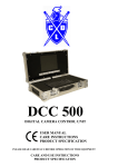
DCC 700 DIGITAL CAMERA CONTROL USER MANUAL CARE INSTRUCTIONS PRODUCT SPECIFICATION PLEASE READ CAREFULLY BEFORE OPERATION OF THIS EQUIPMENT CARE AND USE INSTRUCTIONS PRODUCT SPECIFICATION DESCRIPTION DIGITAL CAMERA CONTROL UNIT FOR DRAIN AND PIPELINE INSPECTION MANUFACTURER CRUSADE DESIGNS LTD. Unit 1 Upper Boat Trading Estate Upper Boat, PONTYPRIDD CF37 5BP UNITED KINGDOM Tel. 44 (0)1443 843030 fax 44 (0)1443 842005 www.crusadedesigns.com CONTENTS INTRODUCTION CONNECTING A CAMERA OPERATION SYSTEM CONNECTION RECORDING THE SURVEY BASE UNIT OPERATION FRONT PANEL CONTROLS SCRIPTWRITER PRELOADED PAGES EDITING OTHER FUNCTION KEY’S KEYBOARD KEY’S EDITING TEXT CARE INSTRUCTIONS HANDLING CLEANING MAINTENANCE TROUBLESHOOTING ROUTINE SERVICE FAULT FINDING PRODUCT SPECIFICATIONS Crusade Designs Ltd. reserves the right to make changes to the electrical, electronic, optical, mechanical, software and firmware specifications of its products without notification. This product carries a 12-month warranty against defective materials and workmanship without prejudice to customer's statutory rights. Crusade Designs Ltd. disclaims any responsibility for consequential loss or failure due to incorrect use or use with incompatible equipment. INTRODUCTION These instructions are limited to the use and care of the DCC 700 Base unit and are in no way intended to give guidance on the interpretation of data or the techniques of safe access to line entry points. The DCC 700 is designed for use with CRUSADE DESIGNS range of pipe inspection cameras. Cables supplied with any older CRUSADE DESIGNS MIC series base units fitted with 14 pin connectors are compatible without modification. Your supplier can advise on compatibility of other existing equipment and details of any modifications required. These instructions assume that the user is conversant with the basic operation of the various camera and tractor systems. CONNECTING A CAMERA / TRACTOR TO THE DCC 700 The Crusade series of camera’s and tractors may be connected to the DCC 700 base unit via its cable reel and link cable. The link cable is totally reversible as it is wired pin for pin. Please refer to the appropriate manual for each piece of ancillary equipment. Always ensure that none of the equipment is powered up when connecting or disconnecting a camera, light head or any cables or drums. OPERATION SYSTEM CONNECTION Assemble the camera, light rings, skid, tractor ETC. and connect them to the base unit. Before turning the system on please observe the following if you are using a generator. Please ensure it is producing the correct 110v ac voltage within plus or minus 10% and please let it operate for one minute before connecting the DCC 700 base unit to it. Ensure that all camera equipment is connected before switching the base unit on. Connect the mains lead to the 110v ac supply and press the main switch. Depress the power button pad to switch the base unit on. Use the remote supplied to switch the memory card recorder on and locate the record option. When this is located the camera picture will appear on the screen. Insert the CF card into the base unit slot. Depress the display button to produce the measurement display on the screen. Use the position button pad to place this display where you want it on the screen. If the DCC 700 cannot identify what camera it is connected to, a black screen with a message will be displayed. Depress the indicated button for colour or black and white camera . This will clear the screen and show the camera picture. The camera is now ready for use. If you wish to disconnect any item or change any item please switch the unit off before doing so, for example changing the light head or disconnecting the camera at the end of a run. TO RECORD THE SURVEY Insert a standard SD card (up to 4Gb in size) into the base unit located on the right-hand side of the lid (side view). Using the remote control supplied, press the power button. Follow the recorder’s instruction book to make a recording or to play back. BASE UNIT OPERATION FRONT PANEL CONTROLS POWER Switches unit on or off. OK LED indicates a supply is connected to the DCC 700 ON LED illuminates when power is on. ZERO Depress this button when the system is fully connected, the display is showing on the screen and only sufficient cable has been unwound from the cable drum to connect to the camera. This sets the absolute zero point for a full drum and is the datum for all measurements. Do not use when cable is unwound from drum. See also MEAS ZERO. INFO Depressing this button shows security details. LEFT Depressing this button moves a pan and rotate head left. It is only active while pressed. LAMPS Default position is off. Depressing this button cycles through OFF, ON and OVERIDE switching the lamps on, where applicable. Using in the over-ride position further increases the lamp intensity but shortens the bulb life. Please turn down the intensity when not needed. INTENSITY Rotating this knob clockwise increases the bulb intensity, where applicable. Please set this control to the lowest level needed for a good picture. TEAR This button pad has two functions. Depress this button when the cable has been pulled off the drum and you wish to start measuring from zero, e.g. At the start of the pipe run or between subsequent manholes. Depress and hold down this button when you wish to zero and insert a focal factor at the start of the pipe run, release it when the desired factor is showing on the screen. The measurement factor increases in 0.1 metre increments up to a maximum of 2.0 metre and then reverts to 0. UP Depressing this button rotates a pan and rotate head clockwise. It is only active while pressed. STOP Depressing this button stops the tractor drive system or, if already stopped, homes a pan and rotate head. DOWN Depressing this button rotates a pan and rotate head anticlockwise. It is only active while pressed. SPEED Rotating this knob clockwise will increase the speed of the tractor, rotating it anticlockwise will reduce its speed and when fully rotated anticlockwise will stop the tractor. In addition increasing speed past a crawl will automatically home a pan and rotate head. DISPLAY Default position is off. Switches measurement display on or off. FWD Depressing this button pad puts the tractor drive system into its forward drive mode and inserts the letter F onto the screen in front of the measurement figure. Please note depressing either FWD or REV while the tractor is in motion will cancel that drive mode, the F or R will be removed from the screen indicating that there is no drive mode connected and the tractor will Stop. RIGHT Depressing this button moves a pan and rotate head right. It is only active while pressed. REV Depressing this button pad puts the tractor drive system into its reverse drive mode and inserts the letter T on to the screen in front of the measurement figure. This indicates a 5 second delay to enable the operator to pick up the cable before the T changes to R and the reverse drive mode comes into operation. Please note depressing either FWD or REV while the tractor is in motion will cancel that drive mode, the F or R will be removed from the screen indicating that there is no drive mode connected and the tractor will Stop. FOCUS Lifting this switch will move the focal point of the camera forward. Depressing this switch will move the focal point of the camera backward. It is only active while held. SCRIPTWRITER The scriptwriter has 26 pages designated A to Z which can be selected individually by holding down the Ctrl key and pressing the corresponding letter key (A to Z) or in sequence by holding down the Fn (Function) Key and pressing Page Up or Page Down keys. This action will automatically display the page. Any page displayed on screen can be removed by the use of the Esc key. In this display mode all other keys are inoperative. PRELOADED PAGES Certain pages are preloaded at the factory but can be edited by the user to suit their own preferences. The initial page, shown only at switch on, cannot be edited as this contains information applicable to the base unit. I.E. version and ESN (Electronic Serial Number). The preloaded pages are shown below: A B C D E F G H Your company information page Survey Details Blank WATER 00% DISPLACED JOINT OPEN JOINT RADIAL CRACK LONGITUDINAL CRACK I J K L M N O P –Z COLLAPSE SILT/DEBRIS ROOTS SCALE/GREASE CONNECTION CHAMBER END OF SURVEY All these pages are left blank. EDITING Once a page has been displayed on the screen it can be edited by pressing the EDIT key (F1). In addition to this a grid of dots can be placed on the screen to show character positions. This is toggled on and off by the GRID key (F3). When displayed the grid has two sizes of dot, the large one indicates a space with a black background behind it and a small dot indicates a space with no background I.E. video. After editing the page it can either be saved by pressing the SAVE key (F4) or aborted by pressing Esc reverting to the original text, either key will exit the edit mode. OTHER FUNCTION KEY’S F5 CLS Will clear the whole of the screen to transparent blanks. F6 B/GND Turns background on off on a line-by-line basis. F7 SIZE Toggles through 3 sizes of character on a line-by-line basis. F8 INS LINE Inserts a blank line at the cursor all others moving down. F9 DEL LINE Deletes the line at the cursor all other moving up. KEYBOARD KEY’S Insert Fn Home Fn End Arrow Keys Backspace Del Tab Toggles between insert and overlay. Moves to start of line. Moves to end of line. Moves cursor around the screen. Deletes the character before the cursor all others move left. Deletes the character at the cursor all others move left. Moves the cursor 8 places right for small characters and 4 places for large. EDITING TEXT When entering the edit mode the keyboard will be set up as follows: Caps Lock Character size Cursor on for uppercase; can be taken off by pressing the Caps Lock key. set to intermediate; can be changed by the SIZE key (F7). set to overlay mode; can be changed by the Insert key. While editing the cursor has two modes a large one in overlay, where characters overlay any that were there previously, and a small one in insert mode, where characters will be inserted, and the rest of the line moved right. As was mentioned earlier a space can have a background or not. Typing a space will produce a space with a background. Holding down the shift key while typing a space will produce a space with no background. CARE INSTRUCTIONS HANDLING The reliability and lifetime of this camera will depend in large measure on the care it receives. It has been designed for the harsh environment of drain inspection but, as with any other equipment, it will repay a little care taken in its use and regular cleaning and inspection afterwards. CLEANING All exposed metal parts are either anodized aluminium or plastic. Cleaning is always easier and more effective when the deposit is fresh. DO's All items should be cleaned with a damp cloth moistened with a mild detergent solution (e.g. washing-up liquid). Pay particular attention as silt, sand and similar material can be quite abrasive. A damp toothbrush or a small paintbrush are ideal for cleaning most of the recesses on all items. Use a soft lint-free cloth or proprietary lens cleaning tissue to clean any smears left on the monitor glass. DO NOT's The base unit should not be cleaned by immersion. Do not scrub the monitor screen to remove particulate material as you may scratch it. Scratches on the monitor screen cannot be removed but particulate matter can be removed by rubbing with a cloth moistened with alcohol. Petroleum-based products or proprietary electrical equipment cleaners such as WD40 may contain solvents that attack non-metallic parts and should not be used. The electrical connections in the mating sockets are gold plated so should not be abraded. Do not use a high-pressure water-jet or steam cleaner. MAINTENANCE There are no user serviceable items inside any of the equipment covered by these instructions. Aside from regular cleaning, the only user serviceable items are replacement of recorder’s monitors or keyboards. TROUBLESHOOTING The picture flashes on and off whilst the camera is moving. Suspect a cable or connector somewhere in the system and check that all connectors are right home, see manuals on each respective camera component. No image on the monitor screen. Switch the recorder on. The monitor screen is black with an error message. Either the equipment has not been completely connected prior to switching on, (see system connections), or an old measurement drum system has been connected, in the latter case follow the error instructions. The monitor screen is still black. Depress the info button pad on the base unit control panel. The screen should display the security information. Depress the info button pad again, if the camera picture flashes momentarily onto the screen then the camera and monitor are working but the recorder or scriptwriter, or their wiring, are not. Please contact the factory to make arrangements for your recorder to be repaired. If the monitor screen still stays black then please contact the factory. If the distance measurement stays at zero whilst the cable is unreeling then replace the link cable. If this cures the problem then repair or return the link cable. If the problem is still present please contact the factory. ROUTINE SERVICE Regularly check all cable’s for splits both small and large, immediately cover these with amalgamating tape to keep moisture out. This will prolong the life of your cable without upsetting the measurement system. Regularly check cable plug’s. Power fault investigation should only be undertaken by a qualified technician. SPECIFICATION Width Height Depth Weight Voltage: Link Cable Power Cable 560 mm 165 mm 320 mm 14 kg 110/230 volt 10 meters 14 pin T/B. plug to plug Approx., 2 meters IEC Text Writer Characters per line Lines per screen Keyboard B/W 24 page + security screen 50 Single width, 25 Double width 16 Single height, 8 Double height I.B.M. PS2 Compatible Mini Keyboard Monitor Native Resolution Contrast Ratio Viewing Angle Brightness Colours Screen Format 10.4” TFT LCD 640 x 480 300:1 60 degrees 300 Cd/m2 16.7 million 4:3 Video Recorder Record Media Type Record Media Capacity MPEG4 compression Recording Standard SD Cards SD cards up to 4Gb Compliance: Electromagnetic Compatibility Directive 89/336/EEC Electrical Equipment Directive 73/23/EEC.