1
GSM Adapter Mini
Installation and User Manual
for module version 2.02 and higher
Rev 1.2 01.06.2010
Application area
Connecting an alarm control panel
monitoring
station
with
Contact
communication through GSM network
Security reserve (secondary signal) for the
already existing PSTN communicators
Wired telephone adapter for flats, houses,
cottages
A simple emergency alarm for elderly sick
people by picking up the receiver
Remote diagnostics of centres built to long
distances
to
ID
Features
Analogue telephone line simulation to transfer Contact ID signals and voice
Handling of landline (PSTN), in case of its cessation altering to GSM line simulation
Generating SMS message from the Contact ID codes of monitoring station reports (alarm,
arming, disarming…)
Automatic dial of pre-set telephone number as a result of picking up the receiver (emergency
call function)
Bell 103 / V.21 digital data communication
The alarm control panel becomes programmable through GSM data call (remote maintenance,
downloading event code, etc.)
Table of contents
1 Main functions of the GSM Adapter................................................................................. 3
1.1 Additional features ................................................................................................ 3
2 Setting the parameters of the Adapter............................................................................. 3
2.1
Module state monitoring ....................................................................................... 4
2.1.1 Communication details .................................................................................. 5
2.2 Parameter settings ................................................................................................ 6
2.2.1 Setting phone numbers ................................................................................. 6
2.2.2 SMS settings - sending SMS messages in case of alarms or other events... 7
2.2.3 Call filter - receiving calls through the GSM network ..................................... 9
2.2.4 Remote programming with BELL 103 / V.21 format .................................... 10
3 External elements and functions of GSM Adapter Mini ................................................. 11
3.1 SIM card case ..................................................................................................... 11
3.2 LED signals ......................................................................................................... 11
3.3 Antenna connection ............................................................................................ 11
3.4 Module wiring ...................................................................................................... 12
3.5 Function of the “IN” (DIRECT GSM) input ........................................................... 12
4 Setting the alarm control panel...................................................................................... 13
4.1 Further notes....................................................................................................... 13
5 Installation guide ........................................................................................................... 13
5.1 Mounting ............................................................................................................. 13
5.2 Putting into operation .......................................................................................... 14
6 Technical details ........................................................................................................... 14
6.1 Technical specification ........................................................................................ 14
6.2 Generated telephone line specification ............................................................... 14
6.3 Content of the package ....................................................................................... 14
6.4 The manufacturer’s contact................................................................................. 14
7 Example of application .................................................................................................. 15
2
1 Main functions of the GSM Adapter
The main function of the GSM Adapter Mini is to interface to GSM network an alarm
system that can report to security monitoring station through PSTN telephone line.
The GSM Adapter makes possible the installation of alarm systems in places where
landline (PSTN) is not available, but it is necessary to send report to security monitoring
station.
By means of GSM transmission, the adapter improves the reliability of alarm reporting in
cases when the PSTN alarm transmission does not work or fails (e.g. when the phone
lines are tampered or the telephone service is suspended due to technical reasons).
1.1
Additional features
Receiving incoming telephone calls, possibility of restricting incoming calls
Setting installations to sub-stationary networks
Synchronizing PSTN and GSM telephone calls with different prefix numbers
Forwarding information of GSM account balance of prepay SIM card
Converting alarm codes into SMS messages
Emergency call function
Interfacing voice diallers
Remote programming of alarm systems
2 Setting the parameters of the Adapter
Setting the parameters of the module is possible via USB connection using the
„GSM_Adapter_Remoter_vxxx.exe” software. The language of the program can be
selected by clicking on the language icons in the bottom right corner of the program
window.
If necessary, the version of the programming software can be updated by clicking on the
“Search for program updates” link on the “Connection” page. The update procedure
requires internet connection. It can be also set here, if the program should search for
updates automatically on each opening, or this is performed manually by clicking on the
search link.
Setting parameters through USB connection:
Start „ GSM_Adapter_Remoter_vxxx.exe” software
Power up the module
Connect the module to the PC using the enclosed USB cable
When connection is established a green tick icon appears in the upper right corner
of the program window and module version is displayed in the program header
After this, downloading, uploading and monitoring functions become available
When programming is finished, disconnect the USB cable from the module
3
2.1
Module state monitoring
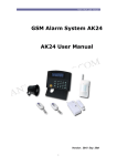
When connected, the module’s current state can be monitored in the “Module state”
window. The following information are displayed: the availability of landline phone, state
of the input, the GSM line state, the GSM signal strength and the module state
messages. The module message window can be cleared by pressing "Clear message
window" button.
PSTN Line:
if there is a PSTN phone line connected to the correspondent
module terminals, then it is displayed whether it is available or
not
IN1:
shows the state of the IN contact input
GSM line state:
displays the state of the GSM line, whether it is in use or not
GSM signal strength: displays the current GSM signal strength on a 31-point graphical
scale
Module version:
the version of the connected module is displayed in the header
of the program window. The example in the picture above shows
the following information:
GSM Adapter Mini:
v2.02:
2009.08.12:
4
module type
firmware version
firmware issue date (12.08.2009)
2.1.1 Communication details
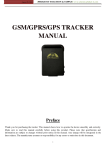
By pressing the “Communication details” button a new window appears where the
tasks and processes running in the module can be traced.
Operations performed
by the Adapter
Internal
processes of the
Adapter
Summary of recognized
Contact ID reports
DTMF communication
passing through the
Adapter
In the left side of the window (divided part) the bidirectional communication is displayed,
while in the right side the module’s internal processes are shown.
Clear windows:
clears the content of all windows (does not have effect on the
module’s operation, only on display)
Save to file:
saves the whole content of all windows to text file
Stop/Start:
stops and starts the data flow being displayed (does not have
effect on the module’s operation)
Close:
closes the communication details window.
5
2.2
Parameter settings
In this menu saved settings can be loaded from files, saved to files or loaded to or from
the module or compared using the corresponding icon buttons.
For the basic operation of the unit, no setting is necessary. So GSM line simulation
and handling of PSTN line are automatic.
However, if it is requested, in order to reach the additional functions of the adapter as
detailed in the following sections, it is required to set certain parameters (e.g. the owner’s
phone number, the number to be dialed to access the external PSTN line, the texts of
SMS messages, etc.)
2.2.1 Setting phone numbers
User phone numbers
Two user phone numbers can be set to which the GSM Adapter sends SMS message
with the text specified in "SMS settings" window, when the Adapter receives from the
alarm control panel a Contact ID event code that is also specified in the list, in the row
assigned to the relevant SMS text.
6
SMS forward Nr. - forwarding incoming SMS messages
It is possible to forward messages incoming to the Adapter’s SIM card up to two owner or
user phone numbers. This makes the use of cheap non-subscription cards safe.
If the incoming SMS has been successfully forwarded, it will be deleted from the SIM
card to make space for further incoming messages.
Attention! Never enter here the phone number of the SIM card placed into the
module, because this would initiate an infinite loop of SMS sent to itself right after
the first incoming SMS, causing significant expense!
Automatic dial number
This function can be used in certain, specific tasks (e.g. emergency telephone calls).
The appropriately set module shall immediately initiate a call to the preset number
through GSM network when the receiver is picked up.
Setting a prefix number necessary to access external PSTN line in case of
using a telephone subsystem
If the module’s PSTN line input is connected to a telephone subsystem where the dialing
of a prefix number (e.g. 9) is necessary to access the external PSTN main line, this
number must be entered on the adapter. So the module omits the prefix number (e.g. 9)
in case of telephone calls through GSM network, however, it naturally initiates the call
starting with the prefix number (e.g. 9) in case the call is directed through a PSTN line.
Cases when the prefix number necessary to access GSM and PSTN is different
Another prefix number can be set for the module to insert in front of the dialed number in
all those cases when the call is directed through GSM network. (e.g. if the panel calls the
PSTN local number without the area code, a prefix can be assigned that is necessary to
initiate calls through GSM network.)
(This function came to be important because of some special characteristics of foreign
PSTN networks.)
Voice dialler support
One main characteristic of speech diallers is that they start playing the message in a
certain time, if no ringtone can be heard in the line.
By setting this function, you will hear a simulated tone signal until the real ringtone can
be heard. This way can be avoided that the speech dialler starts to play the message
before the call is received.
2.2.2 SMS settings - sending SMS messages in case of alarms or other events
The GSM Adapter continuously watches the calls initiated through the GSM network, and
notices the reports of CONTACT ID or ADEMCO Express formats. If it observes any of
the specified event codes (maximum 10), it will send an assigned SMS message to one
or two telephone numbers that has been set by the user. The text of the message to be
sent can be set by the user.
7
The event codes can be found in the alarm control panel’s installer’s manual. The event
codes in the list must consist of 4 hexadecimal digits each, where the first digit makes
the difference between new event ("1") and restoration event ("3").
When entering event codes in the list, code groups can be specified as well with the use
of "" character within the codes. This means it is indifferent what character is received
from the alarm control panel in the place substituted with "" character but the rest of the
code corresponds to the one in the list, the relevant event will be transmitted.
Note: the module does not perceive signals sent through the PSTN line.
Note:
in
case
of
entering
ADEMCO-Express
event
codes
in
the
“GSM_Adapter_Remoter_vxxx.exe” software, double 0 shall be inserted before the
code. E.g. 31 = in case of alarm, you shall enter 0031 in the list.
Sending SMS messages on event, without being connected to a monitoring
station
If reporting to a monitoring station is not requested, it is still possible to send SMS
messages in case of some events. To do this, enter 123456789 instead of the telephone
number of the monitoring station into the alarm control panel. In case of alarm, the alarm
control panel will dial this number and the GSM Adapter module will not initiate a real
phone call, but will simulate the operation of the monitoring station (gives out handshake
signals and acknowledges CONTACT ID and ADEMCO Express event codes).
This way it is possible to send SMS messages from the received signals as described in
the previous section.
8
2.2.3 Call filter - receiving calls through the GSM network
The GSM Adapter Mini is able to manage calls coming in through the GSM network, and
to ring up devices (telephone, alarm system) connected to it. With this, it can receive
incoming GSM calls in places where there is no PSTN line extension by means of a
simple analogue telephone.
This function works only if there is no PSTN line connected to the module and the IN
(DIRECT GSM) input is not activated (short-circuited).
It is also possible to filter incoming voice calls by phone number, which means the
Adapter will accept incoming voice calls only from the specified phone numbers. In this
case voice calls initiated from other phone numbers will be rejected.
Attention! In case of using telephone number filtering, do not specify the inland area
changing prefix before the telephone number, only the area code and the phone number.
(The telephone uses international format +3630… while displaying telephone numbers.
The module compares the received telephone number with the filtered telephone number
by starting to compare them from the last digits. The module handles the two numbers as
identical even if +36 is left out.
There is also a possibility to limit the duration of incoming calls between 0 and 25
minutes/call. If value 0 is entered, the duration of incoming calls is unlimited.
9
2.2.4 Remote programming with BELL 103 / V.21 format
The GSM Adapter Mini uses GSM voice channel, which has 13 kbit/s bandwidth, for calls
and monitoring station signals. However, the original sound source is 64 kbit/s, which
has been composed to the mentioned value so as to be able to make use of radio
channel capacity. Due to this procedure, it is impossible to transmit periodic and constant
amplitude signals, like the FSK modulation of Bell 103 coding in a secure way. For this
reason, the panel’s data communication goes through GSM data channel. Naturally,
remote diagnostics operates with call back function too, at the expense of the Adapter’s
SIM card. If this function is necessary, then enable “Enable BELL 103 callback” option.
It is also possible to filter incoming data calls by phone number, which means the
Adapter will accept incoming data calls only from the specified phone numbers. In this
case data calls initiated from other phone numbers will be rejected.
To be able to program remotely alarm control panels with connected GSM
Adapters, a GSM modem is necessary (T.E.L.L. GT64 recommended) on the caller
side! The SIM cards placed in the modem and Adapter must support both way
(send and receive data) GSM data call service (CSD).
10
3 External elements and functions of GSM Adapter Mini
3.1
SIM card case
The cover can be opened by pulling horizontally towards the LED display on its marked
end. Insert the SIM card here and replace the cover after doing the following
preparations:
Before starting to setup the Adapter, insert the SIM card into a mobile phone and perform
the following settings:
Make sure that the number of the SMS message centre is set correctly on the SIM
card, that is SMS can be sent from the phone.
Disable PIN code request on the SIM card so that it shall not prompt for a PIN code
on turning the unit on
Delete the unnecessary SMS messages from the card.
The SIM card necessary for the operation of the unit can be purchased from any GSM
service provider.
The Adapter is independent of GSM providers.
3.2
3.3
LED signals
RED is continuously lit
Indicates that the module is powered up but not
connected to the GSM network. (If it lasts longer than 30
seconds, check the SIM card and the antenna
connection)
GREEN blinks slowly and
impulsely
The module is connected to the GSM network is ready to
communicate.
GREEN is continuously lit
Indicates that a call is in progress through the GSM
network
RED and GREEN blink
alternately
Indicates that the download process of parameters was
unsuccessful. (e.g. download was interrupted)
Download has to be repeated.
Antenna connection
The antenna must be fixed to the module’s FME (pin) connector. The antenna in the
package provides good transmission under normal reception circumstances. In case of
occasionally occurring GSM signal strength problems or/and wave interference (fading),
use another type of antenna or find a more suitable place for the Adapter.
11
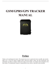
3.4
Module wiring
V+
VG1
G2
T1
T2
IN
S3
S2
S5
Supply voltage 9-24V DC
Supply voltage negative polarity (GND)
Simulated line output from the GSM system (to the alarm panel’s TIP input)
Simulated line output from the GSM system (to the alarm panel’s RING input)
Landline (PSTN) input
Landline (PSTN) input
Direct GSM (to activate, connect to V-)
Reserved
Reserved
Reserved
Attention! If the metal housing of the alarm control panel on which the antenna is
mounted is connected to the protective ground then it is necessary to connect the
protective ground to the GSM Adapter module's V- terminal as well.
3.5
Function of the “IN” (DIRECT GSM) input
Short-circuiting the IN input (to V- terminal), the module switches over to GSM
transmission, i.e. irrespective of the existence of an analogue phone line, the Adapter
initiates the call through the GSM network. Apart from this, it blocks and rejects incoming
calls to the Adapter. This ensures the call transmission in case there is some fault in the
telephone system or subsystem, i.e. if the PSTN line seemingly works but the alarm
system cannot connect to the monitoring station through the PSTN network. Most alarm
systems can be programmed activate a PGM output after a certain number of
unsuccessful dialing attempts. If this PGM signal arrives to the IN1 input of the Adapter,
i.e. the PSTN cannot be used, the unit will initiate the next call through the GSM network.
12
4
Setting the alarm control panel
Check the following settings on the alarms system:
The reporting format must be set to “CONTACT ID” or “ADEMCO Express”.
The phone numbers of the monitoring station must be specified containing the
area codes as well, so that they can be called from the SIM card through the
GSM network
Set the dialing to TONE mode
4.1
Further notes
The Adapter does not know in advance the length of the phone number to be dialled,
therefore do not wait too long before entering the next digit, because if you do so the
module might suppose that the dialling has already finished. (The Adapter expects at
least 7 digits, and does not start dialling until they are entered. It starts calling a
number of 7 and 10 digits after a 5 second pause. In case of 11 or more digits, the
Adapter starts dialling after a 2 second pause). This does not cause problems for
alarm control panels due to fast and automatic dial but needs attention on manual
dialling.
Telephone numbers shorter than 7 digits can be dialled by entering # after the
number.
5 Installation guide
Before installation verify the future environment of the Adapter:
5.1
Check the GSM signal strength using your mobile phone. It may happen that the
signal strength is not sufficient in the desired installation place. In this case you have
possibility to change the planned installation place before mounting.
Do not mount the unit in places where it can be affected by strong electromagnetic
disturbances (e.g. near electric motors, etc.).
Do not mount the unit in wet places or places with high degree of humidity.
Mounting
Suggested installation method: the GSM Adapter should be placed into the same metal
housing as the alarm control panel. Drill a hole on the metal housing for the FME
connector. Choose the drill size appropriate for the FME base part. Fix the FME base
with the enclosed screw nuts into the housing. Ensure that the FME base and the metal
housing has galvanic connection.
In case of plastic housing or weak GSM signal strength it may be necessary to use
another (directed) type of antenna.
Attention! If the metal housing of the alarm control panel on which the antenna is
mounted is connected to the protective ground then it is necessary to connect the
protective ground to the GSM Adapter module's V- terminal as well.
13
5.2
Putting into operation
Make sure the SIM card is placed into the module properly.
Enable the caller identification service on the SIM card at the GSM service
provider (a few types of SIM cards do not have this function enabled by default).
Make sure the antenna is fixed properly in the Adapter.
Make sure the wiring is done as earlier instructed.
The device can be powered up (9-24 VDC). Make sure that power supply is sufficient
at the load of both the alarm control panel and the Adapter. The quiescent current of
the Adapter is 200mA, however it can reach up to 500mA during communication.
6 Technical details
6.1
Technical specification
Supply voltage:
Maximum current consumption:
Operating temperature:
Transmission frequency:
GSM phone type:
Dimensions:
Net weight:
Gross weight (packed):
6.2
Generated telephone line specification
Line voltage:
Line current:
Line impedance:
Ringing voltage:
Dial tone:
6.3
48 V
25 mA
600 Ohm
±72V (25 Hz)
400 Hz
Content of the package
6.4
9-24 VDC
500mA
-20ºC — +70ºC
GSM 900/1800 MHz, 850/1900 MHz
Simcom SIM340
84x72x32 mm
200g
300g
GSM Adapter Mini + terminal connector
GSM 900 MHz / 1800 MHz antenna
User manual, warranty card
CD
USB A-B cable
The manufacturer’s contact
T.E.L.L. Software Hungária Kft
4034 Debrecen, Vágóhíd u. 2.
Hungary
Tel.: +36-52-530-130
Fax.: +36-52-530-131
Web: www.tell.hu
14
7 Example of application
Demand:
Connecting the alarm control panel to monitoring station
Information on balance to the owner about the prepay card (Tel: +36-30-123-4567)
SMS to the owner about burglar alarm (Tel: +36-30-123-4567)
Start the “GSM_Adapter_Remoter_vxxx.exe” application, main steps:
1.
2.
3.
4.
5.
Connect the module to the PC through USB
(When connection is established a green tick icon appears in the upper right corner
of the program window and module version is displayed in the program header)
Select “Parameter settings“ menu
Set the demanded parameters:
on “Phone numbers” page -> User 1.:
0036301234567
SMS forward Nr. 1.: 0036301234567
on “SMS settings“ page -> event code: 1130 SMS message: ALARM $
Press “Write parameters to module” button
Disconnect from USB
15