1
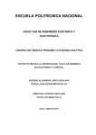
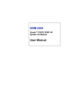
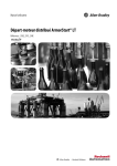
Notes on the use of
Kentech Instruments Ltd.
9-Channel Pulser System
Serial number J0502011
26th July 2005
Kentech Instruments Ltd.,Unit 9,Hall Farm Workshops, South Moreton,Oxon OX11 9AG, UK UK
Tel: 01235 510748
UK Fax: 01235 510722
VAT Registration number: GB394526620
Int. Tel: +44 1235 510748
Registered in England No. 1742794
Int. Fax: +44 1235 510722
Registered office: 6a 1st Floor, Popin Business Ctr., South Way, Wembley, London HA9 0HF, UK Email: [email protected]
Directors: P.A. Kellett B.A.(Oxon), A.K.L. Dymoke-Bradshaw PhD, J.D. Hares PhD.
Web: http://www.kentech.co.uk/
9-Channel Pulser System
i) Caution
9-Channel Pulser System, serial number J0502011
This equipment is a research tool that has been intentionally designed to generate high energy
electromagnetic pulses and the EM emissions will be highly sensitive to the load applied by the
user. Within the EU it is suitable for use only in a sealed electromagnetic environment, unless it is
used in a system that has been verified by the system builder to comply with EU directive
89/336/EEC.
With an appropriate load and adequately insulated connecting leads, the unit is safe for use by an
educated user in a laboratory environment. You are warned however that the radiation from the
system with an antenna or inappropriate load attached can damage sensitive equipment and corrupt
data stored in computer and microprocessor based systems. It can cause terminal failure of vital
medical electronic systems such as pacemakers. This equipment is be supplied on the understanding
that the user will analyse these risks, accept responsibility for them and take appropriate precautions
in the use of this instrument.
The output from this pulse generator will destroy many types of power attenuators and electronic
test equipment. It is the users responsibility to ensure that any apparatus connected to the output is
suitably rated.
Kentech Instruments Ltd accepts no responsibility for any damage or liabilities incurred in the
operation of this equipment.
Please read the manual before applying power.
THERE ARE DANGEROUS HIGH VOLTAGES (1kV) PRESENT IN THIS PULSER WHEN
THE UNIT IS OPERATING. DISCONNECT THE POWER SUPPLY BEFORE REMOVING THE
COVERS.
Kentech Instruments Ltd
Page 2 of 28
July 2005
9-Channel Pulser System
ii) Disclaimer
This equipment contains high voltage power supplies. Careless can result in electric shocks. It is
assumed that this highly specialised equipment will only be used by qualified personnel.
Kentech Instruments Ltd accepts no responsibility for any electric shock or injury arising from use
or misuse of this product. It is the responsibility of the user to exercise care and common sense with
this highly versatile equipment.
The main output can be very dangerous, particularly when the pulser is triggered at a high
frequency. Take great care to insulate the output adequately.
Kentech Instruments Ltd
Page 3 of 28
July 2005
9-Channel Pulser System
1.
Introduction
Our range of solid state high voltage pulse sources allows very high voltage, fast rising pulses to be
obtained from compact bench top units. Our avalanche technology allows the generation of 10kV
voltage pulses rising in 100ps into 50Ω. Our range of FET pulse generators provides subnanosecond switching speeds, kilovolt amplitudes and repetition rates in excess of 1MHz. The
performance of our compact, convenient and reliable pulsers is to our knowledge exceeded only by
laser driven photoconductive switches in terms of voltage switching speeds and versatility. These
pulsers will find applications in many fields such as high speed camera research, electro-optic
switching, triggering systems, time of flight mass spectroscopy and radar.
Kentech Instruments Ltd
Page 4 of 28
July 2005
9-Channel Pulser System
2.
Description of the 9-Channel Pulser System
The Kentech Instruments 9-Channel Pulser System (J0502011) is designed to generate -3kV pulses
on nine separate outputs, each with a programmable delay of up to 50ns and a programmable bias
voltage in the range +/-500V. The Pulser System is controlled and monitored via a serial interface.
The Pulser System consists of:
• nine high voltage pulse generators (CPS3/M1) which produce the HV output pulses;
• one CPS3 Master Control Unit (MCU) which generates the bias voltages and the delayed HV
trigger pulses required by the pulse generators;
• nine Pulse Forming Modules (PFM) which shape the pulse as required by the user;
• RF and power cables;
• LabView control interface software to control the Pulser System.
CPS3 Master Control Unit
Made in England by
Kentech Instruments Ltd
www.kentech.co.uk
Interlock
Triggered
HV trigger outputs
1
2
CPS3/M1 High voltage pulse generator
Made in England by
3
MCP bias (+/-500V)
Kentech Instruments Ltd.
5
6
7
MCP bias (+/-500V)
Kentech Instruments Ltd.
Triggered
Trig. amp. output
Power
Timing monitor
Low level
trig. input
High level
trig./bias input
Ext./monitor
DC bias 500V
MCP bias (+/-500V)
Kentech Instruments Ltd.
Trig. amp. output
Low level
trig. input
High level
trig./bias input
Ext./monitor
DC bias 500V
Trig. amp. output
Low level
trig. input
High level
trig./bias input
Made in England by
MCP bias (+/-500V)
Kentech Instruments Ltd.
MCP bias (+/-500V)
Trig. amp. output
Trig. amp. output
High level
trig./bias input
Low level
trig. input
High level
trig./bias input
Ext./monitor
DC bias 500V
Triggered
Power
Timing monitor
MCP bias (+/-500V)
Trig. amp. output
Timing monitor
High level
trig./bias input
Ext./monitor
DC bias 500V
MCP bias (+/-500V)
Kentech Instruments Ltd.
HV pulse output
(>6kV, 50Ω)
CPS3/M1 High voltage pulse generator
Made in England by
MCP bias (+/-500V)
Kentech Instruments Ltd.
www.kentech.co.uk
Triggered
Trig. amp. output
Power
Timing monitor
Triggered
Trig. amp. output
Timing monitor
High level
trig./bias input
Ext./monitor
DC bias 500V
!
HV pulse output
(>6kV, 50Ω)
HV pulse output
(>6kV, 50Ω)
!
Low level
trig. input
HV pulse output
(>6kV, 50Ω)
CPS3/M1 High voltage pulse generator
Made in England by
Ext./monitor
DC bias 500V
Ext./monitor
DC bias 500V
Kentech Instruments Ltd.
Power
Timing monitor
!
Low level
trig. input
High level
trig./bias input
CPS3/M1 High voltage pulse generator
Made in England by
www.kentech.co.uk
Triggered
Low level
trig. input
!
www.kentech.co.uk
Power
Timing monitor
www.kentech.co.uk
Triggered
HV pulse output
(>6kV, 50Ω)
CPS3/M1 High voltage pulse generator
Trig. amp. output
!
Kentech Instruments Ltd.
Power
Timing monitor
Ext./monitor
DC bias 500V
Triggered
HV pulse output
(>6kV, 50Ω)
CPS3/M1 High voltage pulse generator
!
Made in England by
Power
Timing monitor
www.kentech.co.uk
Triggered
MCP bias (+/-500V)
Kentech Instruments Ltd.
!
www.kentech.co.uk
Power
CPS3/M1 High voltage pulse generator
www.kentech.co.uk
Triggered
HV pulse output
(>6kV, 50Ω)
CPS3/M1 High voltage pulse generator
Power
Trigger input
(5V, 50ohms)
9
Made in England by
www.kentech.co.uk
!
Made in England by
8
CPS3/M1 High voltage pulse generator
Made in England by
www.kentech.co.uk
Power
4
RS232
Low level
trig. input
High level
trig./bias input
Ext./monitor
DC bias 500V
!
HV pulse output
(>6kV, 50Ω)
Low level
trig. input
HV pulse output
(>6kV, 50Ω)
Figure 1 9-Channel Pulser System
Kentech Instruments Ltd
Page 5 of 28
July 2005
9-Channel Pulser System
3.
9-Channel Pulser System Specification
3.1.
Pulse Generator (CPS3/M1) Specification
Output pulse amplitude:
Permitted bias voltage:
Timing monitor:
Maximum rep rate:
Connectors & Interface:
Size:
Power supply:
Indication:
3.2.
Pulse Forming Module (PFM) Specification (when used with CPS3/M1)
Output pulse amplitude:
Rise time:
Fall time:
Flatness of top:
Pulse width:
3.3.
≥ 6kV negative pulse into 50Ω
-500V to +500V
≥ 5V negative pulse
10Hz
Low level trigger input (BNC)
Trigger amplifier output (SHV)
External bias input OR monitor (SHV)
High level trigger and bias input (SHV)
Timing monitor (SMA)
HV pulse output (TNC)
MCP bias output (LEMO-'00' series)
Mains Power (IEC rear panel)
235mm wide x 98mm high x 30.6mm deep without PFM
110 – 240V AC, 50-60Hz, ~20W
Power led
Trigger led
≥ 3kV near square negative pulse
< 150ps
< 250ps
< 5%
380 - 400ps near flat top, approx 500ps fwhm
Master Control Unit (MCU) Specification
Nine independent bias supplies
Bias voltage range:
-500 to +500V
Bias voltage monitor tolerance:
± 1% with 1GΩ load (± 5% with 10MΩ load)
Maximum bias current:
50μA
Bias current monitor tolerance:
± 1%
Nine independent current trips
Bias trip current tolerance:
± 5μA
Nine independent delay generators
Maximum delay:
50ns
Delay resolution:
25ps
RS232 settings:
Connectors & Interface:
Maximum rep rate:
Kentech Instruments Ltd
9600 baud
Low level trigger input (BNC)
RS232 port (9 way socket)
Interlock connector (LEMO coaxial)
9 x HV trigger and bias outputs (SHV)
Mains Power (IEC rear panel)
10Hz
Page 6 of 28
July 2005
9-Channel Pulser System
Power supply:
Size:
Indication:
3.4.
System Specification
Jitter between outputs:
Power consumption:
3.5.
110 – 240V AC, 50-60Hz, <20W
19" wide x 3U tall x 400mm deep
Power led
Trig led
<20ps rms
<250W
Control Interface
1 x Labview driver (virtual instrument) for Master Control Unit
Commands include:write desired value for channel n bias voltage
read back desired value for channel n bias voltage
read measured value from ADC for channel n bias voltage
read measured value from ADC for channel n bias current
set bias current trip level
read back trip status
enable all bias voltages individually
disable all bias voltages individually
read back bias enable status
write desired value for delay n
read desired value for delay
enable all trigger outputs individually
disable all trigger outputs individually
read back trigger enable status
read interlock input status
3.6.
Cables
9 x N type to SMA 50Ω coaxial output cables 2m length
9 x SHV to SHV 50Ω coaxial trigger leads 2m length
9 x SHV to SHV 50Ω coaxial trigger short leads (30cm for stand-alone operation)
1 x Lemo connector with 2m flying lead (for interlock input)
10 x US AC IEC power leads.
Kentech Instruments Ltd
Page 7 of 28
July 2005
9-Channel Pulser System
4.
Instrument Description
4.1.
Master Control Unit
The Master Control Unit (MCU) consists of a microcontroller module, a high voltage trigger
generator module and nine Bias/Delay channels. The MCU may be controlled by a PC connected to
the front-panel RS232 port. The MCU has a front panel Interlock socket; the interlock signal must
be shorted to ground in order to enable the bias voltages on the HV trigger output connectors.
CPS3 Master Control Unit
Made in England by
Kentech Instruments Ltd
www.kentech.co.uk
Interlock
HV trigger outputs
1
2
3
4
5
6
7
8
9
Triggered
RS232
Trigger input
(5V, 50ohms)
Power
Figure 2 MCU Front Panel
The MCU is triggered by a 5V positive edge on the Trigger input (BNC) connector. A high voltage
pulse is generated and split into each of the nine channels. These 500V pulses propergate in parallel
through the nine programmable delay channels and are finally combined with the programmable
bias voltages at the HV trigger output (SHV) connectors.
An EEPROM Write Enable button has been fitted to the rear of the MCU. This button should be
used only when reprograming the calibration data. Contact Kentech Instruments for more
information.
The MCU contains nine separate bias generators which can be individually programmed to give
different bias settings on each channel. A single current limit can be set for all the channels. If the
bias current on any channel exceeds this limit, the bias will be disabled.
Each channel has its own programmable delay generator. The user may delay each output pulse by
up to 50ns, with a resolution of approximately 25ps.
4.2.
CPS3/M1 pulse generators
The CPS3/M1 pulse generators produce ≥6kV negative unshaped pulse with a rise-time of
approximately 100ps. The Pulse Forming Modules (PFMs) shape the output waveform to produce a
≥3kV negative pulse with a length of approximately 500ps.
Kentech Instruments Ltd
Page 8 of 28
July 2005
9-Channel Pulser System
CPS3/M1 High voltage pulse generator
Made in England by
MCP bias (+/-500V)
Kentech Instruments Ltd.
PFM
www.kentech.co.uk
Power
Triggered
Trig. amp. output
Timing monitor
!
Low level
trig. input
High level
trig./bias input
Ext./monitor
DC bias 500V
PFM output
(N)
HV pulse output
(>6kV, 50Ω)
Figure 3 CPS3/M1 Front Panel
Note: these pulse generators must NOT be operated without a Pulse Forming Module. Operating
without proper termination may damage the equipment.
As part of the Nine-Channel Pulser System, each CPS3/M1 pulse generator is triggered by one of
the HV trigger output signals from the MCU. This signal is fed into the pulse generator's High level
trig./bias input (SHV) connector (see Figure 4). Within the pulse generator, the high voltage trigger
signal is stripped away from the bias and used to excite the avalanche transistor stacks to produce a
-3kV output pulse. This output pulse is then recombined with the bias within the Pulse Forming
Module.
CPS3/M1 & PFM
Main stacks
Trigger stack
PFM
Low level
trig. input
(BNC)
Trig. amp. output
(SHV)
High level
trig./bias input
(SHV)
HV trigger outputs
(SHV)
MCU
Timing monitor
(SMA)
Input
Oscilloscope
PFM output
(N)
Trigger input
(SMA)
User equipment
Ext./monitor
DC bias 500V
(SHV)
HV input
>=1GΩ
Voltmeter
Figure 4 CPS3/M1 Pulser System Operation
The user may monitor the timing and amplitude of the output pulse by observing the Timing
monitor (SMA) output. The output signal at this point is approximately 5V into 50Ω for a 3kV
output pulse.
The bias voltage may also be monitored at the Ext./monitor DC bias 500V (SHV) connector. The
impedance of the monitoring circuit should be ≥1GΩ.
4.3.
Use of the CPS3/M1 in Stand-Alone Operation
The CPS3/M1 may be triggered directly from a low voltage signal when not used as part of this
pulser system. In stand-alone operation, a HV trigger signal is produced within the pulse generator
Kentech Instruments Ltd
Page 9 of 28
July 2005
9-Channel Pulser System
and is available at the Trig. amp. output (SHV) connector. This trigger signal must be connected
directly to the High level trig./bias input (SHV) connector (see Figure 5). If a bias voltage is
required at the output, it must be generated by external equipment and introduced at the
Ext./monitor DC bias 500V (SHV) connector. The bias will be combined with the HV output pulse
within the PFM.
CPS3/M1 & PFM
Main stacks
Trigger stack
PFM
Low level
trig. input
(BNC)
Trig. amp. output
(SHV)
High level
trig./bias input
(SHV)
Timing monitor
(SMA)
Pulse output
5V, 50Ω
Input
Pulse Generator
Oscilloscope
PFM output
(N)
Trigger input
(SMA)
User equipment
Ext./monitor
DC bias 500V
(SHV)
HV output
Bias Generator
Figure 5 CPS3/M1 Stand-Alone Operation
4.4.
The Pulse Forming Modules (PFMs)
The PFM sets the length of the pulse and couples it onto the output N-type connector, which is held
at the bias voltage. Although the pulse generators produce very similar pulses, and the PFMs have
similar characteristics, it is intended that the pulse generators are matched with specific PFMs. For
example, it is recommended that Channel 1 of the MCU is connected to the pulse generator number
J0502011/CPS3/1 using the SHV cable marked '1' and that the PFM J0502011/PFM1 is used with
this channel.
The HV pulses produced by both the MCU and the CPS3/M1 will cause damage to test equipment
if precautions are not taken. If it is necessary to monitor or characterise the output pulse, suitable
attenuators should be used. We recommend the use of a high voltage, high speed attenuator
manufactured by Barth™ as the first attenuator in a series.
Kentech Instruments Ltd
Page 10 of 28
July 2005
9-Channel Pulser System
5.
LabView Control Interface Program
The 9-Channel Pulser System may be controlled and monitored by means of a LabView virtual
instrument. Commands may also be transferred directly using any standard terminal program.
Commands and data are transferred through the RS232 interface.
5.1.
Starting the Control Interface Program
1. Copy the file called “cps9.cfg” to the Labview main directory (for example c:\Program
Files\National Instruments\LabVIEW 7.1).
2. Start Labview.
3. Click the Open buttton and open the library file “cps3x9_Control_Interface.llb”. From the File
Dialog choose CPS3x9_Control_Interface_main.vi .
4. Before running the instrument you will need to select the apropriate COM port in the “VISA
resource name” combox. (Click Cntl-M and select port).
5. Click the “Run” button in the main Labiew menu.
6. The VI starts. If there is a problem in communcation between the program and the instrument the
“Comm Error” LED will change to red. If “Comm Error” is dim the communication between
the program and the instrument is ok.
5.2.
Using the Control Interface
The Control Interface is a set of LEDs, buttons, switches and edit boxes to help you to send
commands and get the status of the system.
Figure 6 LabView Control Interface
Kentech Instruments Ltd
Page 11 of 28
July 2005
9-Channel Pulser System
“Trigger latched” will be ON (yellow) after the first triggered event and stay on until you press
the “Trigger reset” button.
“Interlock ok” will be ON (green) while the interlock is connected and off when you pull out the
interlock plug. In this case “Interlock latched” will come ON (red). All Trigger enable signals will
be switched off. “Update Itrip” and “Update” buttons will flash to remind you to update the
system.
“Tripped” will be ON (red) if the current taken from any of the 9 channels has exceeded the preset
Itrip level. All Biases and Trigger enable signals will be switched off.
To reset the tripped state press the “Trip reset” button. The “Itrip Update” and “Update” buttons
will flash to remind you to update the system.
You can set the trip current level with “Update button”.
Each channel is represented within a single line of controls and indicators (marked 1-9).
“Set Vbias” - is a control to set the bias voltage.
“Vbias Monitor” - is an indicator to show the bias on the output of the channel.
“IbiasMonitor” - is an indicator to show the current taken from the output of the channel.
“BiasEnable” - is a control to switch on the bias voltage on the output of the channel.
“BiasOn?” - is an indicator to show if the bias voltage is enabled on the output of the channel.
“Tripped” - is an indicator to show the bias current tripped state for that channel.
“Trigger enable”- is a control to enable triggering of the channel.
“Trigger on?” - is an indicator to show the trigger enable state for the channel.
“Delay” - is a control to set the delay of the output signal to the pulser in relation to the trigger
signal.
“Update” button will send the commands to the intrument (all 9 chanels are being updated).
Whenever you change one of the settings in any of the controls, the “Update” button will flash.
“Safe” button will switch off all the Biases and Trigger enable signals.
“Save default status” will save the present settings of all the channels and Itrip setting in the
default config file “cps9.cfg”. When the program starts it restores all the setting from “cps9.cfg”
file.
You can save the present settings in a different config file by pressing “Save status to file”,
and restore the settings from the saved file by pressing “Restore status from the file”.
“Stop program” - to stop running the program.
To communicate with the instrument you will have to set the right COM port in the “Visa resource
name” combox. The port setting will be remembered when you stop the program. Next time you
run the program it will restore the port settings from the default config file.
Each button can be operated by a “Hot Key” as indicated on each button, see figure above.
Kentech Instruments Ltd
Page 12 of 28
July 2005
9-Channel Pulser System
6.
Output Waveforms
Output pulse (brown trace) 500V/div
Timing monitor (green trace) 5V/div
All traces 1ns/div
Figure 7 J0502011/CPS3/1
Figure 8 J0502011/CPS3/2
Kentech Instruments Ltd
Page 13 of 28
July 2005
9-Channel Pulser System
Figure 9 J0502011/CPS3/3
Figure 10 J0502011/CPS3/4
Kentech Instruments Ltd
Page 14 of 28
July 2005
9-Channel Pulser System
Figure 11 J0502011/CPS3/5
Figure 12 J0502011/CPS3/6
Kentech Instruments Ltd
Page 15 of 28
July 2005
9-Channel Pulser System
Figure 13 J0502011/CPS3/7
Figure 14 J0502011/CPS3/8
Kentech Instruments Ltd
Page 16 of 28
July 2005
9-Channel Pulser System
Figure 15 J0502011/CPS3/9
Kentech Instruments Ltd
Page 17 of 28
July 2005
9-Channel Pulser System
7.
Test Results
Test results recorded on 22 July 2005.
7.1.
Absolute Channel Delays
The absolute delay, measured from system trigger input to pulse output on channel 1, is
approximately 44.6ns. The following table shows the delays of the other channels relative to
channel 1.
Channel
1
2
3
4
5
6
7
8
9
7.2.
delay / ps
0
59
34
51
20
47
-45
76
71
Relative Channel Delays
The following table shows the delay observed in each channel when programmed with a range of
nominal values from 0 to 50ns. The delays are measured relative to zero delay for that channel.
Channel
1
2
3
4
5
6
7
8
9
Kentech Instruments Ltd
0
0.00
0.00
0.00
0.00
0.00
0.00
0.00
0.00
0.00
10
10.01
9.99
10.01
10.00
10.01
10.01
10.03
10.00
10.03
Delay
20
20.03
20.00
20.01
20.02
20.04
20.02
20.04
20.01
20.04
/ ns
30
30.02
30.02
30.03
30.03
30.06
30.04
30.07
30.02
30.07
Page 18 of 28
40
40.06
40.05
40.08
40.09
40.07
40.08
40.09
40.09
40.11
50
50.09
50.09
50.14
50.12
50.13
50.11
50.15
50.12
50.15
July 2005
9-Channel Pulser System
7.3.
Bias Supplies
Bias Supply voltages into 1GΩ.
Channel
1
2
3
4
5
6
7
8
9
Source
Actual
Monitor
Actual
Monitor
Actual
Monitor
Actual
Monitor
Actual
Monitor
Actual
Monitor
Actual
Monitor
Actual
Monitor
Actual
Monitor
-500
-500
-499
-500
-500
-499
-499
-502
-499
-500
-500
-500
-500
-502
-500
-499
-500
-501
-500
-400
-401
-399
-401
-400
-400
-399
-402
-399
-401
-399
-401
-400
-402
-399
-400
-400
-402
-399
-300
-302
-299
-303
-300
-302
-299
-303
-299
-302
-299
-302
-300
-303
-299
-302
-299
-302
-299
-200
-203
-199
-203
-199
-202
-199
-201
-198
-202
-198
-202
-198
-202
-198
-201
-198
-202
-198
Programmed Voltage /V
-100
0
100
-103
25
103
-98
24
98
-103
23
103
-99
22
99
-103
24
103
-98
23
98
-102
22
102
-98
22
97
-102
24
103
-98
23
98
-102
27
102
-98
26
97
-103
24
103
-98
23
98
-102
25
103
-99
24
98
-102
19
102
-98
19
97
200
204
199
204
199
204
198
202
198
204
198
204
198
204
199
204
199
202
197
300
299
301
299
301
299
300
300
299
299
300
301
300
301
299
301
300
298
300
400
400
399
401
399
401
399
398
399
400
399
399
399
400
399
400
399
399
399
500
499
499
500
499
501
500
498
499
500
500
499
499
500
500
500
500
498
499
Bias Supply voltages into 10MΩ.
-500
Programmed Voltage /V
-100
100
500
I
Actual Monitor I Monitor Actual Monitor I Monitor Actual Monitor Monitor Actual Monitor I Monitor
Channel
V
V
uA
V
V
uA
V
V
uA
V
V
uA
1
-491
-499
-49
-99.9
-98
-9
99.8
97
10
487
499
49
2
-492
-500
-49
-100
-98
-10
100
98
10
487
499
48
3
-490
-500
-49
-100
-98
-10
100
100
9
488
500
49
4
-493
-499
-50
-99
-97
-10
98
97
9
485
499
49
5
-492
-499
-49
-100
-97
-9
99
97
10
487
500
49
6
-492
-500
-50
-99
-97
-10
99
97
9
486
500
49
7
-493
-500
-50
-100
-98
-10
100
97
9
487
500
49
8
-491
-500
-49
-99
-97
-10
99
98
9
487
500
49
9
-492
-499
-49
-99
-97
-10
99
97
9
485
500
49
Kentech Instruments Ltd
Page 19 of 28
July 2005
9-Channel Pulser System
8.
CPS3x9 Control Unit RS232 interface 1/07/05
8.1.
General Notes
1. If trip or interlock latches are set, the control unit will ignore attempts to enable the bias supplies.
Therefore the trip or interlock latches should be reset before attempting to enable supplies.
2. The MCU behaviour on interlock fail is determined by a flag in eeprom called safeoninter?
Interlock fail always causes the bias supplies to be disabled. If safeoninter? is high, the trigger
outputs will also be disabled - equivalent to executing a safe command. If safeoninter? is low,
the trigger outputs are not affected. It is possible to modify the state of this flag but not using the
normal protocol.
3. The software refers to channel numbers as 0 thru 8 as opposed to the natural user description 1
thru 9.
8.2.
The protocol
The MCU uses a restricted protocol for reliable control. It is not be possible to download code to the
MCU or edit flags and calibration data using this protocol. It is possible to change protocol mode
and use the full Forth interpreter which allows all flags and calibration data to be edited, or a new
version of source code to be downloaded but this is not covered in this document.
The MCU generates responses to valid commands and does not generate any unsolicited output.
Invalid commands are ignored. All commands and response are in ASCII characters. Commands are
case sensitive.
In the interest of simplicity all commands are parsed by the MCU using the Forth interpreter, so the
parameters need to be delimited by spaces and the command line has to be terminated by carriage
return and linefeed characters. The Forth interpreter will not recognise any commands other than
those defined in the command set.
The MCU will not echo command characters as they are received, no output is generated until a
valid command is recognised.
When a valid command is recognised, the MCU outputs a response. Responses are preceeded with a
cr and lf, then an ascii { character and end with an ascii }. The response is delimited into fields by an
ascii ; character. The first field in the response will be a repeat of the command. If the command
cannot be completed the MCU will return an error code in the second field. The possible error codes
are:- the command interpreter has detected a wrong stack depth error, ie the wrong number of
parameters have been received.
?param - the command interpreter has detected an out of range parameter
?stack
After any error, the command is not executed, the stack is cleared and no values are returned other
than the error code. Following a stack error, the stack is cleared then dummy parameters (generally
-1 or 65536) are added for the purpose of formatting the response only.
Kentech Instruments Ltd
Page 20 of 28
July 2005
9-Channel Pulser System
All status commands expect and deliver data as decimal numbers and all numeric data should be
decimal, no decimal points or other punctuation to be used.
For example
1) to set the desired value of coarse delay to 5ns on channel 3, the command would be:5000
3
!d
and the response if the command can be completed would be:{5000
3
!d}
2) as above but with a missing parameter
3
!d
and the response would be:{-1
-1
!d;?stack}
The command interpreter detects the wrong stack depth, corrects this by clearing the stack and
adding some dummy parameters then flags the error. No execution will result.
3) as above with invalid parameter
5000
9
!d
and the response would be:{5000
9
!d;?param}
Again no execution will result.
4) to read the measure value of bias voltage 2
2
@>vb
and the response if the command can be completed would be:{2
@>vb; 100}
which implies the voltage is 100V.
5) as above but with a missing parameter
@>vb
Kentech Instruments Ltd
Page 21 of 28
July 2005
9-Channel Pulser System
and the response would be
{-1
@>vb; ?stack}
6) as above but with an invalid parameter
9 @>vb
and the response would be
{9
@>vb; ?param}
Bias Trip status bits
Default to zero on reset/power up.
These bits are reset by tripreset command.
This register is intended to allow identification of source channel of trip.
b0
b1
b2
b3
b4
b5
b6
b7
b8
b9
b10
b11
b12
b13
b14
= bias 0 tripped?
= bias 1 tripped?
= bias 2 tripped?
= bias 3 tripped?
= bias 4 tripped?
= bias 5 tripped?
= bias 6 tripped?
= bias 7 tripped?
= bias 8 tripped?
= not used
= not used
= not used
= not used
= not used
= not used
ro ( 1= tripped on this channel)
ro ( 1= tripped on this channel)
ro ( 1= tripped on this channel)
ro ( 1= tripped on this channel)
ro ( 1= tripped on this channel)
ro ( 1= tripped on this channel)
ro ( 1= tripped on this channel)
ro ( 1= tripped on this channel)
ro ( 1= tripped on this channel)
Bias User Enable status bits
Default to zero on reset/power up.
These are all reset by interlock fail or a trip condition.
After reseting interlock or trip you need to reload these.
These bits can only be set if the trip and interlock latches are zero.
b0
b1
b2
b3
b4
b5
= bias 0
= bias 1
= bias 2
= bias 3
= bias 4
= bias 5
enable?
enable?
enable?
enable?
enable?
enable?
Kentech Instruments Ltd
rw ( 1 = enable)
rw ( 1 = enable)
rw ( 1 = enable)
rw ( 1 = enable)
rw ( 1 = enable)
rw ( 1 = enable)
Page 22 of 28
July 2005
9-Channel Pulser System
b6
b7
b8
b9
b10
b11
b12
b13
b14
= bias 6 enable?
= bias 7 enable?
= bias 8 enable?
= not used
= not used
= not used
= not used
= not used
= not used
rw ( 1 = enable)
rw ( 1 = enable)
rw ( 1 = enable)
Bias Hardware Enable status bits
These reflect the state of the enable outputs to the bias power supplies.
b12 - Trigger latch - is set by a trigger condition, reset by the TriggerReset command
b13 - Interlock fail latch - is set buy the interlock circuit failing, reset by InterlockReset command.
b0
b1
b2
b3
b4
b5
b6
b7
b8
b9
b10
b11
b12
b13
b14
= bias 0 on?
r0 ( 1/0 = on/off)
= bias 1 on?
r0 ( 1/0 = on/off)
= bias 2 on?
r0 ( 1/0 = on/off)
= bias 3 on?
r0 ( 1/0 = on/off)
= bias 4 on?
r0 ( 1/0 = on/off)
= bias 5 on?
r0 ( 1/0 = on/off)
= bias 6 on?
r0 ( 1/0 = on/off)
= bias 7 on?
r0 ( 1/0 = on/off)
= bias 8 on?
r0 ( 1/0 = on/off)
= not used
= not used
= not used
= Trigger latch
( 1 = triggered)
= Interlock fail latch
( 1 = interlock has failed, 0 = ok)
= hw enable?
ro ( 1 = interlock is ok, 0 = not ok)
Trigger user enable status bits
Default to zero on reset/power up.
These bits are reset by a trip event
If the SafeOnInter? flag is hi, these bits are also reset by an interlock failure.
After reseting interlock or trip you need to reload these.
These bits can only be set if the trip latch is zero.
If the SafeOnInter? flag is hi, these bits can only be set if the interlock latch is also zero.
b0
b1
b2
b3
= trigger 0 enable?
= trigger 1 enable?
= trigger 2 enable?
= trigger 3 enable?
Kentech Instruments Ltd
rw
rw
rw
rw
Page 23 of 28
July 2005
9-Channel Pulser System
b4
b5
b6
b7
b8
b9
b10
b11
b12
b13
b14
b15
= trigger 4 enable?
= trigger 5 enable?
= trigger 6 enable?
= trigger 7 enable?
= trigger 8 enable?
= not used
= not used
= not used
= not used
= not used
= not used
= not used
rw
rw
rw
rw
rw
Trigger hardware enable status bits:These reflect the state of the enable outputs to the trigger unit.
b0
b1
b2
b3
b4
b5
b6
b7
b8
b9
b10
b11
b12
b13
b14
b15
8.3.
= trigger 0 on?
ro
= trigger 1 on?
ro
= trigger 2 on?
ro
= trigger 3 on?
ro
= trigger 4 on?
ro
= trigger 5 on?
ro
= trigger 6 on?
ro
= trigger 7 on?
ro
= trigger 8 on?
ro
= not used
= not used
= not used
= not used
= not used
= not used
= hw enable? ro (read to find state of hw interlock )
The Control Commands
a) bias outputs
Name
Explanation
Format
parameter 1
parameter 2
returned value
!vbias
write desired value for bias voltage
x
n !vb
x = voltage, range -500 to 500 volts
n = channel number 0 thru 8
none
Kentech Instruments Ltd
Page 24 of 28
July 2005
9-Channel Pulser System
Name
Explanation
Format
parameter 1
parameter 2
returned value
@vbias
read desired value for bias voltage
Name
Explanation
Format
parameter 1
parameter 2
returned value
@>vbias
read absolute measured value for bias voltage
Name
Explanation
Format
parameter 1
parameter 2
returned value
@>ibias
read absolute measured value for bias current
Name
Explanation
Format
parameter 1
parameter 2
returned value
!itrip
write desired absolute value for bias current trip
Name
Explanation
Format
parameter 1
parameter 2
returned value
@itrip
read desired absolute value for phosphor current trip
Name
Explanation
Format
parameter 1
parameter 2
returned value
@tripstatus
read bias trip status
Name
Explanation
Format
parameter 1
parameter 2
returned value
@biasstatus
read bias user enable status
n
@vb
n = channel number 0 thru 8
none
desired value in volts
n
@>vb
n = channel number 0 thru 8
none
measured value in volts
n
@>ib
n = channel number 0 thru 8
none
measured value in uA??
x
n
!it
x = current in uA, range 0 to 20
n = channel number 0 thru 8
none
n
@it
n = channel number 0 thru 8
none
current in uA, range 0 to 20
@tp%
none
none
pulser status
@b%
none
none
pulser status
Kentech Instruments Ltd
Page 25 of 28
July 2005
9-Channel Pulser System
Name
Explanation
Format
parameter 1
parameter 2
returned value
!biasstatus
write bias user enable status
Name
Explanation
Format
parameter 1
parameter 2
returned value
@>biastatus
read bias hardware enable status
n
!b%
bias user enable status
none
none
@>b%
none
none
bias hardware enable status
b) trigger outputs
Name
Explanation
Format
parameter 1
parameter 2
returned value
@triggerstatus
read trigger user enable status
Name
Explanation
Format
parameter 1
parameter 2
returned value
!triggerstatus
write trigger user enable status
Name
Explanation
Format
parameter 1
parameter 2
returned value
@>triggerstatus
read trigger hardware enable status
@tg%
none
none
trigger enable status
x
!tg%
x = trigger enable status
none
none
@>tg%
none
none
trigger enable status
c) delays
Name
Explanation
Format
parameter 1
parameter 2
returned value
!delay
write desired value for delay
x
n !d
x = delay, range 0 to 50,000 ps
( rounded down internally to multiples of 25ps)
n = channel number 0 thru 8
none
Kentech Instruments Ltd
Page 26 of 28
July 2005
9-Channel Pulser System
Name
Explanation
Format
parameter 1
parameter 2
returned value
@delay
read desired value for delay
Name
Explanation
safe
disable everything, equivalent to:0 !triggerstatus 0 !biasstatus
Format
parameter 1
parameter 2
returned value
safe
Name
Explanation
Format
parameter 1
parameter 2
returned value
@version#
read software version number.
Name
Explanation
Format
parameter 1
parameter 2
returned value
InterlockReset
Reset interlock latch
Name
Explanation
Format
parameter 1
parameter 2
returned value
TripReset
Reset trip latch
Name
Explanation
Format
parameter 1
parameter 2
returned value
TriggerReset
Reset trig latch
n
@d
n = channel number 0 thru 8
none
desired value in picoseconds
none
none
none
@v#
none
none
version number
0int
none
none
none
0trp
none
none
none
0trg
none
none
none
Kentech Instruments Ltd
Page 27 of 28
July 2005
9-Channel Pulser System
d) New commands added to facilitate Labview driver
Name
Eplanation
Format
Parameter 1
Parameter 2
Returned value1
Returned value2
Returned value3
Returned value4
Returned value5
Returned value6
ChannelLook
Read all measure parameters for one channel
Name
Eplanation
Format
Parameter 1
Parameter 2
Returned value1
Returned value2
Returned value3
Returned value4
SystemLook
Read all measure parameters for system
Name
Eplanation
Format
Parameter 1
Parameter 2
Parameter 3
Parameter 4
Parameter 5
Returned value1
Channelset
Set all parameters for one channel
Name
Eplanation
Format
Parameter 1
Parameter 2
Parameter 3
Parameter 4
Parameter 5
Returned value1
Systemset
Set all parameters for system
n chl
channel number 0 thru 8
none.
channel no.
vbias
ibias
tripped?
biasen?
trigen?
syl
none
none.
triplatch
triglatch
interlock latch
interlock cct
p1 p2 p3 p4 p5 chs
vbias
delay
1 = EnableBiase
1 = EnableTrigger
channel number 0 thru 8
none
p1 p2 p3 p4 p5 chs
itrip
1 = TripReset
1 = TriggerReset
1 = InterlockReset
none
none
Kentech Instruments Ltd
Page 28 of 28
July 2005