1
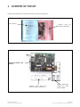
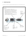
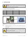
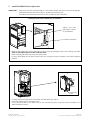
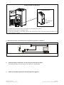
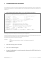
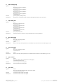
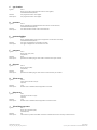
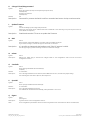
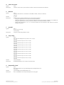
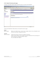
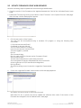
GE
Consumer & Industrial
Operating Manual
Digital Energy™
ADVANCED SNMP
WEB INTERFACE CARD
( for firmware version 1.84 or higher )
SG Series 10 - 500 / 400VAC CE / 480VAC UL
SitePro 10 - 500 kVA / 400VAC CE
SitePro A 10 - 300 kVA / 208-480VAC UL
LP 33 / 10, 20 & 30 kVA / 400VAC CE / Series 4
LP 33 / 10 & 20 kVA / 208VAC UL / Series 1
GE Consumer & Industrial SA
General Electric Company
CH – 6595 Riazzino (Locarno)
Switzerland
T +41 (0)91 / 850 51 51
F +41 (0)91 / 850 51 44
www.gedigitalenergy.com
Model
ADVANCED SNMP / WEB INTERFACE CARD
Date of issue:
01.02.2007
File name:
OPM_CNT_ADV_SNM_CRD_XGB_V050
Author:
Lorenzo Giuntini
Revision:
5.0
Identification No.
11701
Up-dating
Revision
3.1
4.0
5.0
Concerns
General review for UL and new layout
Without BNC, new layout and company name changes (GE)
Introduction of PMAD functionality
Date
15.06.2004
06.12.2004
12.12.2006
Table of contents
1
2
3
4
5
6
CONTENT OF THE KIT.........................................................................................................................................................................................3
INTRODUCTION ....................................................................................................................................................................................................4
SPECIFICATION .....................................................................................................................................................................................................5
INSTALLATION.......................................................................................................................................................................................................6
REMOVE ...................................................................................................................................................................................................................9
CONFIGURATION METHODS........................................................................................................................................................................ 10
6.1
6.2
7
8
SNMP AGENT.................................................................................................................................................................................................................. 17
WEB SERVER................................................................................................................................................................................................................... 17
8.2.1
8.2.2
8.2.3
8.2.4
8.2.5
8.2.6
8.2.7
8.2.8
8.2.9
Login and UPS Identification web page.............................................................................................................................................................................. 17
UPS Details web page.................................................................................................................................................................................................................. 20
UPS Alarms web page ................................................................................................................................................................................................................. 21
UPS Tests web page ..................................................................................................................................................................................................................... 22
UPS Control web page................................................................................................................................................................................................................. 24
UPS Configuration web page................................................................................................................................................................................................... 25
Agent Configuration web page............................................................................................................................................................................................... 26
Trap Configuration web page.................................................................................................................................................................................................. 27
Special Functions web page..................................................................................................................................................................................................... 28
UPDATE FIRMWARE......................................................................................................................................................................................... 29
9.1
9.2
10
11
CONFIGURATION OVER THE NETWORK ............................................................................................................................................................. 10
CONFIGURATION VIA A SERIAL CONNECTION................................................................................................................................................. 10
CONFIGURATION OPTIONS .......................................................................................................................................................................... 11
USE.......................................................................................................................................................................................................................... 17
8.1
8.2
9
Page
UPDATE FIRMWARE USING TELNET OR SERIAL LINE .................................................................................................................................... 29
UPDATE FIRMWARE USING WEB BROWSER..................................................................................................................................................... 30
SUPPORTED MIB VARIABLES ....................................................................................................................................................................... 31
SUPPORT .............................................................................................................................................................................................................. 32
COPYRIGHT © 2007 by GE Consumer & Industrial
All rights reserved; reproduction without permission prohibited.
This manual may be subject to change; no liability can be accepted for any error or omission.
Modifications reserved
OPM_CNT_ADV_SNM_CRD_XGB_V050.doc
Page 2/33
Operating Manual ADVANCED SNMP / WEB INTERFACE CARD
1 CONTENT OF THE KIT
The advanced SNMP Card is delivered with the following material:
User Manual
Special note for
SitePro installation
Advanced SNMP Card
IM0025
Smaller front panel for
SitePro and SG Series UPS
Modifications reserved
OPM_CNT_ADV_SNM_CRD_XGB_V050.doc
Square plates and
screws for older
SitePro UPS
Page 3/33
Operating Manual ADVANCED SNMP WEB INTERFACE CARD
2 INTRODUCTION
WARNING !
The work to be done is reserved to Service engineers which have been previously
trained on these UPS's, and therefore have thorough knowledge about the
function and handling of this equipment.
Introduction
The SNMP/Web Interface is designed to present information about the UPS on the network.
The interface provides the UPS information in two ways:
•
SNMP Agent
The SNMP information complies to the standard UPS-MIB which is defined in RFC1628.
Additional information are available with the GESingle and GEParallel MIB.
This format allows one or more NMSs (Network Management System) to monitor, manage and
control the UPS.
In addition, GE supports protection software and remote monitoring software using this information
to determine the status of the UPS and guarantee safe and orderly shutdown when necessary.
•
Web Server
The UPS information is also available in HTML format. HTML is the basic language for internet
communication. Every standard internet browser can be used to monitor and control the UPS using
HTML from anywhere on the network or even from anywhere in the world when using the internet.
ARCHITECTURE DIAGRAM
WIN
95
WIN
NT
Comport PC
(console)
UTP
Modifications reserved
Ethernet
NOTE:
only required for
configuration
1:1 RS232
OPM_CNT_ADV_SNM_CRD_XGB_V050.doc
UNIX
10/100 Mbits
Page 4/33
Operating Manual ADVANCED SNMP / WEB INTERFACE CARD
3 SPECIFICATION
Here follows a short description regarding the different plugs present on the frontal panel of the card:
Green Led
Indicate 4 different operating modes of the card:
1. When on and stable, it indicates that the card is
powered, but there is no communication with the UPS.
2. When blinking slow (1/sec.), it indicates that the card is
powered and there is communication with the UPS.
3. When blinking fast (6/sec.), it indicates the card is
updating the ROM and in this case, it is most important
not to reset or disconnect the card.
4. If the card is started in the restore mode, the led is
blinking corresponding to the SOS notification (...---...).
RJ45 Connector
Red Led
Used
to
communicate
with
10 or 100 Mbits
according to the
standard 10Base - T
or 100Base –TX.
Indicates
transmission
reception of
packets over
LAN bus.
Modifications reserved
OPM_CNT_ADV_SNM_CRD_XGB_V050.doc
RS232 Port
Used
only
to
configure
the
parameters of the
card (9600-N-8-1).
(see chapter 6).
Reset Button
the
and
the
the
For a complete
reset of the card.
Page 5/33
Operating Manual ADVANCED SNMP / WEB INTERFACE CARD
4 INSTALLATION
WARNING !
The work to be done is reserved to Service engineers which have been
previously trained on these UPS's, and therefore have thorough knowledge
about the function and handling of this equipment.
1
Check if the card has the correct logical address.
The logical address is installed trough the jumper JP5, JP6 in the following way:
Logical Address [dec]
Jumper 5
Jumper 6
84
Installed
Installed
SNMP Card 1
85
Installed
Not installed
SNMP Card 2
86
Not installed
Installed
SNMP Card 3
87
Not Installed
Not Installed
SNMP Card 0
(1)
(1) Default setup
Jumper 5
Jumper 6
IMPORTANT: Attention for correct direction of the jumpers.
NOTE:
- The setting of the jumper can be disabled with a specific configuration parameter (see
chapter 6, parameters “O”)
- The logical address is only important when more than one SNMP Card is installed on the
same UPS system.
NOTE !
Please refer to the “Safety Rules” included in the “Operating Manual” of the UPS.
Please read carefully the UPS “Operating Manual & installation Guide” before
installing or operating the equipment.
If any problems are encountered with the description of this installation guide,
please contact the nearest Service Centre before proceeding.
Modifications reserved
OPM_CNT_ADV_SNM_CRD_XGB_V050.doc
Page 6/33
Operating Manual ADVANCED SNMP / WEB INTERFACE CARD
2
Install the SNMP Card in option slot.
IMPORTANT:
Switch off the UPS, and wait approx. 2 minutes or switch the UPS to the manual bypass.
Please ensure that the mains input is reliable during this period.
All cables must be disconnected from the card during the installation.
Install procedure for LANPRO 33 / LP 33 Series
01
ctions_
ut prote
S witho
0_UP
LP33_3
Option slot (see
description below
for procedure)
Q1 Q2
Customer interface
F3
F1 F2
1. Remove the plate that covers the Option slot by cutting the edges which are holding the plate.
Take care the plate does not fall inside the UPS!
2. Slide carefully the SNMP Card into the Options slot.
3. Fix the frontal plate of the SNMP Card to the UPS, using the screw included in the SNMP Interface
Card kit.
Install procedure for SitePro S6
Connectivity box
SP_150-200_S6_customer interface_01
J11
XA
Q1 Q2 Q4
P4
SNMP
SNMP
CARD
PROTECTION
PLATE
1. Change the frontal plate with the smaller one delivered with the Kit.
2. Insert the SNMP Card in the options slot.
3. Fix the frontal plate of the SNMP Card to the connectivity box, using the screw included in the
SNMP Interface Card kit.
Modifications reserved
OPM_CNT_ADV_SNM_CRD_XGB_V050.doc
Page 7/33
Operating Manual ADVANCED SNMP WEB INTERFACE CARD
SGT5000_050-080_UPS_GE_03
Install procedure for SG Series
OFF
ON
OFF
ON
CNT_Customer Interface_01
Q1
Connectivity box
P4
Adv. SNMP Card
Q2
Protection
Plate
1. Change the frontal plate with the smaller one delivered with the Kit.
2. Insert the SNMP Card in the options slot.
3. Fix the frontal plate of the SNMP Card to the connectivity box, using the screw included in the
SNMP Interface Card kit.
3 Make all necessary connections (see architecture diagram in chapter 2)
4
Check that after a while (max. 30 sec.) the green led starts to blink.
This means that the communication with the UPS is established.
5
Switch on the UPS or go back to normal mode from bypass.
Modifications reserved
OPM_CNT_ADV_SNM_CRD_XGB_V050.doc
Page 8/33
Operating Manual ADVANCED SNMP WEB INTERFACE CARD
5 REMOVE
WARNING !
The work to be done is reserved to Service engineers which have been
previously trained on these UPS's, and therefore have thorough
knowledge about the function and handling of this equipment.
NOTE !
The installation and cabling of the option “Advanced SNMP/
WEB Interface” must be performed by QUALIFIED SERVICE
PERSON.
Please refer to the “Safety Rules” included in the “Operating Manual” of
the UPS.
Please read carefully the UPS “Operating Manual & installation Guide”
before installing or operating the equipment.
If any problems are encountered with the description of this installation
guide, please contact the nearest Service Centre before proceeding.
1
Switch off the UPS, and wait approx. 2 minutes or switch the UPS to the manual
bypass
Please ensure that the mains input is reliable during this period.
2
Remove all connections from the Advanced SNMP Card
3
Remove the Advanced SNMP Card from the slot
4
Switch on the UPS or go back to normal mode from bypass
Modifications reserved
OPM_CNT_ADV_SNM_CRD_XGB_V050.doc
Page 9/33
Operating Manual ADVANCED SNMP / WEB INTERFACE CARD
6 CONFIGURATION METHODS
Configuration of the SNMP Card can be done in two ways:
Via the network ( Chapter 6.1) or using a serial connected computer with a terminal emulation program (
Chapter 6.2).
For full configuration of the SNMP Card from the network, a BOOTP or DHCP Server must be available on
the network.
6.1 CONFIGURATION OVER THE NETWORK
The factory default way of retrieving an IP-address is by using DHCP.
On the card you will find a sticker with its MAC-address that needs to be configured in the BOOTP/DHCP
server.
After assigning the IP-address to this MAC-address in the BOOTP/DHCP Server the card needs to be
rebooted to retrieve this IP-address.
For a reboot press the reset button on the card.
NOTE:
the SNMP Card recognizes a BOOTP-reply from the server only when this latter uses broadcast
addressing for the destination on both the MAC and the IP address fields.
Configuration of the other parameters can be performed using either a telnet program or a Webbrowser.
The default loginname and password are both ‘GE’.
After having passed the login info the configuration screen will appear.
For security reasons we suggest to change the default loginname and password immediately!
Please proceed with Chapter 7 (Telnet) or Chapter 8.2 (Web Browser).
6.2 CONFIGURATION VIA A SERIAL CONNECTION
Connect the SNMP Card to the computer using a standard 1:1 serial cable.
Run a terminal simulator like Windows Terminal or Hyperterminal.
Configure your terminal simulator as follows:
9600 bps, 8 data bits, 1 stop bit, none parity check, none flow control.
Terminal emulation: VT-100
Establish a connection and press <x>.
The configuration screen will appear. Please proceed with Chapter 7.
Modifications reserved
OPM_CNT_ADV_SNM_CRD_XGB_V050.doc
Page 10/33
Operating Manual ADVANCED SNMP / WEB INTERFACE CARD
7 CONFIGURATION OPTIONS
The configuration screens of the telnet method and serial method are identical, while the configuration
screens of the web server is a somewhat different (for more details about the web server please refer to
Chapter 6.2).
1
After having executed the steps in either 6.1 or 6.2 the following screen appears
---<<Current config>>---<<Code vY.YY bZ.ZZ>>---[-]---[MAC=XX:XX:XX:XX:XX:XX]--[IP=0.0.0.0] [mask=255.255.255.0] [gateway=0.0.0.0]
----------------------------------------------------------------------------1. boot-method
= [dhcp]
R. clear reset count [0]
2. ip-address
= [0.0.0.0]
T. ping
3. subnet mask
= [255.255.255.0]
U. trap config
4. gateway
= [0.0.0.0]
V. responsible e-mail
5. trap addresses = [0.0.0.0] [0.0.0.0] [0.0.0.0] [0.0.0.0]
6. trap community = [public] [public] [public] [public]
7. trap UDP port = [162] [162] [162] [162]
8. get-community = [public]
9. set-community = [public]
A. sys-contact
= [The contact person for this agent]
B. sys-name
= [The administrative name of the agent]
C. sys-location
= [The physical location of the agent]
D. upsName
= [The administrative name of the connected UPS]
E. upsAttachedDev = [The type of equipment connected to the UPS]
F. snmpport
= [161]
H. telnet server = [on]
G. httpport
= [80]
I. http server
= [on]
J. telnet/http username = [GE]
K. change telnet/http password
L. update firmware
M. MAC
N. reboot
O. cardaddr = [0]
P. upsaddr = [0]
Q. logout
S. ethernet = [Auto]
GE>
The settings shown are the settings of the currently active configuration.
Using the Telnet/Serial menu you can enter the necessary values in each field by typing the menu item
number/character and then type the value of the selected parameters
Also partial names which are unique are accepted:
Examples:
GE> 1
Choose boot-method (0=dhcp, 1=bootp, 2=configured ip/mask/gw) [2]:
0 [Enter]
GE>
2
Enter the necessary value in each field
3
Press <N> to reboot the agent
4
In case of configuration via a serial connection disconnect the RS232 cable from the
SNMP Interface Card
Modifications reserved
OPM_CNT_ADV_SNM_CRD_XGB_V050.doc
Page 11/33
Operating Manual ADVANCED SNMP / WEB INTERFACE CARD
Explanation of configuration parameters
Please note: All changes to the configuration will be effective only after having executed a reboot
command (“N”).
1.
boot-method
Syntax:
GE> 1
Choose boot-method (0=dhcp, 1=bootp, 2=configured ip/mask/gw) [0]
X [Enter]
Default:
Parameters:
0 (dhcp)
0 = dhcp -> The card obtains its dynamic IP-address from a DHCP server.
1 = bootp -> The card obtains its static IP-address from the BOOTP server.
2 = configured ip/mask/gw -> The card uses a static IP-address configured in its ROM (Parameters 2,3 and 4,
which follows).
Description:
Defines the way the SNMP plug in card boots and links itself up to the network.
2.
ip-address
Syntax:
GE> 2
Enter card ip [0.0.0.0]:
XXX.XXX.XXX.XXX [Enter]
Default:
0.0.0.0
Description:
The static IP-address of the SNMP plug in card.
Note: If BOOTP/ DHCP is used this value is ignored.
3.
submask mask
Syntax:
GE> 3
Enter netmask [255.255.255.0]:
XXX.XXX.XXX.XXX [Enter]
Default:
Description:
255.255.255.0
The subnet the SNMP plug in card is situated in.
Note: If BOOTP/DHCP is used AND the BOOTP/DHCP server provides the subnet mask, this value is ignored.
4.
gateway
Syntax:
GE> 4
Enter gateway [0.0.0.0]:
XXX.XXX.XXX.XXX [Enter]
Default:
Description:
0.0.0.0
The IP-address of the default gateway (default router).
Note: If BOOTP/DHCP boot-method is used AND the BOOTP/DHCP server provides the IP-address to the
default gateway this value is ignored.
5.
traps addresses
Syntax:
Default:
Description:
GE> 5
Enter trap 1 ip [0.0.0.0]:
XXX.XXX.XXX.XXX [Enter]
Enter trap 2 ip [0.0.0.0]:
XXX.XXX.XXX.XXX [Enter]
Enter trap 3 ip [0.0.0.0]:
XXX.XXX.XXX.XXX [Enter]
Enter trap 4 ip [0.0.0.0]:
XXX.XXX.XXX.XXX [Enter]
[0.0.0.0] [0.0.0.0] [0.0.0.0] [0.0.0.0]
Specifies the destination IP-addresses of Network Management Stations traps have to be sent to.
A maximum of 4 trap addresses can be defined.
To disable a trap, specify [0.0.0.0] as address.
Modifications reserved
OPM_CNT_ADV_SNM_CRD_XGB_V050.doc
Page 12/33
Operating Manual ADVANCED SNMP WEB INTERFACE CARD
6.
traps community
Syntax:
GE> 6
Enter trap 1 community [public]:
XXXXXXX [Enter]
Enter trap 2 community [public]:
XXXXXXX [Enter]
Enter trap 3 community [public]:
XXXXXXX [Enter]
Enter trap 4 community [public]:
XXXXXXX [Enter]
Default:
Description:
[public] [public] [public] [public]
Specifies the community names of Network Management Stations traps are sent to.
7.
traps UDP port
Syntax:
Default :
GE> 7
Enter trap 1 UDP port [162]:
XXXXXXX [Enter]
Enter trap 2 UDP port [162]:
XXXXXXX [Enter]
Enter trap 3 UDP port [162]:
XXXXXXX [Enter]
Enter trap 4 UDP port [162]:
XXXXXXX [Enter]
[162] [162] [162] [162]
Description:
Assign the UDP port-number to every trap destination previously defined.
8.
get-community
Syntax:
Default:
Description:
9.
GE>8
Enter get-community [public]:
XXXXXXX [Enter]
public
SNMP community name (password) to read SNMP UPS information from the SNMP plug in card.
set-community
Syntax:
Default:
GE> 9
Enter set-community [public]:
XXXXXXX [Enter]
public
Description:
SNMP community name (password) to write SNMP UPS information to the SNMP plug in card.
A.
sys-contact
Syntax:
Default:
Description:
B.
GE> A
Enter sys-contact [The contact person for this agent]:
XXXXXXXXXXXXXXX [Enter]
The contact person for this agent
The contact person for this agent
sys-name
Syntax:
GE> B
Enter sys-name [The administrative name of the agent]:
XXXXXXXXXXXXXXX [Enter]
Default:
Description:
The administrative name of the agent
The administrative name of the agent
Modifications reserved
OPM_CNT_ADV_SNM_CRD_XGB_V050.doc
Page 13/33
Operating Manual ADVANCED SNMP WEB INTERFACE CARD
C.
sys-location
Syntax:
GE> C
Enter sys-location [The physical location of the agent]:
XXXXXXXXXXXXXXX [Enter]
Default:
The physical location of the agent
Description:
The physical location of the agent
D.
upsName
Syntax:
Default:
Description:
E.
upsAttachedDev
Syntax:
Default:
Description:
F.
Default:
Description:
Default:
Description:
Default:
Description:
GE> H
Telnet server (0=off 1=on) [1]:
X [Enter]
1=on
Enables (on) or disables (off) configuration via telnet.
Http server
Syntax:
Default:
Description:
J.
GE> G
Enter http port [80]:
XXX [Enter]
[80]
Specifies the SNMP plug in card’s HTTP communication port number.
Telnet server
Syntax:
I.
GE> F
Enter snmp port [161]:
XXX [Enter]
[161]
Specifies the SNMP plug in card’s UDP communication port number.
httpport
Syntax:
H.
GE> E
Enter upsAttachedDev [The type of equipment connected to the UPS]:
XXXXXXXXXXXXXXX [Enter]
The type of equipment connected to the UPS
The type of equipment connected to the UPS
snmpport
Syntax:
G.
GE> D
Enter upsName [The administrative name of the connected UPS]:
XXXXXXXXXXXXXXX [Enter]
The administrative name of the connected UPS
The administrative name of the connected UPS
GE> I
Http server (0=off 1=on) [1]:
X [Enter]
1=on
Enables (on) or disables (off) configuration via web browser.
Telnet/Http username
Syntax:
Default:
Description:
GE> J
Enter new username [GE]:
XXXXX [Enter]
GE
Username for protects the SNMP card from unauthorised access via http or telnet session.
Modifications reserved
OPM_CNT_ADV_SNM_CRD_XGB_V050.doc
Page 14/33
Operating Manual ADVANCED SNMP WEB INTERFACE CARD
K.
Change Telnet/Http password
Syntax:
Default:
GE> K
Enter new passwd [to keep current passwd just press enter]:
XXXXX [Enter]
Re-enter new passwd:
XXXXX [Enter]
GE
Description:
Password for protects the SNMP card from unauthorised access via http or telnet session.
L.
Update firmware
Syntax:
GE> L
FTP Server Ready. Ftp the image and press Enter.
[When the new release of the software has been transferred to the card using FTP protocol press Enter. For
more details see chapter 5]
Description:
Enable and start the FTP server to update the firmware.
M. MAC
Syntax:
GE> M
Each card has unique MAC address. This value may be changed only by GE.
If you need to change it, contact GE support. Press Enter to continue.
Description:
It is possible to change the MAC address only if the GE support is called.
The GE support give you the necessary instruction to make this change.
N.
reboot
Syntax:
Description:
O.
GE> N
Reboots the SNMP plug to activate the changes made to the configuration and exit from the current
configuration session.
CardAddr
Syntax:
GE> O
Enter card logical address (0=autoselect) [0]:
XX [Enter]
Default:
Description:
0 = autoselect
This is the logical address of the card and, when different from zero, overrides the jumper setting.
The valid range for this value is [84...87]. See Chapter 4.1.
P.
UpsAddr
Syntax:
Default :
Description:
Q.
GE> P
Enter ups logical address (0=autoselect) [0]:
0 = autoselect
This is the logical address of the UPS.
This address can be detected automatically if this parameter is set to zero.
logout
Syntax:
Description:
Note:
GE>Q
Quit (log out)
Logout from the current configuration session.
Some configuration parameters can be lost when they haven’t been stored with the reboot command (“N”).
Modifications reserved
OPM_CNT_ADV_SNM_CRD_XGB_V050.doc
Page 15/33
Operating Manual ADVANCED SNMP WEB INTERFACE CARD
R.
Clear reset count
Syntax:
GE>R
Description:
Clear the reset counter, which holds the number of times the board has been resettled.
S.
Ethernet
Syntax:
GE> S
Ethernet mode (0=Auto, 1=10/100TP, 2=10TP/BNC, 3=BNC, 4=100TP, 5=10TP) [0]:
X [Enter]
Default:
Description:
0 = Auto
Defines how the board should detect the correct Ethernet interface.
- Setting this parameters to zero (0), forces a full auto detection
- Setting this parameters to one (1), restricts the detection to the RJ45 connector (10 BASE-T or 100 BASE-TX)
- Setting this parameters to two (2), restricts the detection to 10 Mbits (10 BASE-T or BNC)
- Setting these parameters to 3, 4 or 5 the board refrains from auto detection and imposes the specific
interface and speed.
T.
UpsAddr
Syntax:
Description:
U.
GE> T
Enter IP of host to ping:
X.X.X.X [Enter]
Ping the corresponding address TCP/IP.
Trap Config
Syntax:
GE>U
RFC traps (sent always from ups 0) (0 = off 1 = on) [0] :
X [Enter]
GE Traps sent from ups 0 (0 = off 1 = on) [0] :
X [Enter]
GE Traps sent from ups 1 (0 = off 1 = on) [0] :
X [Enter]
GE Traps sent from ups 2 (0 = off 1 = on) [0] :
X [Enter]
GE Traps sent from ups 3 (0 = off 1 = on) [0] :
X [Enter]
GE Traps sent from ups 4 (0 = off 1 = on) [0] :
X [Enter]
GE Traps sent from ups 5 (0 = off 1 = on) [0] :
X [Enter]
GE Traps sent from ups 6 (0 = off 1 = on) [0] :
X [Enter]
GE Traps sent from ups 7 (0 = off 1 = on) [0] :
X [Enter]
GE Traps sent from ups 8 (0 = off 1 = on) [0] :
X [Enter]
Default:
Description:
all traps disabled
Enabled/Disabled the sent of trap for a specified UPS.
V.
Responsible E-Mail
Syntax:
Default:
GE>V
Enter responsible e-mail : [[email protected]]:
XYZ [Enter]
[email protected]
Description:
The e-mail address of the responsible person for this agent.
Modifications reserved
OPM_CNT_ADV_SNM_CRD_XGB_V050.doc
Page 16/33
Operating Manual ADVANCED SNMP WEB INTERFACE CARD
8 USE
8.1 SNMP AGENT
The SNMP agent can be used for two applications:
•
NMS (Network Management Software)
The card allows you to monitor a UPS with any NMS (eg. Tivoli, HP-Openview or CA Unicenter) to
detect and react on any status change of the UPS.
For this type of application the card needs to be configured to send traps to the computer on which
the NMS runs.
Up to four different trap addresses are configurable.
•
Protection software
Besides from monitoring a locally connected UPS, protection software can also monitor the status
of a UPS via the network when it has an SNMP agent installed.
This creates the ability to configure very flexible protection schemes.
A typical example is an application server, which is depending on a database server.
The protection software on the application server will detect a power failure on the database server
and will start to close all database connections before the database server shuts itself down.
8.2 WEB SERVER
The built-in web server functionality enables the user to monitor and control the UPS using a standard
internet browser.
The offered information of the web server gives a complete and detailed status overview in a very user
friendly way.
Besides, measurement values of the UPS and complete configuration can be done via the web browser.
8.2.1 Login and Identification web page
To establish a connection with the Web Interface of the SNMP Interface Card, open your web browser
and enter the TCP/IP address of the card in the address line of your browser.
If the connection is established successfully, a screen very similar to the one below, will appear:
To see the details of the UPS, click in the “Login” button and enter the user login-name and password.
Modifications reserved
OPM_CNT_ADV_SNM_CRD_XGB_V050.doc
Page 17/33
Operating Manual ADVANCED SNMP / WEB INTERFACE CARD
The default login-name and password are both ‘GE’.
For security reasons we suggest to change the default loginname and password immediately!
After having passed the login info, the “Identification” web page will appear.
The page that appears will show some basic information regarding the UPS and the SNMP Interface
Card.
Depending on the actual UPS model, version and configuration, some features may be unsupported, or
some values may not be displayed. In these cases, the parameter/value may be shown as ‘n/a’ or ‘not
available’. Particularly, in a parallel system, the identification data for the single UPSs will not include the
System Group section.
Networks Setting
IP address:
Subnet mask:
Default gateway:
Identification group
Manufacturer:
Model:
Serial:
UPS Software Agent:
Agent Software Version:
UPS Name:
Attached Device:
Responsible E-Mail:
System Group
SysDescription:
SysUpTime:
SysContact:
SysName:
SysLocation:
Modifications reserved
OPM_CNT_ADV_SNM_CRD_XGB_V050.doc
The static IP-address of the SNMP plug in card.
The subnet the SNMP plug in card is situated in.
The IP-address of the default gateway (default router).
The name of the UPS manufacturer.
The UPS Model designation.
The serial number of the UPS.
The UPS firmware/software version(s).
The UPS agent software version.
The administrative name of the connected UPS
The type of equipment connected to the UPS
The E-Mail address of the responsible person for this agent.
A textual description of the entity. This value should include the full name and version
identification of the system's hardware type, software operating-system, and
networking software."
The time since the network management portion of the system was last re-initialized.
The contact person for this agent
The administrative name of the agent
The physical location of the agent
Page 18/33
Operating Manual ADVANCED SNMP WEB INTERFACE CARD
WARNING !
Every time a change is made, remember to click onto the appropriate
“Apply” button to confirm the change.
Contrary if this “Apply” button has not been clicked, the change has no
effect and when the web page is reloaded the old value appears.
If, after having confirmed the change, a error pop-up appears, means
that the UPS cannot accept this change at all, or perform this change
at this moment.
The Web Interface includes different web pages. The menu frame on the left-hand side of the page
provides links to the various pages. It is a dynamic menu, which is automatically configured depending
on the UPS configuration. The sub-items under a header can be shown/hidden by clicking on the
header. In case of a stand-alone single UPS configuration, the menu will include the following entries:
• UPS [header]
o Identification
[page link]
o Details
[page link]
o Alarms
[page link]
o PMAD
[page link]
o Test
[page link]
o Control
[page link]
o Configuration
[page link]
• Agent Configuration
[page link]
• Trap Configuration
[page link]
• Special functions
[page link]
In case of a parallel configuration, both the overall (System) values and the single UPS values are
available. However, some controls (‘Test’, ‘Control’ and ‘Configuration’ pages) are not available at a
System level.
In a parallel configuration, the top-right corner of the web page will show whether the displayed values
apply to the System or to single UPSs.
The various pages include the following information:
Identification:
Gives some basis information regarding the UPS and the SNMP Interface
Card
Details:
Shows all details regarding the UPS (battery voltage, input voltage,…)
Alarms:
Shows the alarms (Events) of the UPS
PMAD:
Shows advanced diagnostic information
Tests:
Give the possibility to make some events in the UPS
Control:
Shows or changes the parameters regarding the shutdown
Configuration:
Shows or changes the parameters regarding the configuration of the
battery, input, ….
Agent Configuration:
Shows or changes the parameters regarding the configuration of the
agent (TCP/IP, submask, …).
Trap Configuration:
Shows or changes the parameters regarding the configuration of the
trap (TCP/IP trap, Trap UDP port, enabled/disabled trap, …)
Special Function:
Offers the possibility to reboot or upgrade the firmware of the agent
Modifications reserved
OPM_CNT_ADV_SNM_CRD_XGB_V050.doc
Page 19/33
Operating Manual ADVANCED SNMP WEB INTERFACE CARD
8.2.2 Details web page
Clicking in the “Details” page link, a similar screen will appear:
Meaning of the different fields present at the UPS Details page:
Battery Group
Battery Status:
Second On battery:
EstimatedMinuteRemain:
EstimatedChargeRemain:
Battery voltage:
Battery current:
Battery temperature:
Battery ripple:
Input Group
Phase:
Frequency:
Voltage:
Current:
True Power:
Bad Input Line:
Output Group
Phase:
Voltage:
Current:
Power:
Load:
Power Factor:
Peak Current:
Share Current:
Output Source:
Output frequency:
Indication of the remaining capacity in the UPS system's batteries. A value of battery Normal indicates
that the remaining run-time is greater than LowBattTime (see UPS configuration page). A value of battery
Low indicates that the remaining battery run-time is less than or equal to Low BattTime (see UPS
configuration page). A value of battery Depleted indicates that the UPS will be unable to sustain the
present load when and if the utility power is lost (including the possibility that the utility power is
currently absent and the UPS is unable to sustain the output).
If the unit is on battery power, the elapsed time since the UPS last switched to battery power, or the time
since the network management subsystem was last restarted, whichever is less.
Zero shall be returned if the unit is not on battery power.
An estimate of the time to battery charge depletion under the present load conditions if the utility power
is off and remains off, or if it were to be lost and remains off.
An estimate of the battery charge remaining, expressed as a percent of full charge.
The value of the present battery voltage.
The present battery current.
The ambient temperature at or the temperature close to the UPS Battery.
The present DC link RMS voltage ripple.
The input line identifier.
The present input frequency.
The magnitude of the present input voltage.
The magnitude of the present input current.
The magnitude of the present input true power.
A count of the number of times the input entered an out-of-tolerance condition as defined by the
manufacturer. This count is incremented by one each time the input transitions from zero out-oftolerance lines to one or more input lines out-of-tolerance.
The output line identifier.
The magnitude of the present output voltage.
The magnitude of the present output current.
The present output true power.
The percentage of the UPS power capacity presently being used on this output line.
The present output power factor. A positive value indicate an inductive load; a negative value indicate a
capacitive load; value 1 indicate a resistive load.
Note: the value may not be available in case of low UPS load.
The present output peak current..
The present share component of the inverter output current into a parallel system; RMS value.
The present source of output power. The enumeration none indicates that there is no source of output
power (and therefore no output power), for example, the system has opened the output breaker.
The present output frequency.
Bypass Group
Phase:
Voltage:
Current:
Power:
Bypass Frequency:
The bypass line identifier.
The present bypass voltage.
The present bypass current.
The present true power conveyed by the bypass.
The present bypass frequency.
Modifications reserved
OPM_CNT_ADV_SNM_CRD_XGB_V050.doc
Page 20/33
Operating Manual ADVANCED SNMP WEB INTERFACE CARD
8.2.3 Alarms web page
Clicking on the “Alarms” page link a similar screen will appear:
Meaning of the different fields shown on the UPS Alarms page:
Alarm Group
Alarm present:
The present number of active alarm conditions.
Communication:
The state of the communication with the UPS and the SNMP Interface Card.
If this field is “ok” the card is communicating with the UPS, contrary with “failed”
there is no communication between SNMP Interface Card and UPS.
Alarm ID:
The name of the present alarm. When the box is red the alarm is activated,
contrary when its white the alarm is inactive.
The grey colours of the box means that this alarm is not supported by the UPS
Duration:
The time passed since the alarm has been activated.
Modifications reserved
OPM_CNT_ADV_SNM_CRD_XGB_V050.doc
Page 21/33
Operating Manual ADVANCED SNMP WEB INTERFACE CARD
8.2.4 PMAD web page
Clicking on the “PMAD” page link a similar screen will appear:
Meaning of the different fields shown on the UPS Alarms page:
Lifetime
Global Service Check:
Battery:
DC Capacitors:
AC Capacitors:
Fans:
Main statistics
Mains bypass failures:
Mains rectifier failure:
Transients on the main bypass:
Bypass reliability degree:
Bus communication
Qty of UPSs:
Channel table:
The remaining time (in [Weeks:Days]) before a general service check.
The remaining time (in [Weeks:Days]) before a battery check.
The remaining time (in [Weeks:Days]) before a DC capacitors check
The remaining time (in [Weeks:Days]) before an AC output filter capacitors check
The remaining time (in [Weeks:Days]) before a fan check
Count of main bypass failures (>200 ms), since UPS installation.
Count of mains rectifier failures (>200 ms), since UPS installation.
Count of transients on the mains bypass (X..Y ms), during the last 7 days
Bypass reliability degree [0..100%]
Number of UPSs as currently seen in the parallel system.
The reset button forces a refresh of the count and the display.
The table shows the actual communication status over the two redundant buses
between the unit currently selected (in green bold) and other units.
Note: The ‘Bus communication section’ is only available for single UPSs in a parallel configuration. It is
not available for stand-alone UPSs, or for the System in a parallel configuration.
Modifications reserved
OPM_CNT_ADV_SNM_CRD_XGB_V050.doc
Page 22/33
Operating Manual ADVANCED SNMP WEB INTERFACE CARD
8.2.5 Test web page
Clicking on the “Test” page link a similar screen will appear:
Meaning of the different fields shown at the UPS Tests page:
Test Group
Test ID:
Shows the name of the test in progress if a test is in progress or the name of the last test
performed, if no test is in progress, unless no test has been run, in which case the value
NoTestsInitiated is returned.
Test Result
Summary:
The results of the current, or last UPS diagnostics test performed.
The values for donePass,doneWarning, and doneError indicate that the test was completed
either successfully, with a warning, or with an error, respectively.
The value aborted is returned for tests which are aborted by setting the value TestInit to
AbortTestInProgress.
Tests which have not yet concluded are indicated by inProgress.
The value noTestsInitiated indicates that no previous test results are available, such as is
the case when no tests have been run since the last reinitialization of the network
management subsystem and the system has no provision for non-volatile storage of test
results.
Test Init:
Gives the possibility to choose between four different actions that the UPS could perform:
A test sufficient, to determine if the battery needs replacement.
QuickBatteryTest:
The test in progress has to be aborted.
Abort Test In Progress:
The manufacturer's standard test of UPS device systems.
GeneralSystemTest:
DeepBatteryCalibration: The system is placed on battery to a discharge level, set by the
manufacturer, sufficient to determine battery replacement and
battery run-time with a high degree of confidence.
WARNING:
this test will leave the battery in a low charge state and will require time
for recharging to a level sufficient to provide normal battery duration for
the protected load.
NOTE:
Only after clicking in the “Apply” button the UPS starts to perform the
action.
Modifications reserved
OPM_CNT_ADV_SNM_CRD_XGB_V050.doc
Page 23/33
Operating Manual ADVANCED SNMP WEB INTERFACE CARD
8.2.6 Control web page
Clicking on the “Control” page link a similar screen appears:
Meaning of the different fields present at the UPS Tests page:
Control Group
Shutdown After Delay:
Startup After Delay:
Reboot with Duration:
Shutdown Type:
Auto Restart:
Setting this object will shutdown (i.e., turn off) either the UPS output or the UPS system (as
determined by the value of ShutdownType at the time of shutdown) after the indicated number of
seconds, or less if the UPS batteries become depleted. Setting this object to 0 will cause the
shutdown to occur immediately. Setting this object to -1 will abort the countdown. If the system is
already in the desired state at the time the countdown reaches 0, then nothing will happen. That is,
there is no additional action at that time if upsShutdownType = system and the system is already off.
Similarly, there is no additional action at that time if upsShutdownType = output and the output is
already off. When the page is refreshed, the ShutdownAfterDelay will return the number of seconds
remaining until shutdown, or -1 if no shutdown countdown is in effect.
Sets to this object overrides any ShutdownAfterDelay already in effect.
Setting this object will start the output after the indicated number of seconds, including starting the
UPS, if necessary. Setting this object to 0 will cause the startup to occur immediately. Setting this
object to -1 will abort the countdown. If the output is already on at the time the countdown reaches
0, then nothing will happen. Settings to this object override the effect of any StartupAfterDelay
countdown or RebootWithDuration countdown in progress. When the page is refreshed,
StartupAfterDelay will return the number of seconds until startup, or -1 if no startup countdown is in
effect. If the countdown expires during a utility failure, the startup shall not occur until the utility
power is restored.
Setting this object will immediately shutdown (i.e.,turn off) either the UPS output or the UPS system
(as determined by the value of ShutdownType at the time of shutdown) for a period equal to the
indicated number of seconds, after which time the output will be started, including starting the UPS, if
necessary. If the number of seconds required to perform the request is greater than the requested
duration, then the requested shutdown and startup cycle shall be performed in the minimum time
possible, but in no case shall this require more than the requested duration plus 60 seconds. When
the page is refreshed, RebootWithDuration shall return the number of seconds remaining in the
countdown, or -1 if no countdown is in progress. If the startup should occur during a utility failure,
the startup shall not occur until the utility power is restored.
This object determines the nature of the action to be taken at the time when the countdown of the
ShutdownAfterDelay and RebootWithDuration objects reaches zero.
Setting this object to output indicates that shutdown requests should cause only the output of the
UPS to turn off. Setting this object to system indicates that shutdown requests will cause the entire
UPS system to turn off.
Setting this object to 'on' will cause the UPS system to restart after a shutdown if the shutdown
occurred during a power loss as a result of either a ShutdownAfterDelay or an internal battery
depleted condition. Setting this object to 'off' will prevent the UPS system from restarting after a
shutdown until an operator manually or remotely explicitly restarts it. If the UPS is in a startup or
reboot countdown, then the UPS will not restart until that delay has been satisfied.
Modifications reserved
OPM_CNT_ADV_SNM_CRD_XGB_V050.doc
Page 24/33
Operating Manual ADVANCED SNMP WEB INTERFACE CARD
8.2.7
Configuration web page
Clicking on the “Configuration” page link a similar screen appears:
Meaning of the different fields present at the UPS Configuration page:
Configuration Group
Input Voltage:
The magnitude of the nominal input voltage.
Input Frequency:
The nominal input frequency.
Output Voltage:
The magnitude of the nominal output voltage.
Output Frequency:
The nominal output frequency.
Low Battery Time:
The value of EstimatedMinutesRemaining (see page “UPS Details”) at which a
lowBattery condition is declared.
Low Voltage Transfer
Point:
The minimum input line voltage allowed before the UPS system transfers to battery
backup.
High Voltage Transfer
Point:
The maximum line voltage allowed before the UPS system transfers to battery
backup.
Audible Status:
The requested state of the audible alarm.
When in the disabled state, the audible alarm should never sound.
The enabled state is self-describing.
Setting this object to muted when the audible alarm is sounding shall temporarily
silence the alarm. It will remain muted until it would normally stop sounding and the
value returned for read operations during this period shall equal muted.
At the end of this period, the value shall revert to enabled.
Writes of the value muted when the audible alarm is not sounding shall be accepted
but otherwise shall have no effect.
Output VA:
The magnitude of the nominal VA rating.
Output Power:
The magnitude of the nominal true power rating.
Modifications reserved
OPM_CNT_ADV_SNM_CRD_XGB_V050.doc
Page 25/33
Operating Manual ADVANCED SNMP WEB INTERFACE CARD
8.2.8 Agent Configuration web page
Clicking on the “Agent Configuration” page link a similar screen appears:
Meaning of the different fields present at the Agent Configuration page:
Agent Configuration
Boot-Method:
Defines the way the SNMP plug in card boots and links itself up to the network.
dhcp -> The card obtains its dynamic IP-address from a DHCP server.
bootp -> The card obtains its static IP-address from the BOOTP server.
configured ip/mask/gw -> The card uses a static IP-address configured in its ROM.
IP Address:
The static IP-address of the SNMP plug in card.
Note: If BOOTP/ DHCP is used this value is ignored.
SubMask:
The subnet the SNMP plug in card is situated in.
Note: If BOOTP/DHCP is used AND the BOOTP/DHCP server provides the subnet mask, this value is ignored.
Gateway:
The IP-address of the default gateway (default router).
Note: If BOOTP/DHCP boot-method is used AND the BOOTP/DHCP server provides the IP-address to the
default gateway this value is ignored.
Get Community:
SNMP community name (password) to read SNMP UPS information from the SNMP plug in card.
Set Community:
SNMP community name (password) to write SNMP UPS information to the SNMP plug in card.
SNMP-port:
Specifies the SNMP plug in card’s UDP communication port number.
Telnet-Server:
Enables (on) or disables (off) configuration via telnet.
HTTP-Server:
Enables (on) or disables (off) configuration via web browser.
HTTP-port:
Specifies the SNMP plug in card’s HTTP communication port number.
Telnet/http-Username:
Username to protect the SNMP card from unauthorised access via http or telnet session.
Telnet/http -Password:
Password to protect the SNMP card from unauthorised access via http or telnet session.
UPS-Address:
This is the logical address of the UPS. This address can be detected automatically if this parameter is set to
zero.
Card-Address:
This is the logical address of the card and, when different from zero, overrides the jumper setting. The valid
range for this value is [84...87].
Ethernet-Config:
Defines how the board should detect the correct Ethernet interface.
- Setting this parameters to “Auto”, forces a full autodetection.
- Setting this parameters to “10/100TP”, restricts the detection to the RJ45 connector (10 BASE-T or 100
BASE-TX).
- Setting this parameters to “10 TP/BNC”, restricts the detection to 10 Mbits (10 BASE-T or BNC).
- Setting this parameters to BNC,100TP or 10TP the board refrains from autodetection and imposes the
specific interface and speed.
Modifications reserved
OPM_CNT_ADV_SNM_CRD_XGB_V050.doc
Page 26/33
Operating Manual ADVANCED SNMP WEB INTERFACE CARD
8.2.9 Trap Configuration web page
Clicking on the “Trap Configuration” page link a similar screen appears:
Meaning of the different fields present at the Trap Configuration page:
Trap Configuration
Trap 1:
Specifies the destination IP-address of Network Management Stations trap 1 has to be
sent to. To disable the trap specify [0.0.0.0] as address.
Trap 2:
Specifies the destination IP-address of Network Management Stations trap 2 has to be
sent to. To disable the trap specify [0.0.0.0] as address.
Trap 3:
Specifies the destination IP-address of Network Management Stations trap 3 has to be
sent to. To disable the trap specify [0.0.0.0] as address.
Trap 4:
Specifies the destination IP-address of Network Management Stations trap 4 has to be
sent to. To disable the trap specify [0.0.0.0] as address.
Trap 1 Community:
Specifies the community name of Network Management Stations trap 1 is sent to.
Trap 2 Community:
Specifies the community name of Network Management Stations trap 2 is sent to.
Trap 3 Community:
Specifies the community name of Network Management Stations trap 3 is sent to.
Trap 4 Community:
Specifies the community name of Network Management Stations trap 4 is sent to.
Trap 1 UDP Port:
The UDP port-number for the trap destination 1 previously defined.
Trap 2 UDP Port:
The UDP port-number for the trap destination 2 previously defined.
Trap 3 UDP Port:
The UDP port-number for the trap destination 3 previously defined.
Trap 4 UDP Port:
The UDP port-number for the trap destination 4 previously defined.
RFC Traps UPS 0:
Enabled/Disabled the sent of RFC trap for the UPS 0.
GE Traps UPS 0:
Enabled/Disabled the sent of GE trap for the UPS 0.
GE Traps UPS 1:
Enabled/Disabled the sent of GE trap for the UPS 1.
GE Traps UPS 2:
Enabled/Disabled the sent of GE trap for the UPS 2.
GE Traps UPS 3:
Enabled/Disabled the sent of GE trap for the UPS 3.
GE Traps UPS 4:
Enabled/Disabled the sent of GE trap for the UPS 4.
GE Traps UPS 5:
Enabled/Disabled the sent of GE trap for the UPS 5.
GE Traps UPS 6:
Enabled/Disabled the sent of GE trap for the UPS 6.
GE Traps UPS 7:
Enabled/Disabled the sent of GE trap for the UPS 7.
GE Traps UPS 8:
Enabled/Disabled the sent of GE trap for the UPS 8.
Modifications reserved
OPM_CNT_ADV_SNM_CRD_XGB_V050.doc
Page 27/33
Operating Manual ADVANCED SNMP WEB INTERFACE CARD
8.2.10 Special Functions web page
Clicking in the header identifier page “Special Functions” a similar screen appears:
Meaning of the different fields present at the Special Functions page:
Reboot
Reboot Agent:
Reboots the SNMP plug to activate the changes made to the configuration and
exit from the current configuration session.
Upgrade
Start FTP Server:
Enable and start the FTP server to update the firmware.
When the new release of the software has been transferred to the card using FTP
protocol press the “Upgrade firmware “ button.
For more details see Chapter 7.
Modifications reserved
OPM_CNT_ADV_SNM_CRD_XGB_V050.doc
Page 28/33
Operating Manual ADVANCED SNMP WEB INTERFACE CARD
9 UPDATE FIRMWARE
The SNMP card gives the possibility to update the firmware via LAN using a FTP server.
9.1 UPDATE FIRMWARE USING TELNET OR SERIAL LINE
Here, the necessary steps to update the firmware using Telnet or serial line:
1.
Check the version of the firmware at the top of the setup menu (vZ.ZZ = firmware version, bX.XX
backup version):
--<<Current config>>----<<Code vZ.ZZ bX.XX>>----[MAC=00:50:c2:09:70:02]-----------
2.
Enable the FTP server typing the key “L” in the setup menu
GE> L
FTP Server Ready. Ftp the image and press Enter.
3. FTP the new version of the firmare.
This step can be accomplished using a windows FTP program or using DOS commands as follows:
C:\>ftp XXX.XXX.XXX.XXX [Enter]
Connected to XXX.XXX.XXX.XXX
220 FTP Server (Version 1.0) ready.
User (XXX.XXX.XXX.XXX :(none): [Enter]
230 User logged in, proceed.
ftp> bin
200 Command okay.
ftp> put <path of file for the new version firmware> [Enter]
200 Command okay.
150 File status okay; about to open data connection
226 Closing data connection. Requested file action successful.
XYXYXY nytes sent in ZZ,ZZ seconds (XYXY Kbyte/sec)
ftp> bye [Enter]
221 Service closing control connection. Logged out if appropriate.
C:\>
4.
Press the key “Enter” in the setup menu.
Avoid after this step to reset or disconnect the card!
If the connection with the setup menu has been established using Telnet, after this step the
connection is lost, otherwise if the connection has been established using RS232, the following
screen appears in the setup menu:
Uploaded file found, checking md5 sum
MD5 sum ok. Flashing file: XXXXXXXXXX
Please wait. After flashing, the card will be restarted.
. Starting sector erase
. Waiting for completion
. Starting programming
. Waiting for completion
. Ok! Waiting for reset
---------Waiting for reset (watchdog or manual).
5.
Wait about 30 sec. to permit the card to update the software and then check if the version of the
firmware has changed.
--<<Current config>>----<<Code v1.01>>----[MAC=00:50:c2:09:70:02]-----------
Modifications reserved
OPM_CNT_ADV_SNM_CRD_XGB_V050.doc
Page 29/33
Operating Manual ADVANCED SNMP / WEB INTERFACE CARD
9.2 UPDATE FIRMWARE USING WEB BROWSER
Here the necessary steps to update the firmware using a Web Browser:
1. Check the version of the firmware at the “AgentsoftwareVersion” field of the “UPS Identification” web
page.
2. Enable the FTP server by clicking on the button “Start FTP Server” in the “Special Function” web page.
After this step a similar web page will appear:
3.
FTP the new version of the firmare.
This step can be accomplished using a windows FTP program or using the following DOS
commands:
C:\>ftp XXX.XXX.XXX.XXX [Enter]
Connected to XXX.XXX.XXX.XXX
220 FTP Server (Version 1.0) ready.
User (XXX.XXX.XXX.XXX :(none)): [Enter]
230 User logged in, proceed.
ftp> bin
200 Command okay.
ftp> put <path of file for the new version firmware> [Enter]
200 Command okay.
150 File status okay; about to open data connection
226 Closing data connection. Requested file action successful.
XYXYXY nytes sent in ZZ,ZZ seconds (XYXY Kbyte/sec)
ftp> bye [Enter]
221 Service closing control connection. Logged out if appropriate.
C:\>
4.
Click to the “Upgrade firmware” button and a similar web page appears:
Avoid after this step to reset or disconnect the card!
Wait about 30 sec. to permit the card to update the software, them check if the version of the
firmware has changed in the “UPS Identification” web page.
Modifications reserved
OPM_CNT_ADV_SNM_CRD_XGB_V050.doc
Page 30/33
Operating Manual ADVANCED SNMP WEB INTERFACE CARD
10 SUPPORTED MIB VARIABLES
MIB VARIABLE
==== IDENTIFICATION Group ====
UpsIdentManufacturer
UpsIdentModel
UpsIdentUPSSoftwareVersion
UpsIdentAgentSoftwareVersion
UpsIdentName
UpsIdentAttachedDevices
==== BATTERY Group ====
UpsBatteryStatus
UpsSecondsOnBattery
UpsEstimatedMinutesRemaining
UpsEstimatedChargeRemaining
UpsBatteryVoltage
UpsBatteryCurrent
UpsBatteryTemperature
==== INPUT Group ====
UpsInputLineBads
UpsInputNumLines
UpsInputFrequency
UpsInputVoltage
UpsInputCurrent
UpsInputTruePower
==== OUTPUT Group ====
UpsOutputSource
UpsOutputFrequecny
UpsOutputNumLines
UpsOutputVoltage
UpsOutputCurrent
UpsOutputPower
UpsOutputPercentLoad
==== ALARM Group ====
UpsAlarmsPresent
==== CONTROL Group ====
UpsShutdownType
UpsShutdownAfterDelay
UpsStartUpAfterDelay
UpsRebootWithDuration
UpsAutoRestart
==== Bypass Group ====
UpsBypassFrequency
UpsBypassNumLines
UpsBypassLineIndex
UpsBypassVoltage
UpsBypassCurrent
UpsBypassPower
Modifications reserved
OPM_CNT_ADV_SNM_CRD_XGB_V050.doc
==== Test Group ====
UpsTestID
UpsTestSpinLock
UpsTestResultSummary
UpsTestResultsDetails
UpsTestStartTime
UpsTestElapsedTime
POSSIBLE ALARMS
==== ALARM ID ====
UpsAlarmBatteryBad
UpsAlarmOnBattery
UpsAlarmLowBattery
UpsAlarmDepletedBattery
UpsAlarmTempBad
UpsAlarmInputBad
UpsAlarmOutputBad
UpsAlarmOutputOverload
UpsAlarmOnBypass
UpsAlarmBypassBad
UpsAlarmOutputOffAsRequested
UpsAlarmUpsOffAsRequested
UpsAlarmChargerFailed
UpsAlarmUpsOutputOff
UpsAlarmUpsSystemOff
UpsAlarmFanFailure
UpsAlarmFuseFailure
UpsAlarmGeneralFault
UpsAlarmDiagnosticTestFailed
UpsAlarmCommunicationsLost
UpsAlarmAwaitingPower
UpsAlarmShutdownPending
UpsAlarmShutdownImminent
UpsAlarmTestInProgress
UpsAlarmReceptacleOff
SUPPORTED TRAPS
==== TRAP TYPE ====
UpsTrapOnBattery
UpsTrapTestCompleted
UpsTrapAlarmEntryAdded
UpsTrapAlarmEntryRemoved
Page 31/33
Operating Manual ADVANCED SNMP / WEB INTERFACE CARD
11 TROUBLESHOOTING
Communication Lost alarm
The activation of the ‘Communication Lost’ alarm signals a problem in the communication between the
Adv. SNMP card and the UPS. The possible causes for the alarm are the following:
- Communication with the UPS is lost or could not be established
- Configuration error: there is a collision in the SNMP card address configuration
If the alarm is activated, verify that the card is installed and configured according to the instructions
included in Chapter 4-INSTALLATION.
Note: The Green LED on the front of the SNMP card adapter gives indication on the status of the
communication with the UPS:
- LED on and stable: no communication with the UPS
- LED blinking slow (1/sec.): communication with the UPS OK
If two SNMP adapter cards are present in the system (whether plugged in the same unit or plugged in
different units within the same parallel system), there may be an address collision – that is, two or more
cards have been configured with the same logical address.
Check the SNMP card logical address. The address can be set via an HW configuration (jumper J5, J6 –
refer to Chapter 4-INSTALLATION) or SW configuration (O.CardAddr option, refer to Chapter 7CONFIGURATION OPTIONS).
Note: the SW configuration can be set to 0-autoselect (the board address is determined by the jumper
settings); otherwise the SW configuration overrides the jumper settings.
Modifications reserved
OPM_CNT_ADV_SNM_CRD_XGB_V050.doc
Page 32/33
Operating Manual ADVANCED SNMP / WEB INTERFACE CARD
12 SUPPORT
1.
First line support
Please contact your local GE distributor for problems with the installation or their use.
2.
Internet Support
On-line support is possible on request, if your computer has access to the Internet.
3.
WWW Server Support
We have a WWW server running at www.gedigitalenergy.com.
With your favourite WEB browser you can access the latest information from GE and besides you
can download the last updates and manuals regarding this card.
4.
Fax and e-mail support
Completely filled out Support request forms can be used by our distributors only:
faxed to:
+41 91 859 17 27
e-mailed to:
[email protected]
End users and corporate users can use the form to contact their supplier.
5.
Inquiries and Suggestions
For inquiries about the product or suggestions for improvements, you may also use the addresses
mentioned above.
SUPPORT REQUEST FORM
Company:
..........................……………………………........…………………..........................………...................……..........................………..........................…
Name:
Telephone:
Fax:
E-mail:
..........................……………………………........…………………..........................………...................……..........................………..........................…
..........................……………………………........…………………..........................………...................……..........................………..........................…
..........................……………………………........…………………..........................………...................……..........................………..........................…
..........................……………………………........…………………..........................………...................……..........................………..........................…
Product name:
Version number: (please display the configuration screen, as specified on chapter 7 and chapter 8,
and write down the code-version from the first line)
Computer brand / model:
Processor:
Operating System:
Version / release of OS:
...................……................................……………………………........…………………....................………..........................………........………………
Type of UPS:
Type of interface cable:
...................……................................……………………………........…………………....................………..........................………........………………
Problem description:
...................……................................……………………………........…………………....................………..........................………........………………
...................……................................……………………………........…………………....................………..........................………........………………
...................……................................……………………………........…………………....................………..........................………........………………
...................……................................……………………………........…………………....................………..........................………........………………
...................……................................……………………………........…………………....................………..........................………........………………
...................……................................……………………………........…………………....................………..........................………........………………………..........................……….......………..……........…...
...................……................................……………………………........…………………....................………..........................………........………………………..........................……….......………..……........…...
...................……................................……………………………........…………………....................………..........................………........………………………..........................……….......………..……........…...
Modifications reserved
OPM_CNT_ADV_SNM_CRD_XGB_V050.doc
Page 33/33
Operating Manual ADVANCED SNMP WEB INTERFACE CARD