1
Computer Interface Card (CIC)
(Web-based monitoring SNMP card)
SNMP-C03
User’s Manual
34000179 Rev2
Table of Contents
Warnings .................................................................................. 3
Introduction ............................................................................... 4
Computer Interface Card (CIC) Features................................... 5
CIC Package ...................................................................... 5
Internal CIC Package Contents........................................... 5
External CIC Package Contents ......................................... 5
Installation ................................................................................ 6
Internal CIC ........................................................................ 6
External CIC....................................................................... 6
Setup Procedure ....................................................................... 7
Setup via the USB Port....................................................... 7
Setup via the Serial Port................................................... 17
Setup via the Ethernet Port............................................... 25
Telnet Configuration................................................................ 27
Web-Based Configuration ....................................................... 33
Software Upgrade Procedure .................................................. 50
Software Upgrade via TFTP ............................................. 50
Software Upgrade via Serial Port...................................... 53
Configuring the NMS............................................................... 57
Appendix................................................................................. 59
Communities .................................................................... 56
Gateways ......................................................................... 59
IP Address........................................................................ 59
Subnetting and Subnet Masks .......................................... 59
Troubleshooting ...................................................................... 60
Glossary.................................................................................. 61
Obtaining Technical Assistance............................................... 62
Limited Product Warranty ....................................................... 63
2
NOTICE: This equipment has been tested and found to comply with the limits for a “Class A” digital device, pursuant to
Part 15 of the FCC rules. These limits are designed to provide reasonable protection against harmful interference when
the equipment is operated in a commercial environment. This equipment generates, uses and can radiate radio
frequency energy and if not installed and used in accordance with the instruction manual, may cause interference to radio
communications. Operation of this equipment in a residential area is likely to cause harmful interference, in which case
the user will be required to correct the interference at the user’s own expense.
This digital apparatus does not exceed the “Class A” limits for radio noise emissions from digital apparatus set out in the
Radio interference regulations of the Canadian Department of Communications.
Trademarks
Computer Interface Card (CIC) is a trademark of Para Systems, Inc.
IBM, IBM NetView/6000 are trademarks or registered trademarks of International Business Machines Corp.
Hewlett-Packard, HP, HP Open View are trademarks or registered trademarks of Hewlett-Packard Company.
Microsoft, MS, MS-DOS, XENIX are registered trademarks and Windows, Windows NT, LAN Manager, and Win32 are
trademarks of Microsoft Corporation.
NT is a trademark of Northern Telecom Limited.
Novell and NetWare are registered trademarks, and NLM is a trademark of Novell, Inc.
SunConnect SunNet is a trademark or registered trademark of Sun Microsystems Computer Corporation.
Xerox is a registered trademark of the Xerox Corporation.
Conventions Used In This Guide
This guide uses these conventions:
Bold italic print, as shown in this example, indicates field names, menu items, or values in the Computer Interface Card
(CIC) software agent.
Bold print, as shown in this example, indicates filenames, directories, or items that you must type exactly as they
appear.
Italic print words or letters in braces { } indicate values that you must supply. For example: {drive}:\setup
Italic print words or letters in brackets < > indicate keys to press. If two keys are separated by a + plus symbol, then the
first key should be pressed and held down while pressing the second key. For example: <alt+enter>.
Note: Notes contrast from the text to emphasize their importance.
Warning:
These messages alert you to specific procedures or practices; serious consequences
may result including injury if you disregard them.
Copyright 2002
Para Systems, Inc.
Unauthorized reproduction prohibited.
3
Introduction
A UPS can be configured with either an internal or an external Computer Interface Card (CIC); this CIC is then connected
to the network. The CIC contains a MIB agent. The agent communicates both solicited and unsolicited messages to the
Network Management Station (NMS). Unsolicited messages are defined by the MIB and are built into the agent for
critical items such as AC power failure and low battery detection. The agent recognizes these critical events and
immediately forwards them to the Network Management Station. The network manager will immediately notice the alarm
and the flashing icon of the CIC. By clicking on the icon, you will be able to see the alarm messages. If nobody is
present, the Network Management Station will shutdown the programs, the OS server and eventually the UPS safely.
Your Computer Interface Card (CIC) monitors one UPS using a Network Management Station. The complete CARD
package includes: Hardware, software, a UPS Management Information Base (MIB) and a User’s Manual.
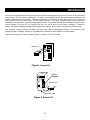
There are two ways the CIC can be installed: Figure 1- Internal or Figure 2- External.
UPS
Internal CIC
Figure1- Internal CIC
UPS
Power
Adapter
External CIC
Serial UPS cable
Figure 2- External CIC
4
Computer Interface Card (CIC) Features
The Computer Interface Card (CIC) connects directly to your UPS. It runs an embedded Simple Network Management
Protocol (SNMP) software agent. This agent responds to SNMP GETS and SETS and also forwards traps to designated
recipients when critical conditions occur within the UPS, such as the UPS going on battery backup mode during a power
failure.
The Computer Interface Card (CIC) features:
•
•
•
•
•
•
•
•
•
•
Internet ready — It supports both SNMP and HTTP protocols and user can use SNMP manager or Web browser to
monitor the UPS through a network.
Multiple OS support—As long as there is Network Management software present.
Remote setup support— Once an IP address is assigned, the rest can be setup remotely through telnet commands.
Easy USB port setup—In addition to regular serial port setup, this CIC also has a USB setup feature for the initial setup
of this card. (Requires Windows 98 or higher)
Remote monitoring—Monitors the status of one UPS from a remote workstation (Web browser or NMS).
Remote Control—Turns the UPS off (or a battery test) when the NMS sends the proper command.
NMS To Receive UPS Alarms—These traps (unsolicited messages) inform the user about the power condition of the
connected UPS.
Works with all major NMS on Ethernet—Computer Interface Card (CIC) works with the most widely used Network
Management Systems: HP Open View, Sun NetManager, IBM NetView, and many more.
Remote Software upgrade support - The Computer Interface Card (CIC) supports Software upgrade through serial
connection and TFTP server remotely.
Ring On or Reset adapter (External adaptor only)
With the external adaptor connected to a phone line: When the adaptor is on, two incoming rings will reset the adaptor.
When the adaptor is off, two incoming rings will turn on the adaptor.
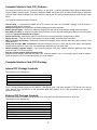
Computer Interface Card (CIC) Package
Internal CIC Package Contents
The contents of your package are:
7
7
7
7
7
Computer Interface Card (CIC)
USB Cable
DB9 Female to Female Serial Cable
3.5” Floppy Diskette
Two Retaining Screws
The 3.5” Floppy Diskette contains a UPS MIB file, USB device driver, USB setup software, TFTP Server files, and the
User’s Manual. Copy the MIB file to the appropriate NMS MIB directory for the UPS connected to your Computer
Interface Card (CIC).
External CIC Package Contents
The external adaptor is used to connect the CIC to the UPS, when the UPS does not have an option slot.
The contents of your package are:
7
7
7
7
7
7
7
7
External Adaptor Box
Power Adaptor
DB9 Male-to-Female Serial Cable
Computer Interface Card (CIC)
USB Cable
DB9 Female-to-Female Serial Cable
3.5” Floppy Diskette
Two Retaining Screws
5
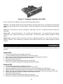
Figure 1- Computer Interface Card (CIC)
Figure 1 shows the CIC’s USB port, Serial port, Status LEDs and Ethernet port.
USB port – The USB port provides quicker setup compared to the serial setup process. The USB driver files and setup
software are both included on the 3.5” floppy diskette. Users are encouraged to use USB setup (Requires Windows 98 or
higher).
Serial port – The serial port on the front is designed for initial setup of the card. An RS232 serial cable is required for
serial setup.
Status LEDs – Three LED indicators: The first LED (red) indicates power. The second LED (green) indicates
connections, and it flashes when receiving or sending data. The third LED (yellow) indicates collisions of network
packets.
Ethernet port—Computer Interface Card (CIC) provides an unshielded twisted pair or UTP (RJ-45) connector for
10Base-T networks. Once connected, it is possible to use the ARP command to set IP address through the network
interface.
Installation
This section describes the installation of the Internal and External Computer Interface Card (CIC) when you connect it to
the UPS.
Internal CIC
1.
2.
3.
4.
5.
6.
7.
Turn off all the equipment that is plugged into the UPS.
Turn off the UPS and unplug the UPS’s power cord from the AC outlet.
Remove the two retaining screws from the option slot’s cover plate (rear panel of the UPS).
Remove the option slot’s cover plate (rear panel of the UPS).
Insert the CIC into the option slot.
Install the two retaining screws (provided with the CIC package).
Now the CIC is ready to be Setup (see the appropriate Setup Procedure).
External CIC
1.
2.
3.
4.
5.
6.
7.
8.
9.
Turn off all the equipment that is plugged into the UPS.
Turn off the UPS and unplug the UPS’s power cord from the AC outlet.
Plug the power adaptor’s connector into the connector, on the external adaptor box, labeled “Input”.
Plug the DB9 Male to Female serial cable into the connector, on the external adaptor box, labeled “To UPS”.
Plug the other end of the DB9 Male to Female serial cable into the Serial Port on the UPS (rear panel of the UPS).
Plug the power adaptor into one of the Battery Powered outlets of the UPS.
Insert the CIC into the option slot.
Install the two retaining screws (provided with the CIC package).
Now the CIC is ready to be setup (see the appropriate Setup Procedure).
6
Setup-Procedure
This section will guide you through the Setup Procedures of the Computer Interface Card (CIC).
NOTE: The minimum requirement to operate the Computer Interface Card (CIC) is to setup the IP Address.
There are four different ways to setup the CIC.
1.
Setup the IP Address via the USB port (software included). Requires Windows 98 or higher.
2. Setup the IP Address via the Serial port using Hyper Terminal. Requires Hyper Terminal version 3.0 or higher.
3. Setup the IP Address via the Ethernet Port by using the ARP command (first time only), then use the Web
Configuration to finish the setup.
4.
Setup the IP Address via the Ethernet Port by using the ARP command (first time only), then use the Telnet
Configuration to finish the setup.
Setup via the USB Port (Requires Windows 98 or higher)
NOTE: You must complete the appropriate Installation Procedure before proceeding with this Setup Procedure.
The following items must be obtained before attempting to setup the CIC: A valid IP Address, a USB Cable (provided),
the USB Driver/USB setup file (enclosed diskette) and a PC with Windows 98 or higher.
1.
2.
3.
4.
5.
6.
7.
8.
Connect one end of the USB Cable to the USB Port on the computer.
Connect the other end of the USB Cable to the USB Port on the CIC.
Plug the UPS’s power cord into the AC wall outlet.
Plug the computer’s power cord into the UPS’s output receptacles.
Turn on the UPS.
Turn the computer on and let it boot-up.
Insert the floppy diskette with the USB Driver/USB setup files into the appropriate drive.
Windows will display the following message (first time only):
New Hardware Found
USB Device
Windows has found new hardware
and is locating the drivers for it.
7
8.
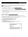
The Hardware wizard will guide you through installing the USB Driver. Click Next.
9.
The Hardware wizard will search for the best USB Driver. Click Next.
10. Check, Specify a location. Click Browse.
8
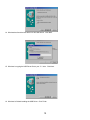
11. Open the appropriate 3.5” Floppy Drive. Open the USB folder. Open the Driver folder. Click OK.
12. Windows will search for the new USB Driver. Click Next.
13. Windows has found the USB Driver for the USB device. Click Next.
9
14. Windows has found the best Driver for this USB device. Click Next.
15. Windows is copying the USB Driver files to your “C:” drive. Click Next.
16. Windows is finished installing the USB Driver. Click Finish.
10
17. On the Desktop, right click “My Computer”. Open Properties.
18. Open the Device Manager. Wait for approximately 30 seconds for the “Human Interface Device” to appear. Open
the Human Interface Device. Click on “Usb-interface power device”. Click OK.
11
19. Open Windows Explorer. Open the appropriate 3.5” Floppy Drive. Open the USB folder. Open USBSetup.exe.
Note: The USB setup icon must be green before you can run the USB setup program.
20. The Power Device Configuration tool is loading.
12
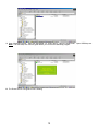
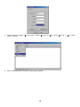
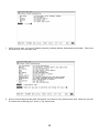
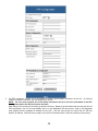
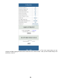
21. This is the Power Device Configuration Tool screen. On the Toolbar open Configuration. Then open System.
22. This is the System Parameter Configuration screen fill in all the information: the IP Address (required), the Subnet
Mask, the Default Route (Gateway) and the DNS Server. Use the Tab key to move from one field to the next field.
Then click OK.
13
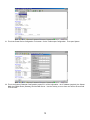
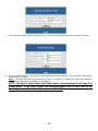
23. This is the Power Device Configuration Tool screen. After you have entered in all of the pertinent information, you
have to Update and Restart to save all the information that was entered into the System Parameter Configuration
screen. The Update and Restart icon (with the red arrow) is right beneath the “Device” drop down menu.
24. Enter the Supervisor Name and the Supervisor Password.
Password is admin (lower case). Then click OK.
14
The Default Supervisor Name and the Supervisor
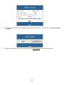
25. This is the Power Device Configuration screen. Click Yes to Update the Power Device.
26. This is the Device Parameter Transmitting screen. The Power Device is being Updated.
15
27. The Power Device has been successfully updated. Click OK.
28. The Power Device has to be Restarted. Click Yes.
29. The USB Setup Procedure is complete. The CIC is fully operational. Unplug the USB Cable from the CIC and from
the computer. Plug the Ethernet Cable into the CIC and after about thirty seconds the Link LED will start blinking,
now you can communicate with the CIC. The Ping command is supported at this time. Startup a Browser and type
in the IP Address. The default password is admin (lower case). Go to the section in the User’s Manual titled “WebBased Configuration” it will guide you through the Web pages.
16
Setup via the Serial Port
NOTE: You must complete the appropriate Installation Procedure before proceeding with this Setup Procedure.
NOTE: When using Hyper Terminal use Version 3.0 or higher.
The following items must be obtained before attempting to setup the CIC: A valid IP Address, a DB9 female-to-female
Serial Cable (provided). There are a wide variety of Terminal Emulation packages, but for the most part they should be
very similar. The following setup procedure is using Hyper Terminal.
1.
2.
3.
Connect one end of the DB9 female-to-female Cable to the Serial port on the computer.
Connect the other end of the DB9 female-to-female cable to the Serial port on the CIC.
Turn the computer on and let it boot-up.
4.
From the Desktop open the Start menu. Pick Programs, Accessories, Communications and Hyper Terminal. Open
Hyper Terminal (requires version 3.0 or higher).
17
5.
Open HYPERTRM.EXE.
6.
Enter a name (UPS). Click OK.
7.
Connect using the appropriate Com port. Click OK.
18
8.
Configure the port settings. Bits per second: “115200”, Data bits: “8”, Parity: “None”, Stop bits: “1”, Flow control:
“None”. Click OK.
9.
On the Toolbar open the File menu, and then open Properties.
19
10. Open the Settings Tab. Function, arrow and ctrl keys act as: Terminal Keys, Backspace key sends: Crtl+H,
Emulation: VT100, Telnet terminal: VT100, Backscroll buffer lines: 500. Click OK.
11. Plug the UPS’s power cord into the AC outlet and turn the UPS on.
12. When the message “Press ‘/’ key within 5 seconds to enter console configuration” appears press the forward slash
key (/) within the 5 seconds or the CIC will time out and then you have to start over.
13. Next you will be asked for the User Password. The default password is admin. Enter the password, then hit enter.
20
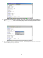
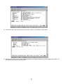
14. Ctrl-Z moves the cursor down and Ctrl-W moves the cursor up. Pick Network, then hit enter.
15. Pick IP, then hit enter. Enter in the IP Address (required), the Gateway Address, the Subnet Mask and the DNS. Hit
the “Escape” key to return to the main menu.
21
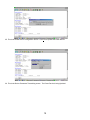
16. Enter in the PPP Type, Server IP, Client IP, Server Profile, Dial number, the ISP account/password and the
enable/disable dial-out interface (not required). Hit the “Escape” key to return to the main menu.
17. Arrow down to Mail and hit enter. Enter in the SMTP Server (not required). The user can add or delete email
addresses. Hit the “Escape” key to return to the main menu.
22
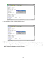
18. Arrow down to Trap and hit enter. This screen allows the user to send Traps about the UPS to ten IP Addresses (not
required). Also, you may determine the severity levels and what type of access, read only or read and write, to
assign to a particular IP manager. Hit the “Escape” key to return to the main menu.
19. Once you have finished with the entire configuration, cursor down to Save_Restart and hit enter. Make sure you
want to overwrite the old settings (y/n)? Hit the “y” key, then hit enter.
23
20. After rebooting the system, the new settings will be activated. Reboot (y/n)? Hit the “y” key then hit enter. Once the
system has rebooted, cursor down to Exit then hit enter.
21. The Serial Setup Procedure is complete. The CIC is fully operational. Unplug the DB9 female-to-female Serial
Cable from the CIC and from the computer. Plug the Ethernet Cable into the CIC and after about thirty seconds the
Link LED will start blinking, now you can communicate with the CIC. The Ping command is supported at this time.
Startup a Browser and type in the IP Address. The default password is admin (lower case). Go to the section in the
User’s Manual titled “Web-Based Configuration” it will guide you through the Web pages.
24
Setup via the Ethernet Port
NOTE: You must complete the appropriate Installation Procedure before proceeding with this Setup Procedure.
The following items must be obtained before attempting to setup the CIC: A valid IP Address, a Computer on the
network and an Ethernet cable connected to the network.
1.
2.
3.
4.
Connect the Ethernet cable to the CIC’s Ethernet Port.
Turn the computer on and let it boot-up.
Plug the UPS’s power cord into the AC outlet and turn the UPS on.
Wait for approximately thirty seconds for the Link LED to start blinking.
5.
From the Desktop open the Start menu. Pick Programs and then open the MS-DOS Prompt.
25
6.
This is an example. At the MS-DOS Prompt type: arp –s 192.166.7.19 52-54-4c-19-ad-90. Then hit enter. The first
string is the IP Address; the second string is the MAC Address (which can be found on the front of the CIC).
7.
At the MS-DOS Prompt type: route add 192.166.7.19 210.67.4.155. Then hit enter. The first string is the IP Address
and the second string is the Gateway Address.
NOTE: The PING Command is not supported at this time.
8. At the MS-DOS Prompt type exit. Then hit enter.
9. There are two options to finish setting up all of the parameters. Option #1 The Web-Based Configuration, Option #2
Telnet.
10. Option #1. Startup a Browser and type in the IP Address. The default name and password is admin (lower case).
Go to the section in the User’s Manual titled “Web-Based Configuration” it will guide you through the setup of all the
parameters.
11. Option #2. Go to the section in the User’s Manual titled “Telnet Configuration” it will guide you through the setup of
all the parameters.
26
Telnet Configuration
This section will guide you through finishing the configuration of the Computer Interface Card (CIC) using Telnet.
NOTE: You must complete the appropriate Installation Procedure before proceeding with the Telnet Configuration.
NOTE: You must have given the CIC an IP Address.
The Ethernet cable is connected to the CIC and the UPS is on.
1.
From the Desktop open the Start menu. Pick Programs and then open the MS-DOS Prompt.
27
2.
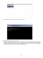
This is an example. At the MS-DOS Prompt type telnet 192.166.7.19 (IP Address). Then hit enter.
3.
Next you will be asked for the User Password. The default password is admin. Enter the password, then hit enter.
4.
Pick Terminal, then open Preferences.
28
5.
Check VT100 Arrows. You can leave the Block Cursor checked or you can uncheck the Block Cursor depending on
your preference. Then click OK.
6.
Pick Network, then hit enter.
29
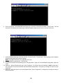
7.
Pick IP, then hit enter. Input your IP Address (required), Gateway Address, Subnet Mask and the DNS. Then hit the
left arrow key to exit to the main menu.
8.
Once you have finished with the entire configuration, arrow down to Save_Restart and hit enter. Make sure you want
to overwrite the old settings (y/n)? Hit the “y” key, then hit enter.
30
9.
After rebooting the system, the new settings will be activated. Reboot (y/n)? Hit the “y” key then hit enter.
10. The CIC has rebooted to activate the new settings. Click OK. Arrow down to exit then hit enter.
31
11. On the Toolbar pick Connect, then arrow down to exit and hit enter.
12. At the MS-DOS Prompt type exit, then hit enter.
13. The Telnet Configuration is complete. The CIC is fully operational. After about thirty seconds the Link LED will start
blinking, now you can communicate with the CIC. The Ping command is supported at this time. Startup a Browser
and type in the IP Address. The default password is admin (lower case). Go to the section in the User’s Manual
titled “Web-Based Configuration” it will guide you through the Web pages.
32
Web-Based Configuration
This section will guide you through the Web-Based-Configuration and the Web Pages of the Computer Interface Card
(CIC).
NOTE: You must complete the appropriate Installation and Setup Procedures before proceeding with the Web-BasedConfiguration.
The Ethernet cable is connected to the CIC and the UPS is on.
1.
2.
3.
Startup a Web browser.
Type in your IP Address.
Next you will be asked for the User Name and Password. The default Name and Password is admin. Enter the
password, then hit enter.
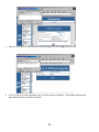
4.
This is the screen where you can set the System Information parameters for the SNMP MIB2. After you have
finished filling in all of the information, click Save.
33
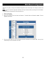
5.
This is the screen where you can set the Network parameters. After you have finished filling in all of the information,
click Save.
34
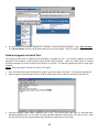
6.
The PPP connection is useful if it is not possible to make a direct network connection to the CIC. An external
modem is needed to connect to the front serial port of the CIC.
NOTE: The user must complete one of the Setup Procedures and fill in all of the information in the PPP
Configuration before the Dial-up Function will work.
After dialing in the remote user must hang up after the third ring. Based on the information that the user puts into the
PPP configuration, the CIC will automatically dial up to the designated ISP and send an email to the designated
email address with the assigned IP address from the ISP. The user may browse and control the CIC with this
dynamic IP address. When the user is ready to exit click the "Disconnect Now " button at the bottom of the screen.
35
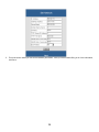
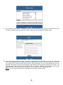
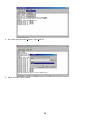
7.
This is the screen where you set the Date and Time. After you have finished filling in the information, click Save.
8.
This is the screen where you can change the Administrator’s Name and Password. After you have finished filling in
the information, click Save.
NOTE: The Supervisor’s name and password can be from 1 to 19 digits. The Supervisor’s name and password is
not limited to an alphanumeric character (i.e. a#1b$2z%9).
NOTE: Be sure to write down your Supervisor’s name/password and keep it in
a safe place. If the user forgets the name/password the CIC will have to be
Flash Upgraded before the user can access the CIC.
36
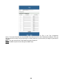
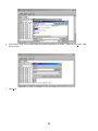
9.
This is the screen where you can upgrade to the latest version of software. See the section on Software Upgrade
Procedure.
10. When the configuration of the CIC is complete be sure to Save & Restart before exiting the program.
37
11. This screen allows the user to Logout. If, any changes were made be sure to Save & Restart before exiting the
program.
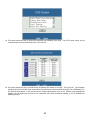
12. This screen informs the user the status of the UPS.
13. This screen identifies the UPS and the Software version of the UPS.
38
14. This is the screen where you can
configure the Data Logging intervals and the refresh rate of the meter’s screen. After you have finished filling in the
information, click OK.
39
15. This screen displays the status of the input power to the UPS.
16. This screen displays the status of the output power of the UPS.
40
17. This screen displays the status of the Batteries in the UPS.
18. This screen displays the Alarm state of the UPS.
41
19. This screen allows the User to Control the shutdown and restarting of the UPS. The UPS Control screen, list the
commands that can be executed manually. Then click OK.
20. This screen allows the User to schedule daily shutdowns and restarts of the UPS. Then click OK. The Computer
Interface Card (CIC) will NOT issue the shutdown command to the connected UPS during AC Fail, UPS Battery Low,
and UPS Fault conditions. It only notifies users or system administrator of the event. Network node management
software like HP OpenView will need to be customized with certain thresholds whether or not to shutdown the
Operating System.
42
21. This screen allows the User to schedule daily, weekly, monthly and yearly shutdowns/restarts of the UPS. Then click
OK. The Computer Interface Card (CIC) will NOT issue the shutdown command to the connected UPS during AC
Fail, UPS Battery Low, and UPS Fault conditions. It only notifies users or system administrator of the event.
Network node management software like HP OpenView will need to be customized with certain thresholds whether or
not to shutdown the Operating System.
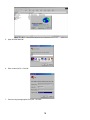
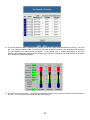
22. This is the View Graphic screen. This screen provides the user with a wide variety of information about the status of
the UPS. The user can choose the data that they want displayed.
43
23. On the left hand side of the View Graphic screen, there are seven fields that display data. The user can change any
one of these fields, to display the data that they choose, by clicking on one of the fields. Then this screen will
appear. Once the selection has been made, click OK.
24. On the right hand side of the View Graphic screen, there are three bar graphs. The user can change any one of the
Bar graphs, to display the data that they choose, by click on one of the bar graphs. Then this screen will appear.
The user can pick any one of these topics from this screen to be displayed. Once the selection has been made, click
OK.
44
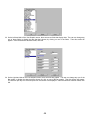
25. This is the View Data Log screen. The user inputs a start date and an end date to view data in the Data log. Then
click OK.
NOTE: The user has to enable the Data log in the Configuration screen (see page 39).
26. This is the View Event Log screen. The user inputs a start date and an end date to view an event in the Event log.
Then click OK.
NOTE: The user has to enable the Event log in the Event Action screen (see page 46).
45
27. This is the Event Action screen. The user chooses an event from the Event List. Then the user chooses one of the
five ways to configure the event (ISWITCH is used in conjunction with the RPM/UPS Interface Card).
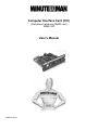
28. This is the Pager Configuration screen. Connect an external modem to the RS232 port of the CIC. When the
chosen Event happens, the CIC will page the number. After dialing in the remote user must hang up after the third
ring. Based on the information that the user puts into the PPP configuration, the CIC will automatically dial up to the
designated ISP and send an email to the designated email address with the assigned IP address from the ISP. The
user may browse and control the CIC with this dynamic IP address. When the user is ready to exit click the
"Disconnect Now " button at the bottom of the screen. The user must check the Paging Enable Box.
NOTE: The user must complete the PPP Configuration for the Pager Function to work.
46
29. This is the Broadcast Configuration screen. When the chosen Event happens, the CIC will broadcast the message.
The user will have to install the Message Capturing Program to be able to capture the broadcasted messages. The
Message Capturing Program (UpsClient.exe) is located on the CD with the User’s Manual. The program has to be
on before it will capture the messages. The user can install the program on their desktop.
NOTE: The user must check the appropriate broadcast box.
30. This is the Event Logging Configuration screen. When the chosen Event happens, the CIC will log the event in the
Event Log (see View Event Log pg.45).
NOTE: The user must check the Event Logging Enable box.
47
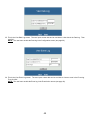
31. This is the Trap Configuration
screen. This screen allows the user to send SNMP Traps about the UPS to ten IP Addresses (managers). Also, you
may determine the severity levels and what type of access (read only or read and write) to assign to a particular IP
manager.
NOTE: The user must check the Trap Enable box and the Accept box.
NOTE: An NMS is required to send and get the SNMP Traps.
48
32. This is the Email Configuration screen. This screen allows the user to send emails about the UPS to five different
email addresses. Once all of the information is filled in, click OK. Be sure to Save & Restart before exiting the
program.
NOTE: The user must check the Mail Enable box.
33. The Web-Based Configuration is complete. The CIC is fully operational. To completely finish the Setup and
Configuration procedures the User must configure the NMS (see Configuring the NMS). Be sure to Save & Restart
before exiting the program.
49
Software Upgrade Procedures
Software Upgrade via TFTP
The user can remotely and conveniently, Flash Upgraded the CIC card’s Software via a TFTP Server. The following
procedure will step the user through setting up the TFTP Server at the user’s location and Flash upgrading the Software
for the CIC.
1.
Create a folder (TFTP Software Upgrade). Copy the following files to the folder: 2002AT ver2.0.BIN (example),
file_id.diz, tftp32.exe, tftp32.hlp, and Vendinfo.diz. The first file .BIN is the actual Software upgrade file, which is
available for downloading from our web site. The last four files are on a 3.5” floppy disk included with the CIC
package.
50
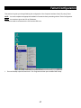
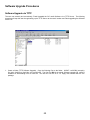
2.
Open the tftp32.exe file. The above screen will open. This is the TFTP Server’s IP address.
NOTE: DO NOT close the tftp32.exe program until the Software Flash Upgrade is complete.
3.
Open a Web browser and input the IP address of the CIC that is going to be Flash Upgraded. Once the Web page is
open, select “Software Upgrade”.
51
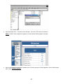
4.
Input the TFTP Server IP address and the Software Upgrade file name (.BIN), then click YES.
5.
The TFTP Server is Flash Upgrading the CIC to the new version of Software. The Software Upgrade takes
approximately thirty-five minutes to complete.
52
6.
The transferring of the Software Upgrade file is complete. Close the tftp32.exe program. Open “Save & Restart”.
The “Save & Restart” function must be performed to save all of the changes. The CIC is ready for normal operation.
Software Upgrade via Serial Port:
The following items must be obtained before attempting to upgrade the CIC: The Software upgrade file (contact
Minuteman Tech Support), a DB9 female-to-female Serial Cable (provided). There are a wide variety of Terminal
Emulation packages, but for the most part they should be very similar. The following upgrade procedure is using Hyper
Terminal.
NOTE: When using Hyper Terminal use Version 3.0 or higher.
1.
2.
Go to the section titled “Setup via Serial Port” (page 17) and follow steps 1 through 10. Then proceed with step #2.
With the Hyper Terminal program still open, Plug the UPS’s power cord into the AC outlet and turn the UPS on.
3.
Once the message “Check u-dram” appears hit the “c” key. Then at the cursor type “upgr” for cards with MAC
Addresses beginning with “52” and “upall” for cards with MAC Addresses beginning with “00”, then hit enter. Once
the user hits enter, you have approximately thirty seconds to complete the next four steps.
53
4.
Go to the tool bar and select Transfer. Open Send File.
5.
Select “X modem” under Protocol.
54
6.
Click Browse. Look in the location where the Software upgrade file is located. Select the File name: “.bin”
and click open.
7.
Click Send.
55
8.
The Software upgrade will take approximately eight minutes to complete.
9.
The Software upgrade is complete.
NOTE: The user has to reconfigure all of the settings after the Software upgrade is complete, because all of the
user’s settings will default to the original factory default settings.
56
Configuring the NMS
To complete the Computer Interface Card (CIC) installation and configuration process, you must compile the necessary
MIBs to configure the NMS.
Most NMS with a MIB compiler can manage the Computer Interface Card (CIC) adapter. For instructions on how to
compile MIBs for the most popular NMS—HP’s OpenView Network Node Manager, and SunConnect’s SunNet Manager;
see the corresponding heading below.
General Network Management Stations
Follow these general procedures to configure an NMS:
1. Compile the device MIBs.
2. Add the Computer Interface Card (CIC) object to the Management Map.
3. Ping the Computer Interface Card (CIC).
HP OpenView Network Node Manager for HP-UX
Compile the Device MIB
1.
2.
3.
4.
5.
6.
Copy the UPS MIB file from the TAR formatted diskette into the subdirectory /usr/OV/snmp_mibs.
From the main menu, select Options
Load/Unload MIBs: SNMP...
Select Load.
Select the MIB file copied earlier.
Select OK.
Add the Computer Interface Card (CIC) Object to the Management Map
1.
2.
3.
4.
5.
6.
7.
8.
9.
10.
Select the submap then Edit: Add Object.
Select the group computer.
With the middle (or opposite) mouse button, drag the generic symbol subclass device to the submap.
Enter a name for the object in the Selection and Label fields of the Add Object box.
Highlight IP Map from Object Attributes group.
Select Set Object Attributes button.
Enter Host name and IP address of Computer Interface Card (CIC) adapter.
Enter OK.
Enter OK at Add Object menu.
Enter OK at Add Object:palette.
Poll the Device OIDs
1. From the main menu, select Monitor: MIB values then Browse MIB: SNMP.
2. Move around the MIBs to view the UPS device information.
Set the Device OIDs
1. From the main menu, select Monitor: MIB values then Browse MIB: SNMP.
2. Select a MIB variable you want to alter by clicking on it.
3. Enter the new value then click on Set.
4. Click on Start Query to view the changes.
Ping the Computer Interface Card (CIC)
1.
2.
Change active Window to Shell.
Type ping <IP address> and press <enter>.
57
Access the UPS MIB variables
Keep in mind that all parameters may not be supported by every UPS system. The following list is an example of some
of the parameters. Be sure to review the MIB file contained on the floppy disk.
The Battery status
upsBattery.upsBatteryStatus.0 : batteryNormal
upsBattery.upsEstimatedMinutesRemaining.0 : 0
upsBattery.upsEstimatedChargeRemaining
The Input/Output status
upsInput.upsInputTable.upsInputEntry.upsInputFrequency.
upsInput.upsInputTable.upsInputEntry.upsInputVoltage upsOutput.upsOutputSource
upsOutput.upsOutputTable.upsOutputEntry.upsOutputVoltage
UPS Control and configuration
upsTest.upsTestResultsSummary.0 : donePass
upsControl.upsShutdownType.0 : system
upsControl.upsShutdownAfterDelay.0 : -1
upsControl.upsStartupAfterDelay.0 : -1
upsControl.upsRebootWithDuration.0 : -1
upsControl.upsAutoRestart.0 : on
upsConfig.upsConfigInputVoltage.0 : 120
upsConfig.upsConfigInputFreq.0 : 600
upsConfig.upsConfigOutputVoltage.0 : 120
upsConfig.upsConfigOutputFreq.0 : 600
upsConfig.upsConfigOutputVA.0 : 700
upsConfig.upsConfigOutputPower.0 : 450
upsConfig.upsConfigLowBattTime.0 : 2
upsConfig.upsConfigAudibleStatus.0 : enabled
upsConfig.upsConfigLowVoltageTransferPoint.0 : 92
upsConfig.upsConfigHighVoltageTransferPoint.0 : 145
UPS Identifications
upsIdent.upsIdentManufacturer
upsIdent.upsIdentModel
upsIdent.upsIdentUPSSoftwareVersion
upsIdent.upsIdentAgentSoftwareVersion
upsIdent.upsIdentName
58
Appendix
This section discusses: Communities, Gateways, IP Addresses, and Subnet masking.
Communities
A community is a string of printable ASCII characters that identifies a user group with the same access privileges. For
example, a common community name is “public.”
For security purposes, the SNMP agent validates requests before responding. The agent can be configured so that only
trap managers that are members of a community can send requests and receive responses from a particular community.
This prevents unauthorized managers from viewing or changing the configuration of a device.
Gateways
Gateway, also referred to as a router, is any computer with two or more network adapters connecting to different physical
networks. Gateways allow for transmission of IP packets among networks on an Internet.
IP Addresses
Every device on an Internet must be assigned a unique IP (Internet Protocol) address. An IP address is a 32-bit value
comprised of a network ID and a host ID. The network ID identifies the logical network to which a particular device
belongs. The host ID identifies the particular device within the logical network. IP addresses distinguish devices on an
Internet from one another so that IP packets are properly transmitted.
IP addresses appear in dotted decimal (rather than in binary) notation. Dotted decimal notation divides the 32-bit value
into four 8-bit groups, or octets, and separates each octet with a period. For example, 199.217.132.1 is an IP address in
dotted decimal notation.
To accommodate networks of different sizes, the IP address has three divisions—Classes A for large, B for medium, and
C for small. The difference among the network classes is the number of octets reserved for the network ID and the
number of octets reserved for the host ID.
Class
A
B
C
Value of First Octet
1-126
128-191
192-223
Network ID
First octet
First two octets
First three octets
Host ID
Number of Hosts
Last three octets
16,387,064
Last two octets
64,516
Last octet
254
Any value between 0 and 255 is valid as a host ID octet except for those values the InterNIC reserves for other purposes.
Value
0, 255
127
224-254
Purpose
Subnet masking
Loopback testing and interprocess communication on local devices
IGMP multicast and other special protocols
Subnetting and Subnet Masks
Subnetting divides a network address into sub-network addresses to accommodate more than one physical network on a
logical network.
For example: A Class B company has 100 LANs (Local Area Networks) with 100 to 200 nodes on each LAN. To classify
the nodes by its LANs on one main network, this company segments the network address into 100 sub-network
addresses. If the Class B network address is 150.1.x.x, the address can be segmented further from 150.1.1.x through
150.1.100.x.
59
A subnet mask is a 32-bit value that distinguishes the network ID from the host ID for different sub-networks on the same
logical network. Like IP addresses, subnet masks consist of four octets in dotted decimal notation. You can use subnet
masks to route and filter the transmission of IP packets among your sub-networks. The value “255” is assigned to octets
that belong to the network ID, and the value “0” is assigned to octets that belong to the host ID.
For the example above, if you want all the devices on the sub-networks to receive each other’s IP packets, set the subnet
mask to 255.255.0.0. If you want the devices on a single sub-network only to receive IP packets from other devices on
its own sub-network, set the subnet mask to 255.255.255.0 for the devices on that sub-network.
Subnet Mask
0.0.0.0
Routing and Filtering
IP packets are transmitted to all devices.
IP packets are only transmitted to devices that are IP that’s first octet
255.0.0.0
matches the sender’s IP address’s first octet.
IP packets are only transmitted to devices that are IP that’s first two
255.255.0.0
octets match the sender’s IP address’s first two octets.
IP packets are only transmitted to devices that are IP that’s first three
255.255.255.0 octets match the sender’s IP address’s first three octets.
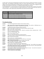
Troubleshooting
Problem:
Solution:
Problem:
Solution:
Solution:
Solution:
Solution:
Solution:
Solution:
Problem:
Solution:
Solution:
Problem:
Solution:
Solution:
Solution:
Solution:
Problem:
Solution:
Problem:
Solution:
Problem:
Solution:
The TES (Terminal Emulation Software) does not display anything.
Make sure the TES’s communication parameters are correct. They should be 115200-baud rate, no
parity, 8-data bits, and 1 stop bit. The cable is a null serial cable.
The NMS cannot ping the Computer Interface Card (CIC).
Make sure the network connection to the Computer Interface Card (CIC) is good.
Make sure the cable is in good condition.
Make sure to set the Community String. Name the community with any lowercase name. A UPS
monitors a designated community.
Make sure to set the Manager Table.
Make sure the Gateway is correct.
Make sure to Save and Restart after the Setup Procedure.
The internal CIC will not communicate and the LEDs are not illuminated.
Make sure the UPS is turned ON.
Make sure this is not a scheduled shutdown.
The external CIC will not communicate and the LEDs are not illuminated.
Make sure the UPS is turned ON.
Make sure that the external power adaptor is plugged into the UPS.
The power adaptor could be bad. Contact Tech Support.
Make sure this is not a scheduled shutdown.
The CIC will not communicate and all of the LEDs are ON.
There has been a collision of the packets. The CIC needs to be reset. Turn the UPS off and unplug the
UPS’s power cord from the AC outlet. Wait until all the LEDs on the CIC go off, then plug the UPS’s
power cord back into the AC outlet and turn the UPS ON.
The user cannot change from one Web Page to the next.
There has been a collision of the packets. The CIC needs to be reset. Turn the CIC off and wait for
approximately one minute, then turn the CIC back ON.
I forgot my Supervisor’s name/password.
The CIC will have to be Flash Upgraded.
60
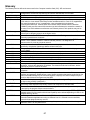
Glossary
The Glossary section defines the terms used in the Computer Interface Card (CIC) -MP environment.
Implemented SNMP applications in network elements (hosts). Agents perform the network
management’s functions as requested by the network administrator from an NMS.
Dry Closure Input Non-powered contact type inputs—switch, relay contact, open-collector.
Dry Closure Output Form C dry-contact outputs, which are common, normally open, or normally closed.
Local Area Network technology, originally developed by the Xerox Corporation, can link up to
Ethernet
1,024 nodes in a bus network. Ethernet provides raw data transfer in a rate of 10 megabits/sec.
with actual throughputs in 2 to 3 megabits/sec. using a baseband (single-channel)
communication technique. Ethernet uses carrier sense multiple access collision detection
(CSMA/CD) that prevents network failures when two devices attempt to access the network at
the same time. LAN hardware manufactures use Ethernet protocol; their products may not be
compatible.
A computer that attaches to a number of networks and routes packets between them. The
Gateway
packets can be different protocols at the higher levels.
Internet Protocol—The TCP/IP standard protocol defines the IP datagram as the unit of
IP
information passed across a network.
Internet Protocol Address—A 32-bit address assigned to hosts participating in a TCP/IP
IP Address
network. The IP address consists of network and host portions. It is assigned to an
interconnection of a host to a physical network.
Medium Access Control—The network layer between the physical and the data link layers.
MAC
Specifically, the physical (hardware) address exists in this layer.
Management Information Base—The database, i.e., set of variables maintained by a gateway
MIB
running SNMP.
Normally Closed —Refers to a contact switch that is normally closed.
NC
Network Interface Controller—The hardware interface to the physical connection to the network.
NIC
Network Management Station
NMS
Normally Open—Refers to a contact switch that is normally open.
NO
Object Identifier—The variables defined in a MIB.
OID
The current device specific software uploaded to the Computer Interface Card (CIC).
Personality
A computer that manages traffic between different network segments or different network
Router
topologies. It directs the destination IP address. The network media can be different, but the
higher-level protocols must be the same.
A specification for serial communication between data communication equipment and
RS-232
computers.
Simple Network Management Protocol—A standard protocol used to monitor IP hosts,
SNMP
networks, and gateways. SNMP defines a set of simple operations that can be performed on the
OIDs of the MIBs managed by the monitored Agents. It employs the UDP/IP transport layer to
move its object between the Agents and the NMS.
A software module that manages specific MIB sub-groups for an Agent. They communicate with
Sub-Agent
the Agent using a SMUX (multiplexer).
Transmission Control Protocol/Internet Protocol—A protocol suite used by more than 15 million
TCP/IP
users with a UNIX association and widely used to link computers of different kinds.
Terminal Emulation Software—Communications program to transform a personal computer into
TES
a terminal for the purpose of data communications.
Trivial File Transfer Protocol Server—A host to provide services according to TFTP; a TCP/IP
TFTP Server
standard protocol for file transfer with minimal capability and overhead depending on UDP for its
datagram delivery service.
User Datagram Protocol/Internet Protocol—A TCP/IP standard protocol. It enables transfer of
UDP/IP
information between applications running on different host. It is referred to as an unreliable,
connectionless datagram delivery service.
Uninterruptible Power Supply—A device that supplies power to your system with rechargeable
UPS
batteries if there is an AC power failure.
Agent
61
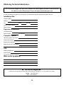
Obtaining Technical Assistance
For Technical Support on the Web, please visit the Support section of our Web site
Or visit our online Discussion Forum at www.minutemanups.com
In order to diagnose the problem you are having, our technicians need the following information from you.
Installation Site:
Company Name:
Address:
State:
City:
ZIP code:
Contact Person’s Name:
Phone Number:
If you are a consultant,
Consultant Name:
Phone Number:
Fax Number:
Computer System:
Operating System and version:
System Manufacturer:
System Model Number:
NMS name and revision number:
UPS:
Model Name/Number:
Serial Number:
Type of CIC (internal or external):
What are the symptoms?
Technical Support Please have the information listed above ready when you contact us. You can reach us by calling:
Phone: 1-972-446-7363
Fax: 1-972-446-9011
62
LIMITED PRODUCT WARRANTY
Para Systems Inc. (Para Systems) warrants this equipment, when properly applied and operated within specified
conditions, against faulty materials or workmanship for a period of three years from the date of original purchase by the
end user. For equipment sites within the United States and Canada, this warranty covers repair or replacement of
defective equipment at the discretion of Para Systems. Repair will be from the nearest authorized service center.
Replacement parts and warranty labor will be borne by Para Systems. For equipment located outside of the United
States and Canada, Para Systems only covers faulty parts. Para Systems products repaired or replaced pursuant to this
warranty shall be warranted for the remaining portion of the warranty that applies to the original product. This warranty
applies only to the original purchaser who must have properly registered the product within 10 days of purchase.
The warranty shall be void if (a) the equipment is damaged by the customer, is improperly used, is subjected to an
adverse operating environment, or is operated outside the limits of its electrical specifications; (b) the equipment is
repaired or modified by anyone other than Para Systems or Para Systems-approved personnel; or (c) has been used in a
manner contrary to the product's operating manual or other written instructions.
Any technical advice furnished before or after delivery in regard to use or application of Para Systems’s equipment is
furnished without charge and on the basis that it represents Para Systems’s best judgment under the circumstances, but
it is used at the recipient's sole risk.
EXCEPT AS PROVIDED HEREIN, PARA SYSTEMS MAKES NO WARRANTIES, EXPRESSED OR IMPLIED,
INCLUDING WARRANTIES OF MERCHANTABILITY AND FITNESS FOR A PARTICULAR PURPOSE. Some states
do not permit limitation of implied warranties; therefore, the aforesaid limitation(s) may not apply to the purchaser.
EXCEPT AS PROVIDED ABOVE, IN NO EVENT WILL PARA SYSTEMS BE LIABLE FOR DIRECT, INDIRECT,
SPECIAL, INCIDENTAL, OR CONSEQUENTIAL DAMAGES ARISING OUT OF THE USE OF THIS PRODUCT, EVEN
IF ADVISED OF THE POSSIBILITY OF SUCH DAMAGE. Specifically, Para Systems is not liable for any costs, such as
lost profits or revenue, loss of equipment, loss of use of equipment, loss of software, loss of data, cost of substitutes,
claims by third parties, or otherwise. The sole and exclusive remedy for breach of any warranty, expressed or implied,
concerning Para Systems’s products and the only obligation of Para Systems hereunder, shall be the repair or
replacement of defective equipment, components, or parts; or, at Para Systems’s option, refund of the purchase price or
substitution with an equivalent replacement product. This warranty gives you specific legal rights and you may also have
other rights, which vary from state to state.
Longer term and F.O.B. job site warranties are available at extra cost. Contact Para Systems (1-972-446-7363) for
details.
63