1
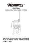
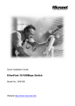
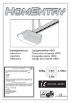
Touch Screen
Extender
VGA Data Extender
VDE-300
Transmitter : VDE-300T
Receiver : VDE-300R
User Manual
User Manual
VDE-300
Transmitter : VDE-300T
Receiver : VDE-300R
(C) 2006 Green-Box Technology Co., Ltd.,
All Rights Reserved
TABLE OF CONTENTS
4
Introduction
5
Key Features
6
Panel Description
7
Installation and Operation
14
Specification
14
Order Information
15
Remarks
User Manual
/ Introduction
VDE-300 is an extension system to transmit VGA and RS-232 Data (Tx/Rx)
over Cat5/5e/6 cable up to 300 meters. VDE-300 consists of a Transmitter
and a Receiver unit, the Transmitter is placed near PC and the Receiver
near Touch Screen. And then use Cat5/5e/6 cable to link together. It is
suitable for the interactive application of Touch Screen Extension and Flat
Panel Remote Control. It can simplify the installation, ease to maintain and
reach a longer distance. The video quality can be adjusted very easily from
the FOCUS and GAIN Control in the Receiver. Now, you can centralize PC
and servers in a secured place and extend the VGA and Data signal up to
300 meters to fulfill multi-purpose application.
The VGA Data Extender is designed not only to provide accurate signal, but
also easy to install. It provides a magnetic pad on the bottom of unit and an
attachable metal plate, so you can place the VGA Data Extender very easily
on the surface of PC or any preferred place like wood or concrete plane.
/ Key Features
1. Extend VGA and Data signal over Cat5/5e/6 cable and the maximum
VGA resolution is up to 2048x1536@300m
2. Bidirectional serial RS-232 (Tx/Rx) control
3. Remote and local monitors can display simultaneously.
4. Use Cat5 Enhance UTP cable (350MHz bandwidth) for best quality
(for long distance, the Belden DataTwist 350 UTP - #1700A-Solid is
suggested)
5. Software free, pure hardware design, support Plug & Play
6. Support VGA, SVGA, XGA, TFT_LCD with DDC2B function
7. Provides a magnetic pad and attachable metal plate to ease the
installation
8. Transmitter VDE-300T:
(1)Built in one set of VGA(DB15) and Data(with a DB9 adaptor cable) inputs
(2)Built in one set of VGA(DB15) output for monitoring
(3)Built in one RJ-45 port for system output which can be connected by
UTP cable and send signal to one set of System Receiver
9. Receiver VDE-300R:
(1)Build in video and focus control to adjust the video quality, the maximum
extended VGA resolution and distance up to 2048x1536@300m.
(2)Built in one set of VGA(DB15) and Data(with a DB9 adaptor cable)
output for Touch Screen
(3)A PS/2 connector to provide DC5V power for Touch Screen’s RS-232
control.
User Manual
/ Panel Description
❶
❶
❷
❽
❸
❹
❺
❻
❼
Magnetic Pad
❸
❹
VDE-300T
❶
❷
❸
❹
Tx / Rx Status
DC 5V out for Touch Screen
Power Jack (Optional)
To Monitor
DB9 Female VDE Cable
❾
❿
❽
❼
VDE-300R
❺
❻
❼
❽
To Serial port
To PC VGA
System Link
❾
❿
To Serial connesction
of Touch Screen
Video Control
H & V Sync Activity
VGA Cable 1M
DB9 Male VDE Cable
/ Installation and Operation
1. VGA Data Device Installation
(1)Setup: In the beginning, please follow the instruction of the user
manual of VGA Data Device to install and test its basic function. Such
VGA Data device can be Touch Screen, Flat Panel or Projector with a
RS-232 Tx/Rx control and in this manual we are using Touch Screen
to illustrate the installation. Please note that you might need to install
certain software to activate the RS-232 Tx/Rx communication.
(2)After testing above device locally, you are ready to use VDE-300
to extend the VGA Data signal over Cat5/5e/6 cable and control
remotely.
2. VDE-300T Transmitter Installation:
(1)Site Selection: Place Transmitter near the PC; you can use magnetic
pad to attach the unit on a metal plane (Ex PC / Server enclosure) or
use attachable rack mounting kit to fix the unit on selected area by
screw or nail.
Unit attached with Rack Mounting Kit and the Rack Mounting Kit
User Manual
(2) UTP Cable Selection: For best VGA performance, you can refer
to following type of UTP Cat5 cable - Belden DataTwist 350 UTP #1700A – Solid, Belden DataTwist 350 patch - #1752A – Stranded, or
Belden DataTwist Category 5e – 1583A – Paired cable.
Transmitter
VGA
RS-232 (Tx/RX)
❶
Monutor
❷
AC7 5V Power Adaptor
❶
DB9 Female VDE Cable
❷
VGA Cable Male to Female 1m
(3) Power On: Plug power adapter to the Receiver and connect Touch
Screen’s VGA and Serial connection to Receiver. For most of the
Touch Screen (Serial Connection), it will be required to take the power
from PS/2 to activate the Tx/Rx communication, so the Receiver has
built in a PS/2 port to provide a DC5V power for Touch Screen. The
LEDs of the STATUS will stay on Blue to indicate power on status
and the RJ-45 LEDs will blink to indicate the unconnected status of
Cat5/5e/6 cable.
3. Receiver Installation and UTP Connection:
(1) Site Selection: Please place Receiver in an appropriate place and
have the UTP cable (Cat5/5e/6 cable and Cat5e is preferred) settled
for later connection. You can use magnetic pad to attach the unit
on a metal plane (Ex PC / Server enclosure) or use attachable rack
mounting kit to fix the unit on selected area by screw or nail.
Unit attached with Rack Mounting Kit and the Rack Mounting Kit
(2) UTP Cable Selection: For best VGA performance, you can refer
to following type of UTP Cat5 cable - Belden DataTwist 350 UTP #1700A – Solid, Belden DataTwist 350 patch - #1752A – Stranded, or
Belden DataTwist Category 5e – 1583A – Paired cable.
(3) Power On: Plug power adapter to the Receiver and connect Touch
Screen’s VGA and Serial connection to Receiver. For most of the
Touch Screen (Serial Connection), it will be required to take the power
from PS/2 to activate the Tx/Rx communication, so the Receiver has
built in a PS/2 port to provide a DC5V power for Touch Screen. The
LEDs of the STATUS will stay on Blue to indicate power on status
and the RJ-45 LEDs will blink to indicate the unconnected status of
Cat5/5e/6 cable.
The PS/2
Connector is Used
to Provide a DC5V
Power for Touch
ScreenMounting Kit
6
5V
5
4
3
1
1
User Manual
Receiver
VGA
RS-232 (Tx/RX)
❸
Touch Screen
AC7 5V Power Adaptor
Gain & Focus Control
To
Touch
Screen
❸ DB9 Male VDE Cable
(4)Connect UTP cable: Plug two ends of UTP cable to Transmitter and
Receiver’s RJ45 SYSTEM LINK ports. (Please make sure that these
two ends should be made by 586B/568B type.) Now the LEDs above
RJ-45 should remain ON to indicate the activation of video signal
and the correct connection of UTP cable. If the LED keeps blinking,
please check if there is any error to exist.
VGA
VGA
RS-232
(Tx/Rx)
Monitor
❶ ❷
AC7 5V
Power
Adaptor
❸
RS-232
(Tx/RX)
Gain & Focus
Control
Touch Screen
AC7 5V
Power
Adaptor
Use Cat5e cable Max : 300M
Transmitter
System Diagram of VGA Data Extender
10
Receiver
❶ DB9 Female VDE Cable
❷ VGA Cable 1M
❸ DB9 Male VDE Cable
(5)Function Test: Power on the Touch Screen or other VGA Data
Devices and then boot up your PC. You should be able to test the
function of Touch Screen remotely, and during the operation, the
STATUS LED will keep blinking between blue and red to indicate the
Tx/Rx data communication.
(6)Manual VGA Adjustment: The video quality can be manually adjusted
by the control of GAIN and FOCUS in the back of Receiver unit.
(7)VGA Problem & Solving: If you find unstable image or unable to
display after the installation, please confirm following items or contact
your direct vendor for further assistance
A. Check if PC’s VGA resolution and frequency over the limit
of monitor, if so, please change the VGA configuration to an
acceptable level.
B. Ensure all equipment has correct grounding and AC outlets on the
same electronic phase; also don’t use 2-wire extension cord to
prevent potential power damage or interference.
C. Check if the Receiver’s power adapter is AC7.5V with a capacity
over 1 Amp.
D. Try to connect Touch Screen directly to PC, and ensure the basic
function of VGA output, monitor display and Touch Screen control.
E. If using LCD monitor, there might have some image offset or
blinking, please adjust the position, clock or phase of monitor
status, or simply press “Auto Adjust/Tune” to have a better image
solution.
11
User Manual
(8)RS-232 Tx/Rx Problem & Solving: If you have any RS-232 Tx/Rx
irregularity during installation or operation, please try following items
A. Transmitter Unit Check: In the Transmitter side, try to connect the
Touch Screen directly to your PC to verify the regular function. Or
try to reboot your system or change connected devices to have
your original PC signal working normally.
B. Receiver Unit Check: Try to unplug and plug the power adapter,
and verify the LED indicators, and reconnect UTP cable, make
sure SYSTEM LINK LED turn on normally, and then check the
basic function of Touch Screen.
4. Other System Integration:
(1)Illustration of More Touch Screen installed in a PC: If you have a
Multi-Console PC, you may connect more Touch Screens to save
the equipment cost and take the advantage of VGA Data Extender to
locate PC in a secured place and to provide a simple way to maintain.
RS-232
(Tx/Rx)
Monitoring
Using Switch
VGA
VGA 2
RS-232
VGA 1
(Tx/Rx)
RS-232
(Tx/RX)
Touch Screen
Transmitter
Transmitter
Use Cat5e cable Max : 300M
Receiver
VGA
RS-232
(Tx/RX)
Touch Screen
Receiver
Use Cat5e cable Max : 300M
System Integration for a Multi-Console PC supporting Two Extended Touch Screens
12
(2)KVM Switch and Drawer: If you have more than one PC in a location,
you may use a KVM Switch to control many PCs through one KVM
console (Keyboard / Video / Mouse), or use integrated KVM Switch –
KVM Drawer to use just 1U space to control many computers.
(3)Remote and IP Solution: In addition to KVM Switch, you may extend
the KVM control by KVM Extender up to 300 meters or use IP KVM
solution to control PC / Servers from intranet or internet.
(4)For more detailed information or consultation, please contact your
system supplier.
13
User Manual
/ Specification
Model
Spec.
Description
VDE-300T
VDE-300R
One-Port AV Transmitter
One-Port AV Receiver
AV Input
DB15/DB9
RJ45
AV Output
DB15/RJ45
DB15/DB9
Video CTRL
N/A
LED
Power Input
AC7.5V
AC7.5V
-
DC5V
Power output
Video Quality
Dimension (U×W×H)
Gain/Focus
Tx / Rx
1280×1024×60Hz@300M, 1600×1200×60Hz@200M
62×113×29
62×113×29
/ Order Information
14
Order Details
Part Number
Remark
VDE-300 Transmitter
VDE-300T
With Power Adaptor x 1, DB9
adaptor cable x 1, Rack Kit x 1
VDE-300 Receiver
VDE-300R
With Power Adaptor x 1, DB9
adaptor cable x 1, Rack Kit x 1
/ Remarks
1. Before operating this system, please read operation manual carefully.
2. Please use correct power adapter and use high quality cable for optimum
broadcasting.
3. To prevent potential power damage, please don’t use 2 –wire extension
cord and ensure AC outlets at relative devices on the same electronic
phase and have correct grounding.
5. Limited Warranty:
(1) In no events shall the direct vendor’s liability for direct or indirect,
special, incidental or consequential damages, loss of profit, loss of
business, or financial loss which hay be caused by the use of the
product exceeds the price paid for the product.
(2) The direct vendor makes no warranty or representation, expressed or
implied with respect to the contents or use of this documentation, and
especially disclaims its quality, performance, merchantability, or fitness
for any particular purpose.
(3) The direct vendor also reserves the right to revise or update the
product or documentation without obligation to notify any user of such
revisions or updates. For further information, please contact your
direct vendor.
15