1
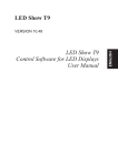
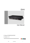
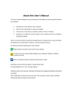
Installation of LED Flash Screen
Chapter 1: Product Acceptance………………………………………………….. Page 2
1.1Introduction of LED flashing screen accessories……………………
Page 2
1.2 LED flashing screen accessories inventory……………………………
Page 2
Chapter 2: Hardware Assembling……………………………………………..…. Page 2
2.1 Splice LED flashing screen…………………………………………..
Page 2
Chapter 3: Software…………………………………………………………….….
Page 12
Chapter 4: Effects Production…………………………………………………...…Page 13
4.1 Material Preparation………………………………………………………..
4.2 Use PS to make GIF format animation...……………………………….
4.3 Use LED flashing screen to play the animation……………………….
Page 13
Page 13
Page 16
Chapter 5: Appendix……………………………………………………………...….Page 18
Chapter 1 Product Acceptance
1.1 Introduction LED flashing screen various accessories
LED flashing screen accessories include:
1: Colorlight A8 control card (Appendix Figure 1)
2: HUB12 riser card (Appendix Figure 2, the HUB12 riser card cable port numbers maybe
different based on the LED flashing screen size, to prevail in kind)
3: Standard Red and Black cable length 375mm (Appendix Figure 3)
4: Data cable 16 core length 172mm and 16-core length 390mm above (appendix figure
4)
5: Product suffix power cord length 1.5m (Appendix Figure 5)
6: Power supply 5V / 40A / 200W. LED flashing screen size maybe different according to
the order requirement (Appendix Figure 6)
7: 3-in-1 switch (Appendix Figure 7)
8: Network port extension cable 3M length (appendix Figure 8)
9: Network cable (Refer to 586B wiring diagram)
10: LED flashing screen 320 * 160 (Appendix Figure 9)
11: 18# Red and Black lines
1.2 LED flashing screen accessories inventory
1: Colorlight A8 Control Card
2: HUB12 riser Card
3: Standard Red and Black cable length 375mm
4: Data cable 16 core length 172mm
5: Data cable 16 core more than 390mm
6: Product suffix power cord length 1.5m
7: 3-in-1 switch
8: 3M long network port extension cable
9: cable
10: Power supply
11: LED flashing screen
12: Data cable 50 core length 65mm
13:18# Red and Black lines;
(More specific quantity, See delivery list)
Chapter 2: Hardware Assembling
2.1 Splice LED flashing screen
1. According to the flashing screen size, take out the number of lateral LED flashing
screen module, placed neatly, can’t be misplaced or bent. Hook the edge of the board with
a tape measure, the measuring size is the display length.
2. Minus 1-2 mm of the measured actual size as the sizes of materials.
3. Vertical display the LED flashing screen module, the measured size is the width of the
LED flashing module (Please note that the direction of the arrow on the screen flashing
LED module need to be consistent.
Assembly
4. After getting the material, first drill the hole, and then use the self-tapping screws or
rivets to assemble the frame. Please note that the fixing holes need to be drilled to the
place that the plastic corner contacting with the profiles.
5. Fix the flat iron. After screw on the magnet to the flashing LED screen module, cut the
flat iron according to the corresponding width of the frame. Fix the flat iron to the frame
with self-tapping screws or rivets. Please note that the flat iron is screwed on to the edge
of the unit board, so that two unit boards can share one flat iron. Usually, the flat iron
should be drilled on one side and fixed first, then drill on the other side. When drilling, you
need to squeeze the frame together, so that the frame will not be deformed.
Drilling holes
Fix the flat iron
6. After all flat iron fixed, use a vacuum cleaner to suck clean the aluminum shavings, dust
at the back of the screen. Residual aluminum scrap may cause a short circuit, burning
LED flashing screen modules or other components.
7. Place the LED flashing screen modules to the frame then can begin wiring up;
LED flashing screen modules
A: This socket is connected with a 16 core data cable and riser card, with anti-inserted
upside gap;
B: This two white arrow indicates the transmission direction of the signal;
C: is the power connector, +5 denotes positive, GND denotes negative;
D: This socket is connected with a 16 core data cable (172mm length)and the next LED
flash screen module, with anti-inserted upside gap;
E: This is a four permanent stone for fixing the flashing LED screen module;
Power supply:
A: + V is the output of the positive electrode, the 3 connection ports are connected with
the "+ 5V" power interface of the LED flashes screen module;
B: COM is the output negative electrode, the 3 connection ports are connected with the
"GND" power interface of the LED flashes screen module;
C: L / N these two ports are 220V, no positive and negative points;
Power connector,
the left positive,
and right negative
Cable interface,
any one is OK
Touch the button,
Mode button
Control signal
channel
Transverse signal 8 channels
(also have16 channels)
The channels numbers determine
how many rows of the flashing screen
The socket connected with the riser card
and A8 control card.
LED flashing screen assembly steps:
The above picture is the assembled LED flashing screen; now begin the explanation of
the assembly steps;
1: Put the flashing screen to the stand according to the corresponding size, pay attention
to the direction;
A8 Colorlight control card data lines must be connected from left to right.
2: Connect the data cable, with 16 core data cable (172mm length) from left to right in
series;
After the completion of each row connected in series, connect the first socket of the first
row of the left side of the first to the J1 socket of the riser card with 16 cores (390mm
length above); similarly, connect the second row to the J2 socket, and so on.
When connecting the data cable to the riser cards,
When the data cable is inserted to
the
The red line of the data cable is in front of letter A. LED flash screen module there’s anti
inserted upside gap.
3. Connect the riser card to the A8 control card.
Connect the riser card to the control card with 50 core 65mm length data cable, pay
attention to the direction.
There are two white triangle on above picture is the direction identifier.
4. Connect the power cord to LED flash screen module and the control card.
Connect the LED flash screen with the standard Red and Black power cord.
5. Connect the LED flash screen module, control card and power cord.
According to the power of the power supply and one unit LED flash screen module power,
can calculate how many pieces LED flash screen modules can be connected in
one power
supply. Usually when using the power supply, there’s 20% margin left. E.g.:
Power supply is
200w, the LED flash screen module is 15W, then the maximum numbers of the modules is
200*0.8/15=10.
6. Connect to power supply 220V.
e.g.: Use 5 power supplies, only parallel with the L/N port of the 5 power supplies.
7. Assemble the accessories and then fix to the stand, plug the 3-in-1 switch
to the power
Supply and then you can start debugging the effect. If not connecting to
the computer, you
can press the only touch button of the A8 control card, and then you can debug
the effect of
the LED flash screen.
Chapter 3
The control software of the LED flash screen is 【LEDSHOWT9】, please see the software
User’s manual about the usage of the software.
Click “Help”-click on the drop-down menu of the first item, it is the user’s manual.
Chapter 4
4.1 prepare the materials.
Prepare the effected pictures (For example the following car ads), and PS software.
4.2 use PS to make GIF format animation.
1: LED flash screen is white color, so only need Black and white color when make
the effect.
2. Open the picture with PS:
3. There’s a button about the setting background color.
4. Set the background color to Black color.
5. Use
polygonal lasso function to select the picture outside of the car, press
Delete button.
6. Use
magic wand function to remove excess color, leave only car.
7. Set the background color to White color, use the above method to delete the car.
This is one frame of a GIF animation.
8. GIF is animated frame by frame, that is to say, when the animation is moving each time,
it shows one or more frames.
Open all the prepared pictures with PS.
A. Click the menu “File”-click the drop-down menu “Open”-choose all the 25
pictures-click open.
B. Click the menu “Window”- click the drop-down menu “Animate”, will appear animation
plate.
C. Press F7 to open the layer.
D. Right-click the blue color of the picture, left-click the “Background layer” of the
drop-down menu-click OK on the pop-up windows.
Repeat this operation on other pictures.
E. After finished the above operation, use
moving tool to move the 2-25
st
pictures, totally 24 pictures to the 1 picture and overlapping. And then close the 2-25
pictures.
Now there’re 0-24 layers on the layer panel, which is the following 24 frames
animation. The eye signal is the layer switch.
F. Click the right bottom of the animation panel
Go into animation “Frame” panel.
, there’re 3 dot buttons.
G. Click
add “Frame” add 24 frames.
H. Click the 1st frame, select the layer you want to display in the Layers panel.
Click the 2nd frame, select the layer you want to display in the Layers panel.
And so on, select all the layers you want to display in the Layers panel.
I. After select all of the layers, then set the display time of each frame, click:
the triangle on the right bottom, click the time you want to display on the
drop-down menu.
J. After setting the time, you can click
play button to preview GIF animation.
K. Click menu bar “File”-click “Storage to WEB equipment used format” on the
drop-down menu. Select “GIF” format from the pop-up window. After the progress bar
100%, click “Storage”- Select the storage path-click save.
After this step, congratulations! Your animation is complete.
4.3 display animation with LED flashing screen.
1. Connect the computer and the control card with the network cable, open
“LEDSHOWT9”, click the menu bar “Control the screen”-click the drop-down menu
“Screen management”, click “Detection receiver card” on the pop-up windows. The
results will be displayed in the blank.
2. Open “LEDSHOWT9”, click
, click the drop-down menu “Blank program
page”, click
program 1-right click “program 1”-click the
drop-down menu “Add File window”, right click the file window-click “Add GIF” on the
drop-down menu-select the GIF file from the pop-up window, click “OK”, GIF file is
completed loaded.
3. Click “Play”
, you can see
on
the computer desk, now the LED flash screen can also display, move or zoom the
yellow box when it displayed at the edge of the screen.
4. When need for offline play, click
Send program to control card.
Click the “send” button of the above picture, when sent successfully, you can
disconnect the network cable for offline broadcast.
The end, I wish you success!
Chapter 5
Appendix:
Figure 1
A8 Colorlight control card
Figure 2
Riser card
Figure 3
Standard Red and Black connect line
Figure 4
16 core 172mm length data cable
Figure 4
16 core above 390mm length data cable
(Figure 5) Product Suffix Power Line
(Figure 6)
200W power supply
(Figure 7)
3-in-1 switch
(Figure 8)
Network port extension cord
(Figure 9)
LED flash screen module