1
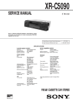
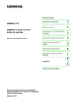
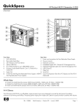
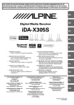
Rapid Observations of the Solar Atmosphere
(ROSA) User Manual
Damian J. Christian ([email protected])
David B. Jess ([email protected])
Gareth Dorrian ([email protected])
Queen’s University Belfast
March 2010 v2.0
I. General
-ROSA is comprised of 6 imaging fast readout CCD cameras.
-The maximum frame rate for:
• full chip (1004x1002 pixels) is 30 frames per second
• binned chip (binning 2,2 502x501 pixels) is ~60 frames per second
• windowed chip (100x100 pixels) is ~1251 frames per second
-All 6 ROSA cameras are triggered from a synchronization box.
Two options for the synchronization:
• All 6 cameras are synchronized to the same pulse
(with an accuracy of ~33 μs)
• A choice of 4 different synchronized triggers
1
Theoretical rates are 250 fps for 100 x100 pixels but tests only showed about 125 fps written to disk.
II. User Interface : ROSA is controlled via a graphical user interface
(GUI). This GUI allows the user to select and modify the Sync box
parameters and all of the set-up parameters for each individual camera.
When running, the interface displays an image from each camera about once
per second.
A. Main Interface (Sync Control)
The main control for ROSA is the GUI interface to the Sync box. It
automatically loads when the Firefox web browser is started. The main
parameter to be set is the frame rate. For full chip mode this should be set to
0.034 seconds (or a rate of 29.4 fps). There are then 4 different Sync timing
rates that can be chosen and set to multiples of this main rate. Each camera
can then be set to 1 of these 4 sync timing rates. The default is to trigger the
cameras from the first sync rate. Please see Figure 1, which shows the main
ROSA GUI/Sync Box interface. Once all observing parameters are set, the
user can start taking data by selecting the START OBSERVING button neat
the bottom of the GUI. This will load a new web page showing an image
from each of the 6 cameras and a frame count. There is a STOP
OBSERVING button near the button of this GUI that will stop the current
acquisition.
The individual camera interfaces are accessible along the bottom of the
interface and here the user can set the camera’s exposure time and
parameters (such as temperature, gain, and binning) and we now discuss
these interfaces in mode detail below.
Figure 1. ROSA main GUI interface and Sync box control. In this example
the frame rate is set to 29.41 frames per second.
B. Camera Set-up Interface
The Camera GUI accesses the camera in real time and displays its current
image (using the cameras internal mode) and shows the allowable frame rate
for its current set-up (shown in Figure 2). The default temperature is -75 C
and the user should turn on cooling if not already on. The user can set the
exposure time, binning (2x2), windowing in X and Y. There are additional
options to turn off baseline clamping and to increase the electron multiplying
(EM) gain. The range of EM gain values are 0 to 255 and the default is 0 or
no additional gain.
Please note that when accessing a camera’s page for the first time it takes
several seconds to update and you may see the word Error before the camera
temperature appears or you may see the temperature in red (-74) before it
updates. On rare occasions the camera may be busy and you will see a
Timeout (please see Section VI about this).
Figure 2. Camera Set-up page for Das2.
III. Observing Modes
A. Science Acquisition …
If you want to check what a particular camera is imaging: then just go to
that cameras set-up page and you will get a real-time video image of that
camera.
DUNN Filter choices (TBD)
There are several different instruments at the DST that ROSA can be used
with.
The 3 pairs of ROSA cameras can be combined to observe in various blue
and red filters in either narrow or continuum bands, and several filter
combinations are offered by the DST.
These include:
Ca H&K,
G-band,
350 nm,
Hα,
Tunable filters
Universal Birefringent Filter (UBF).
The UBF is an unique instrument at the DST and it can be tuned to any
observable wavelength in the 400 to 700 nm range. It has various modes of
operation, including Direct Imaging Mode (i.e. intensity measurements),
Magnetic Field Mode (longitudinal magnetic field measurements), and
Doppler Mode.
SPINOR
Others…
Combination with SPINOR/IBIS/Other
B. Calibration Frames – choices are given on the camera set-up pages.
key words are passed to main fits header and the file name is appended with
BIAS/DARKS/FLATS for:
• Bias - Shutter Closed & 0 sec exposure
creates files like: das1_rosa_bias_2008-07-01_11.59.59_0000.fit
• Dark -Shutter closed, but exposure time set by User (exp > 0).
creates files like: das1_rosa_darks_2008-07-01_11.59.59_0000.fit
• Flat field – shutter open & exposure time set by User.
creates files like: das1_rosa_flat_2008-07-01_11.59.59_0000.fit
In the Figure below, is an example with the camera interface set to take a
bias. By selecting bias the camera shutter is forced closed (e.g Force Shutter
Closed is ON) and the exposure time is set to 0. When switching back to
another observing mode you will get a warning to set a non-zero exposure
time in a pop-up window (see Figure 3b).
Figure 3a. Camera DAS2 set-up to take biases.
Figure 3b. Shows the warning for a 0.000 exposure time when selecting
another observing mode.
C. Other Camera Settings
Binning: You can set the Binning X and Binning Y each to 2 for a 502x501
Binned images. However if you want binning such as 4x4 you need to adjust
the frame size to be an integer multiple of 4, such as making X finish and Y
finish 1000 in the Camera GUI interface.
Gain: Allowable gain values are from 0 to 255. Using a non-zero gain value
increases the amplification, but this mode is largely untested.
Baseline Clamp: Having this ON removes the noise from the CCD
normally seen as a linear ramp in the first ~100 frames. Default is ON.
Fast Trigger Mode: It is unclear this mode does anything. Please ignore.
Global Setup: If you want the current set-up for the current camera to be
applied to the other 5 cameras just click on Global Setup button. This takes
a few seconds for each camera to be updated and if you are near the cameras
you will here all 5 shutter open and close in sequence. Please wait at least 10
seconds after selecting the Global Setup update!
Timer Setup: This returns the user to the main GUI interface to the Sync
box.
IV. Running ROSA
Starting an observing sequence:
From the main ROSA GUI interface you have set:
Set your frame rate, sync triggers and camera triggers
All camera coolers on for at least 10 minutes
(green = cold/OK, yellow = cooling/warming, red = warm)
Set- camera exposure times 1-6 (or for cameras in use).
You can set all camera from the current camera by
Selecting Global Setup
Select START OBSERVING button and take data!
(a frame number of 00000 will take data until it is stopped).
An example of Camera Status page displayed during observing
with all 6 cameras is shown in Figure 4.
Select the STOP OBSERVING button to end the current sequence.
Figure 4. ROSA Observing page with all 6 cameras (1, 2 & 5 active).
V. DATA Format & Storage
Data formats :
The ROSA data are saved in FITS format with a main header in frame
[0] and then sub-images from 1 to 255, for Frames per file set to 256 (see
individual camera set-up pages). This produces about a 500 MB file for the
default value of 256 frames per file. This parameter is adjustable by the user.
The main FITS header includes information from the sync box and camera
set-ups. The Dunn Common Services Server (DCSS) is interrogated every
10 seconds to obtain telescope pointing information, which is updated to the
main fits header [0].
Data Storage: Each 2 DAS PCS has its own dedicated DLT Tape Storage
unit.
VI. Trouble Shooting
1. One of the more common annoyances of ROSA is that some of the
camera images will not display when acquiring data. (In general data is still
being taken, just no real time image from the camera is being displayed in
the browser). If this happens you can use the re-load button on Firefox. If
this solves the problem no further action is needed. If the camera image is
still not displayed you can double check that data is being written by looking
into the individual data directory: /export/data/rosa on the das for that
camera or by running /home/rosa/bin/chkdas.pl
On some occasions you may need to re-start Firefox
2. When observing you see on the Camera set-up page: Timed Out instead
of a temperature. This means the camera was busy at the start of the
acquisition. Stop and Re-start observing. If this fails, then you may need to
restart the camera server on that DAS PC. Check the camera server on that
das with
ps –ef | grep Camera. If it is not running restart with ./camera.sh
3. When observing you see on the Camera set-up page: No connection to
host instead of an image. This means the camera server went down and
needs to be restarted. Please go to that particular das and restart the camera
with ./camera.sh and then re-start observing.
4. Sometimes after re-starting the system the cameras do not readily see the
sync box. The camera set-up page will show a live image, since this is from
internal mode, but the live observing image will be fuzzy.
Check that the sync box is up with:
/home/rosa/atpcu/examples/info/maker/info
If the sync box is up, this will show:
1 PCU Device(s) detected.
Device 1 Serial Number : IO-1517
Press Enter to Exit.
Check that the timer is up from starting Firefox with:
ps –ef | grep Timer
If the timer is down, re-start Firefox.
Set-up 1 camera and apply this setting to all other cameras with
Global Setup
Re-start and observation sequence and the problem should be solved.
5. Sometimes a camera overheat alarm will sound. This indicates that the
cooler has deactivated for some reason. This can happen for a number of
reasons, including a disruption in the cameras connection to the server. If
this should happen first try simply directing a fan at the camera and lifting
any of the light rejection covers to release warm air. This sometimes works
after a few minutes. If the alarm does sound check that the cooler is switched
on in the Firefox GUI camera setup page for that particular camera. If the
alarm still sounds, try using the killall -9 Camera command in the DAS
terminal for that camera and then restart it using the command
/home/rosa/bin/camera.sh. If this fails to work and the alarm still sounds
once it has been restarted then power cycle the appropriate DAS machine.
The cooler on Camera 2 is currently inoperative.
APPENDICIES:
A. CCD Specifications
Table 1: An overview of the software requirements for the ROSA CCD
specifications
Model
Andor iXon+ DU-885K-VP
Size
1004(H) x 1002(V)
Pixel size
8 x 8 μm
Frame rate (full chip)
30 fps
Read noise
0.02 e/s/pixel
Data Output
14 bit
QE (400 nm)
>40%
QE (600 nm)
>60%
QE (800 nm)
>40%
Table of Camera parameters
Camera
Bias
X2996
301
X3063
280
X3071
302
X3075
300
X3131
299
X3133
304
Dark Current
0.014
0.013
0.019
0.016
0.019
0.013
(e/pix/sec)
Comment
B. Quick Start-up Guide
The following procedure outlines the method required to allow the
instrument user to obtain data with the ROSA system. Please follow all
commands IN ORDER, beginning with a completely OFF instrument.
1
2
3
4
Plug AC camera leads into camera coolers
Connect AC camera leads to 115V power supply
Connect cameras to PCs while the PCs are OFF
Connect the thick grey 208V cable (image below, left) into power source
and ensure the 4 power cables with the white and black plugs are
connected at the back of the master computer RACK 1 as shown:
5 Turn main power breaker at the front of RACK 1 to ON.
6 Plug Sync Box into 115-240 V step-up transformer and turn on step-up
transformer.
7 Ensure the trigger cables running to cameras are connected to the ports
on the sync box with the corresponding number. i.e. Cable from camera 1
goes to port 1, camera 2 to port 2, etc.
8 Turn on Sync Box
9 Turn on GATEWAY, MASTER, SPARE, and the monitor, (located all on
RACK 1) and all DAS computers the observer wishes to utilize
10 Double press the ctrl key and select GATEWAY
11 Log into the GATEWAY using:
Login:
root
Password:
R0SAr00t
11 Once logged in, type
> startx
12 Open a terminal window and label as GATEWAY
13 In the terminal window, type
> cd /home/rosa/bin
14 In the terminal window, type
> service httpd restart
15 If the last output on screen shows [failed] repeat points 14 & 15
16 Check to see if the Sync Box is detected by typing
> source checksync
17 If the output shows 0 devices detected, power cycle the Sync Box and
repeat points 16 & 17
18 If the output shows
1 PCU Device(s) detected.
Device 1 Serial Number : IO-9999
Press Enter to Exit.
then the Sync Box has been correctly identified. Press ENTER to return
to the command line
19 Open a new tab in the terminal window and label as DAS1
20 From the DAS1 window, SSH into DAS1 by typing
> ssh -Y root@das1
21 In the terminal window for DAS1, type
> cd /home/rosa/bin
22 Now start the camera interface by typing
> ./camera.sh
This command can also be called if you are not currently in the
/home/rosa/bin directory by typing
>/home/rosa/bin/camera.sh
23 Check to see if the camera interface is running by typing
> ps –u root
24 Towards the end of the list a programme entitled Camera should be
listed. If this is not seen, repeat points 22 & 23. The ps -u root command
can be called from any directory.
25 Check there is adequate room for data storage by typing
> df –h /data/das1/rosa
26 To remove previously recorded (and saved to tape) data, type
> rm –f /data/das1/rosa/*.fit
for individual files or, alternatively, if deleting directories type
> rm -rfv /data/das1/rosa/directory_name
Make sure your data is backed up elsewhere before running these
commands!
27 Repeat points 19 – 26 for each of the cameras (DAS2, DAS3, DAS4,
DAS5, DAS6) which the observer wishes to use
28 Start Firefox from the desktop menu
29 The homepage of Firefox should be http:/localhost/
30 Please give adequate time to load GUI interface (up to 10 mins)
31 Enter each of the web pages for camera setup insuring to turn the camera
cooler on for each connected camera (desired temperature of -75)
32 Modify the exposure times for each of the cameras depending on light
levels and seeing conditions - see the Quick Look section for
instructions on how to do this.
33 Modify the parameters on the main Timer page - see the Timer section
for details on how to do this.
34 Verify the Timer demon is running by typing in the GATEWAY
terminal
> ps –ef | grep Timer
35 If the Timer demon is running correctly then
apache
/home/rosa/bin/Timer –demon
should be shown on screen. If not, then close Firefox and repeat points
28 – 34
36 Click on Start Observing to begin data acquisition
C. Power down procedure
1 Turn the cooler off on each camera from the Camera GUI
2 Stop the camera programme in each DAS (1 to 6) window by typing
> killall -9 Camera
3 In each of the DAS (1 to 6) windows, power off each PC by typing
> poweroff
4 Wait for each DAS computer to switch off then disconnect the camera to
PC cable
5 Disconnect the camera cooler power lead
6 Double click the ctrl key and select SPARE
7 Log into SPARE as root using the password detailed in B.10
8 Power off the SLAVE by typing
> poweroff
9 Double click the ctrl key and select MASTER
10 Log into MASTER as root using the password detailed in B.10
11 Power off the MASTER by typing
> poweroff
12 Double click the ctrl key and select GATEWAY
13 From the menu click on Log Out
14 Power off the GATEWAY by typing
> poweroff
15 Once everything is powered off, switch the main circuit breaker to the
OFF position
16 Disconnect the thick grey 208V power cable
D. Quick Look:
1 To quickly examine images acquired during an observing run first find
the file you wish to open by typing (e.g. from DAS1 window)
> cd /data/das1/rosa
2 From here locate the appropriate .fit file (they will have a time and date
stamp)
3 Open the Fits Viewer tool by typing
> /root/fv/fv
4 Locate and select the required .fit file (if testing exposure times then it is
likely to be the most recent file)
5 Select any one of the list of images that appears in the file, except the
first one (The first one contains only header information).
6 When the image appears, move the mouse cursor over it and observe the
pixel count. Ideally it should be between about 2500 and 8000. Selecting
a linear colour scale from the colour menu, rather than the default
logarithmic scale can bring out more detail.
7 Adjust camera exposure time to alter pixel counts as needed. The
relationship for most wavelengths is roughly linear meaning that if you
have, say, half the counts you need then you should double the exposure
time. Always ensure that cameras 5 & 6 (if looking through the UBF)
have the same exposure times.
8 Sometimes, even if the exposure time is long, the Fits Viewer image will
have a very low pixel count, approximately equal to a Dark. If this
happens, first check that you have not accidentally got "dark" selected in
the camera setup page. If this is the case then select "normal" and try
again. If this does not work then try to increase the exposure time and
saturate the camera. Take another data burst and then return the exposure
time to normal. The CCDs sometimes need a bit of a wake up call...If it
still does not work, try restarting the Firefox GUI and the camera.
9 IDL has also been installed on the GATEWAY but should not be run
while acquiring data. The gateway cannot handle the CPU load.
E. Observing:
1. Once camera exposure times have been established but before observing
can begin, a check needs to be made to ensure that the time between
trigger pulses reaching each camera is greater than the camera exposure
time.
2. The time between each trigger pulse received at each camera is
calculated as follows: Pulse Time = 1 / (Master Frame Rate / Divider)
For example, if the Master Frame Rate is 25 FPS (frames per second),
and the divider is 10, then pulse time will be 400 ms. This camera
must therefore have an exposure time that is less than 400 ms in order to
make observations simultaneously with the others.
3. If the highest Divider available (10) is not enough to increase the trigger
pulse time to more than the exposure time then you will need to drop the
Master Frame Rate. Typically cameras observing at CaK and Halpha
wavelengths require the longest exposures so perform this calculation for
them first.
4. Try and maximize the number of exposures taken per second by each
camera without breaking the condition specified in point 1. See Figure 1
for control details on the Timer screen.
5. It is also good practice to leave a little overhead time between trigger
pulses and camera exposure times. E.g. If the Pulse Time is 400 ms then
set the camera exposure to something like 380 ms, provided pixel counts
remain satisfactory.
6. Once Dividers are set, point each camera to the relevant Divider (up to 4
different Divider values can be selected at once).
7. Observing can now begin. On the Timer screen, you can either select a
fixed time for which the observation is to run, or just leave all the time
and frame number values as 0 and the observation will run freely until it
is either stopped by the user or the memory capacity on the DAS's are
reached.
8. Whilst observing it is a good idea to keep an eye on disk usage. This
can be done by going to the data directory (cd /data/dasX/rosa/) and
typing:
> df -h
Look for the drive marked something like /data/export/ and used
capacity and remaining capacity should be displayed. Bear in mind that
the faster the Master Frame Rate settings the faster the drives will fill up.
9. Once primary observations are finished (i.e. click "Stop Observing") a
series of flat fields and dark images need to be taken for image
reconstruction purposes.
10. Go to the camera set up screens for each camera and select the Flat or
Dark as appropriate. Remember to switch between them when
transferring from dark mode to flat mode to normal etc.
11. ROSA .fit image files contain 256 individual frames and we normally
take at least 5 .fit files full of Flat field data (i.e. > 1280 frames - see
frame count on each camera when observing) and at least 3 .fit files full
of Dark data (i.e. > 756 frames). It is very important that the exposure
times used for the Flat and Dark images are the same as the ones used
during the normal observing run.
12. If a separate series of observations is to be taken in which the exposure
times for the cameras must be changed, then a separate set of Flats and
Darks are required at the new exposure times.
13. At the end of the day, a single .fit image file (i.e. > 256 frames) needs to
be taken using the Air Force focusing target, the spot grid and line grid,
for image alignment purposes.
Please send any comments/suggested additions to [email protected],
[email protected] or [email protected].