1
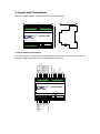
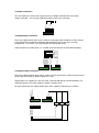
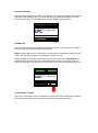
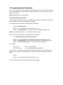
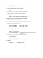
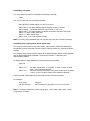
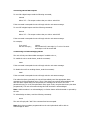
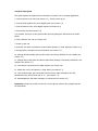
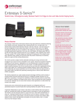
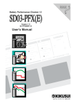
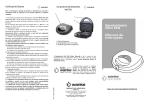
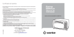
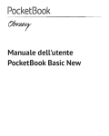
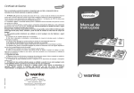
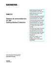
Unit 7/8,
Heathrow Causeway Estate,
Ariel Way, Hounslow
Middlesex, TW4 6JW
+44 (0) 208 6302270
GSM Alarm MK2
GSM Alarm MK 2
User Manual Version 1.00
All rights reserved
The information contained in this manual has been carefully checked and is believed to be
accurate. However, CPC (UK) Ltd assumes no responsibility for any inaccuracies that may be
contained herein. In no event will CPC (UK) Ltd, be liable for any direct, indirect, special,
incidental, or consequential damages resulting from any defect or omission in this manual,
even if advised of the possibility of such damages. In the interest of continued product
development, CPC (UK) Ltd reserves the right to make improvements to this manual, and the
products described herein, at any time without notice or obligation.
Copyright
Copyright by CPC (UK) Ltd. No part of this manual may be reproduced or transmitted in any
Form without express written authorisation from CPC (UK) Ltd.
Trademarks
All trademarks are acknowledged and are the property of their respective holders.
Contents
1.
2.
3.
4.
Copyright ..................................................................................................................... 2
Trademarks .................................................................................................................. 2
Introduction .................................................................................................................. 4
Layout and Connections ................................................................................................ 5
2.1 Screw Terminal Connections .................................................................................... 5
2.2 Power Connection ................................................................................................... 6
2.3 Digital Input Connection .......................................................................................... 6
2.4 Digital Output Connection ........................................................................................ 6
2.5 Ariel Connection ...................................................................................................... 7
2.6 SIM Card ................................................................................................................ 7
2.7 Installation Location ................................................................................................ 7
Programming and Operation .......................................................................................... 8
3.1 Programming phone numbers .................................................................................. 8
3.2 Deleting phone numbers .......................................................................................... 9
3.3 Programming alarm SMS message text ..................................................................... 9
3.4 Reading unit status ............................................................................................... 10
3.5 Setting relay output pulse & alarm repeat delay ...................................................... 10
3.6 Turning ON and OFF outputs ................................................................................. 11
3.7 Receiving and acknowledging alarms ...................................................................... 11
3.8 Quick setup guide ................................................................................................. 12
3.9 SMS Command summary ....................................................................................... 13
Revisions .................................................................................................................... 14
1. Introduction
The GSM Alarm MK2 is a simple alarm monitoring unit, capable of sending alarm messages
via SMS to up to 6 mobile phone numbers.
The unit incorporates a number of digital inputs which can be used to monitor fault signals
from other equipment. When triggered each input will send a different alarm message, alarm
messages can be programmed by the user.
Once an alarm has been triggered, alarm messages must be acknowledged by the user by
sending an acknowledgement SMS message back to the unit. Until an acknowledgement is
received, the unit will keep re-sending the alarm message.
The unit accepts a standard mobile phone SIM card (contract or pay-as-you-go), and is
configured by the user by sending SMS messages to the unit.
2. Layout and Connections
The unit is supplied within a standard DIN rail mounting enclosure,
105
60
GSM Alarm MK2
90
2.1 Screw Terminal Connections
The unit includes 3 x 9 way screw terminal connector blocks, these are used for connection to
the power supply and remote devices for monitoring and control;
12VDC
GND
Digital Input 1
Digital Input 2
Digital Input 3
Digital Input 4
Digital Input 5
Digital Input 6
12VDC (Protected)
NO
Output 3
COM
Relay
NC
GSM Alarm MK2
5VDC (Protected)
Not
Used
GND
Digital Output 4
Digital Output 2
Digital Output 1
2.2 Power Connection
The unit requires a 12VDC power supply, there are multiple terminals where the power
maybe connected – only one pair (GND and 12VDC) need to be connected;
12VDC
GND
2.3 Digital Input Connection
There are 6 digital inputs which can be used for monitoring alarm conditions of other devices.
If the digital input is activated, and alarm SMS message is sent (if the unit is correctly
programmed – see section 3 on programming and operating the unit).
Inputs operate as normally open (i.e. a closed circuit will activate an alarm SMS message);
12VDC
Digital Input 1
Digital Input 2
Digital Input 3
Digital Input 4
Digital Input 5
Digital Input 6
2.4 Digital Output Connection
There are 4 digital outputs which can be used to control other devices. Outputs can be turned
ON and OFF by sending an SMS message to the unit.
Digital output 3 is supplied as a volt-free relay, with both NO and NC contacts available. The
maximum rating for the relay contacts is 24VDC / 240VAC @ 5A.
All other outputs are low voltage Mosfet open drain, capable of switching up to 50VDC.
NO
COM
NC
12VDC
Output 3
Relay
LOAD
LOAD
LOAD
Digital Output 4
Digital Output 2
Digital Output 1
2.5 Ariel Connection
The unit needs a GSM ariel in order for it to operate. The unit can be supplied upon request
with either local (stubby) ariel, or a remote ariel with a 2m cable. Both types of ariel are
connected to the unit via a gold BNC type connector, above the GSM modem.
GSM Alarm MK2
2.6 SIM Card
Ariel Connector
The unit must be fitted with a mobile phone SIM card before it will operate. Any standard
contract or pay-as-you-go SIM card will be suitable.
Note: If using a pay-as-you-go SIM card, you must ensure the SIM card is topped up with
credit – the unit will not report any messages if credit has run out.
Before installing or removing the SIM card, you must ensure the unit is powered off. To
install the card, push it into the slot on the GSM modem, until you feel / hear a click. To
remove the card, push the card until you feel / hear a click – the card should then pop out.
GSM Alarm MK2
2.7 Installation Location
The unit (or remote ariel) must be installed in a location with good mobile phone reception
from the service provider which has supplied the SIM card installed in the unit.
3. Programming and Operation
The unit is programmed by sending SMS command messages to the unit. It is important that
the correct command is sent (as outlined in this manual) by the user; otherwise the unit will
ignore the command.
Note: Commands are not case sensitive
3.1 Programming phone numbers
The unit maybe programmed with up to 6 mobile phone numbers, these phone numbers will
be the numbers which will receive SMS alarm messages.
To program any phone number, send the following command;
SetnnX +NNNNNNNNNNNN
Where “X” = the phonebook entry number from 1 to 6
Where “+NNNNNNNNNNNN” = the phone number including the country code
Note: You must always include a “+” before the number as shown
The unit will reply, confirming the command has been accepted;
X: +NNNNNNNNNNNN-MMMMMMMMMMMMMMM
Where “X” = the phonebook entry number that has been changed from 1 to 6
Where “+NNNNNNNNNNNN” = the actual phone number in that phonebook entry
Where “-MMMMMMMMMMMMMMM” = the network tag for this number
For example;
if you send;
the unit will reply ;
Setnn1 +447799123456
1: +447799123456-C91447799214365”
A user may also enter their own phone number without needing to enter the actual phone
number at all, to do this send the following command from the phone number you wish to
enter;
SetnrX
Where “X” = the phonebook entry number from 1 to 6
The unit will reply with “OK” if the command has been accepted.
3.2 Deleting phone numbers
Before changing any phonebook entry, the old entry must be deleted.
To delete all phonebook entries, send the command;
Clrnr0
The unit will reply with “OK” if the command has been accepted.
To delete a specific phonebook entry, send the command;
ClrnrX
Where “X” = the phonebook entry to be deleted from 1 – 6
The unit will reply with “OK” if the command has been accepted.
3.3 Programming alarm SMS message text
The unit will send different messages for each digital input which is in alarm.
The factory default messages are as follows;
Input 1 = Input_1_Alarm
Input 3 = Input_3_Alarm
Input 5 = Input_5_Alarm
Input 2 = Input_2_Alarm
Input 4 = Input_4_Alarm
Input 6 = Input_6_Alarm
The user may change the alarm messages by sending the following command;
SettxX AAAAAAAAAAAAAAA
Where “X” = the input number
Where “AAAAAAAAAAAAAAA” = The actual message you wish the unit to send (up to
15 Characters)
The unit will reply, confirming the command has been accepted;
X-AAAAAAAAAAAAAAA
Where “X” = the input number
Where “AAAAAAAAAAAAAAA” = The actual message the unit will now send.
For example;
if you send;
the unit will reply ;
Settx1 Gas_Leak_Alarm
1-Gas_Leak_Alarm
3.4 Reading unit status
You can read the unit status by sending the following command;
Getst
The unit will reply with the unit status message;
INP=IIIIII OUT=OOOO SQ:ZZ,Z T=X W=V S=YYYY
Where
Where
Where
Where
Where
Where
IIIII = The input states for inputs 654321, 0=open 1=closed
OOOO = The output states for outputs 4321, 0=off 1=on
Z,ZZ = The signal quality, the higher the number the better the signal
T = Relay output pulse time
V = Alarm repeat delay
YYYY = The units software version
Note : For many other commands the unit may also reply with the unit status message.
3.5 Setting relay output pulse & alarm repeat delay
You setup the relay output to only pulse ON for a few seconds, rather than staying ON
permanently when a command is sent to switch it ON (see section 3.6 Turning ON & OFF
outputs).
You can also setup a delay between repeat alarm SMS messages. Alarms will be repeated
until an acknowledgement command is received (see section 3.7 Receiving and
acknowledging alarms).
To change either of these parameters, send the following command;
SettnA B
Where “A” =
Where “B” =
The alarm repeat delay, 0=no delay, 1=1min, 2=2min..9=9min
(9min is the maximum allowed)
The relay output pulse period, 0=no pulse (output does not pulse),
1=2sec, 2=4sec..9=18sec (18sec is the maximum allowed)
If the command is accepted the unit will reply with the unit status message.
For example;
if you send;
the unit will reply ;
Settn5 0
INP=00000 OUT=0000 SQ:15,0 T=0 W=5 S=0001
Note : The factory defaults are, alarm repeat delay = 5min, relay output pulse = 0min
(output does not pulse)
3.6 Turning ON and OFF outputs
To turn ON a digital output send the following command;
SetouN
Where “N” = The output number that you wish to switch ON
If the command is accepted the unit will reply with the unit status message.
To turn OFF a digital output send the following command;
RstouN
Where “N” = The output number that you wish to switch OFF
If the command is accepted the unit will reply with the unit status message.
For example;
if you send;
the unit will reply ;
Setou1
INP=00000 OUT=0001 SQ:15,0 T=0 W=5 S=0001
and output 1 will be turned ON
3.7 Receiving and acknowledging alarms
The unit will only send alarm SMS messages if enabled to do so,
To enable the unit to send alarms, send the command;
Seten
If the command is accepted the unit will reply with the unit status message.
To disable the unit from sending alarms, send the command;
Setdi
If the command is accepted the unit will reply with the unit status message.
If an alarm has been generated, the unit will immediately send the appropriate alarm
message to the first phonebook entry. Then, if the alarm has not been acknowledged, and
after the alarm repeat delay time has passed, the message will be sent to the next
phonebook entry (or to the first phonebook entry again if only one phonebook entry has been
programmed). The unit will continue doing this until the alarm is acknowledged.
Note : Whilst an alarm is un-acknowledged, no further alarms will be detected or reported by
the unit.
To acknowledge an alarm, send the following command;
Ackno
The unit will reply with “OK” if the command has been accepted.
Note: Only phone numbers programmed into the unit’s phonebook will be able to
acknowledge an alarm.
3.8 Quick setup guide
This guide explains the steps that must be taken to setup a unit for a typical application;
1. Connect power to the unit (see section 2.2) – do not power up yet.
2. Connect fault signals to the unit’s digital inputs (see section 2.3)
3. Connect devices to the unit’s digital outputs (see section 2.4)
4. Connect the ariel (see section 2.5)
5. If possible, check you a have good mobile signal by putting the SIM card into a mobile
phone.
6. Fit the SIM into the unit (see section 2.6)
7. Power up the unit
8. Send the unit status command to confirm basic operation, ie send Getst (see section 3.4)
9. Program phone numbers into the phonebook (see section 3.1)
10. Change default message text for each input if the factory defaults are not suitable (see
section 3.3)
11. Change relay output pulse and alarm repeat delay settings if the factory defaults are not
suitable (see section 3.5)
12. Test devices connected to the digital outputs (see section 3.6)
13. Enable the unit to send alarms, ie send Seten (see section 3.7)
14. Test an alarm input, the unit should send the correct alarm message to the first
phonebook entry, second entry and so on… (see section 3.7)
15. Acknowlegde the test alarm message, ie send Ackno (see section 3.7)
Important : Please be careful to ensure the correct phone numbers are programmed into
the phonebook.
3.9 SMS Command summary
Command
Getst
Function
Gets unit status
Setou1
Setou2
Setou3
Rstou1
Rstou2
Rstou3
Seten
Setdi
Settx1 text
…
Settx6 text
Setnn1 +number
…
Setnn6 +number
Setnr1
…
Setnr6
Clrnr0
Clrnr1
…
Clrnr6
SettnA B
Ackn0
Set output 1
Set output 2
Set output 3
Reset output 1
Reset output 2
Reset output 3
Enable alarms
Disable alarms
Write SMS alarm text
…
Write SMS alarm text
Set phonebook entry 1
…
Set phonebook entry 6
Set phonebook entry 1
…
Set phonebook entry 6
Clear phonebook
Clear phonebook entry 1
…
Clear phonebook entry 6
Set timers
Alarm Acknowledge
Description
Returns digital input & output states, signal quality, timer
settings and software version
Turns ON digital output 1
Turns ON digital output 2
Turns ON digital output 3
Turns OFF digital output 1
Turns OFF digital output 2
Turns OFF digital output 3
Enables the unit to send SMS alarm messages
Disable the unit from sending SMS alarm messages
Changes alarm text for digital input 1
…
Changes alarm text for digital input 6
Sets phonebook entry 1 to number send in message
…
Sets phonebook entry 6 to number send in message
Sets phonebook entry 1 to originating phone number
…
Sets phonebook entry 6 to originating phone number
Deletes all numbers stored in the phonebook
Deletes the number stores at phonebook entry 1
…
Deletes the number stores at phonebook entry 6
Sets the alarm repeat timer, and relay output pulse timer
Acknowledges the SMS alarm message
4. Revisions
This manual has been based around software version 0001.
Revision
0001
Date
27/02/2009
Changes
First release