1
Basic Instructions
Basic Instructions
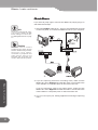
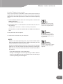
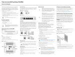
DIGITAL IN mode
Outputs converted
Analog signal.
DIGITAL IN LED is lit.
Info
There are few PC that can control
multiple devices, do not use the
ADVC110 in the Hub connection
where multiple DV signals are
input simultaneously).
Inputs DV signal either
from the 4 pin connector
on the front panel or the
6 pin connector on the
rear panel.
Input Analog signal is
ignored.
How to switch modes
ANALOG IN mode
Pr
Press the STOP or the REC (REC PAUSE)
button of the deck control interface
on the capturing application.
es
st
he
IN
PU
T
Press the PLAY (PLAY PAUSE)
button of the deck control interface
on the capturing application.
SE
LE
CT
bu
tto
n
DIGITAL IN mode
Basic Instructions
Basic Instructions
12
12
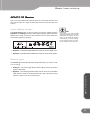
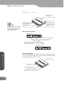
Color Bar Output
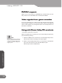
Press and hold the INPUT SELECT button for three seconds to output
color bars from the Analog output. Input Analog and Digital signals
are ignored, while the audio is muted.
Outputs color bars.
Both LEDs are lit.
Input Analog signal is ignored.
Input Digital signal is ignored.