1
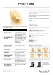
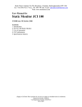
Timpdon
Electronics
Crossing Controller Model XC1
User Manual
Features
•
•
•
•
•
•
•
•
•
•
Fully automatic control of both gated and rising barrier
crossings.
Up and down lines, single and dual track.
Up to four independently controlled gates or barriers.
Home and distant signals on both lines.
Flashing visible and audible warnings.
Designed for use with Timpdon Electronics ServoSwitches Model
SCS1.
Fully User programmable.
Custom PC program for setting of operating parameters and
timings, and for real time monitoring of crossing operation.
Can be operated manually using push b utton switches, or by
approaching train, using track mounted reed switches.
4.8V to 6V d.c. supply.
Introduction
The XC1 crossing controller is designed to implement fully automatic control of almost any
type of level crossing with the minimum number of components.
The XC1 itself provides accurately timed, user programmable output triggers for precise
control of level crossing gates or barriers and associated signals and audible and visual
warnings, to give exact prototypical operation.
The actual movement of gates and signals is performed by Timpdon Electronics ServoSwitches
Model SCS1 and associated servo motors, which must be purchased separately.
User programming of the XC1 is performed using a desktop or laptop PC and a custom PC
program supplied with the XC1. The PC communicates with the XC1 via a standard serial
communications link.
In addition, the PC program incorporates a passive monitor function which allows the
complete status of the crossing control process to be viewed in real time on the PC, with the
crossing in normal operation, without affecting the actual operation of the controller.
The XC1 is supplied complete with a CD ROM containing the custom PC program and copies
of all manuals and relevant Technical Notes in .PDF format.
In addition, a 1.5 metre serial communications cable is included for direct connection
between the XC1 and the PC. For users whose PC does not incorporate an external serial
connector, Timpdon Electronics can supply a USB to Serial adaptor, Model XC1-USB which
allows the XC1 to be operated from any available USB port on the PC.
Timpdon Electronics
Tel
EMail
0161 - 980 7804
[email protected]
Issue 2 – October 2010
Page 1 of 5
XC1 Crossing Controller – User Manual
Connections
XC1
G3
G4
UH
UD
DH
DD
Timpdon
Electronics
Crossing
Controller
Model XC1
S2
S3
Connections to
Control Switches
S4
Visual
Audible
+5V
Signals
Connections to
Signal
ServoSwitches
S1
Warn
G2
Output
Crossing Gates
Control Switches
G1
Connections to
Crossing Gate
ServoSwitches
0V
Program
+4.8 to 6V
0V
Connections to
Audible and Visual Warnings
Power to External Components
Maximum Permissible Load = 30 mA
Program Mode
Push Button
Power Supply
4.8 to 6V D.C.
Serial Cable to PC
Notes
1
The diagram above shows only the basic connections to the XC1. For detailed examples
of wiring diagrams for a number of different crossing control systems, refer to
Technical Note 13 – Wiring Diagrams for Crossing Controller Model XC1.
2
The XC1 is designed to be controlled using momentary switches, either two momentary
on-off-on toggle switches or four individual push button switches.
Alternatively, for automatic vehicle triggered operation, track mounted reed switches
and vehicle mounted magnets may be substituted.
The actual switch function for each of the four control switches varies depending on the
layout configuration. Refer to Technical Note 13.
3
Trigger outputs to the individual crossing gate ServoSwitches have the following levels:
Gate Open
Gate Closed
4
= Road Traffic
= Rail Traffic
+5V
0V
Trigger outputs to individual signal ServoSwitches have the following levels:
Reset
Set
= Danger
= Clear
+5V
0V
For layouts with colour light signalling, colour light signals can be powered directly from
the signal outputs of the XC1, using LEDs with external series resistors. The maximum
current drawn from each signal output must not exceed 10 mA.
Timpdon Electronics
Tel
EMail
0161 - 980 7804
[email protected]
Issue 2 – October 2010
Page 2 of 5
XC1 Crossing Controller – User Manual
5
Trigger outputs to both the audible and visual warnings have the following levels:
De-energised
Energised
0V
+5V
For Audible warnings, a small piezo electric sounder is recommended. Timpdon Electronics
Model XC1- SND is suitable.
For Visual warnings, LEDs with external series resistors are ideal.
The maximum load current on each of the warning outputs must not exceed 10 mA.
6
The XC1 is designed to be used with supply voltages from 4.8 to 6V D.C. only. Although
both the XC1 and associated ServoSwitches SCS1 will accommodate higher voltages,
the servos providing the motive power for crossing gates and semaphore signals may
be irreparably damaged if subjected to supply voltages higher than 6V.
Crossing Controller Functions
The XC1 can be user configured to accommodate almost any crossing system to suit any
layout. There are 23 separate functional and timing parameters which can be user
programmed, as required. Many of the available functions can be enabled or disabled, to
suit the layout.
You are recommended to study the following additional manuals carefully before starting to
design and configure a crossing for your layout.
•
XC1 PC User Manual
•
Technical Note 13 – Wiring Diagrams for Crossing Controller Model XC1
•
Technical Note 14 – Timing Diagrams for Crossing Controller Model XC1
All of these manuals are included, in .PDF format, on the CD ROM supplied with the XC1.
For a completely installed four gate crossing system, with full signalling, the actions taken
by the XC1, following Close Gates and Open Gates requests are detailed below:
Close Gates
1
Energise audible and visual warnings and wait for the Gate Close Warning Period
to expire.
2
In turn, trigger gate closure on each of the four gates, with individually
programmed Gate Close Delays for each gate.
3
Wait for completion of the Gate Closing Period to permit all gates to reach the
fully closed position.
4
Silence the audible warning.
5
Wait for the expiry of the Home Signal Delay Period and then clear the Home
signal.
6
Wait for the expiry of the Distant Signal Delay Period and then clear the Distant
signal.
Timpdon Electronics
Tel
EMail
0161 - 980 7804
[email protected]
Issue 2 – October 2010
Page 3 of 5
XC1 Crossing Controller – User Manual
7
Wait for the expiry of the Minimum Gates Closed Period, before acting upon any
subsequent Gate Open request.
Open Gates
1
Set the Distant signal to danger and wait for the expiry of the Distant Signal
Delay Period.
2
Set the Home signal to Danger and wait for the expiry of the Home Signal Delay
Period.
3
Energise the audible warning and wait for the expiry of the Gate Open Warning
Period.
4
In turn, trigger gate opening on each of the four gates, with individually
programmed Gate Open Delays for each gate.
5
Wait for completion of the Gate Opening Period to permit all gates to reach the
fully open position.
6
Silence the audible warning and extinguish the visual warning.
7
Wait for the expiry of the Minimum Gates Open Period, before acting upon any
subsequent Gate Close request.
Crossings With Overlapping Gates
The XC1 is designed to permit the use of crossings with overlapping gates, where the
motion of the gates must be staggered in both the closing and opening directions to avoid
interference between gates when in motion.
In such a situation, however care must be taken to avoid a conflict when power is applied to
the control system, to ensure that all gates do not attempt to reset to either the open or
closed condition at the same time, resulting in a gate clash.
To minimise this risk, both the XC1 and SCS1 units are designed to remember the last
position in which the gates were set [open or closed] before power was removed, and will
automatically reset to that state when power is next applied to the control system.
To ensure that this informatio n is correctly saved, you must ensure that you do not power
down the crossing control system unless the gates are in the fully open or fully closed
positions. If you power down whilst the gates are in motion, the system will be unable to
determine the correct state in which to reset the control system on power up, and a gate
clash may occur on the next application of power.
If this happens, as the servos used for gate movement are quite powerful, mechanical
damage to the gates may occur.
For further protection, you may wish to consider additional me asures:
•
Design each crossing gate with a friction fit only on to its servo drive shaft, so that
it will disengage if excessive force is applied.
•
Fit a fast acting resettable thermal fuse [Polyswitch] in the positive supply to each
SCS1 used for crossing gate control. A fuse with a continuous current rating of
about 100 mA should be suitable [e.g. - Tyco Electronics Part RXEF010].
Timpdon Electronics
Tel
EMail
0161 - 980 7804
[email protected]
Issue 2 – October 2010
Page 4 of 5
XC1 Crossing Controller – User Manual
Accessories
The following accessories are available from Timpdon Electronics, for use with the XC1:
o
XC1-USB
USB to Serial communications adaptor
For PCs without external serial ports
o
XC1-SND
Small piezo electric sounder for audible warning
Connects directly to XC1
o
XC1-TK
Track
-
o
SCS1
ServoSwitch, complete with servo
One required for each crossing gate or signal
Timpdon Electronics
Operation Kit
Pack of two pre-wired reed switches and one magnet
Permits automatic crossing operation by moving vehicle
See Technical Note 13 to determi ne number required for
your layout
Tel
EMail
0161 - 980 7804
[email protected]
Issue 2 – October 2010
Page 5 of 5