1
INFRAPLEX 2005
Infrared Simultaneous Interpretation System
User Manual
DIGITON Ltd.
INFRAPLEX 2005
Infrared Simultaneous Interpretation System
Copyright
All rights reserved!
None of the parts of the User Manual can be copied, forwarded or translated without the
written permit of the author (DIGITON Ltd.).
Printed in Hungary
February, 2008
Version: 1.8
2/45
Contents
1.
GENERAL INFORMATION ....................................................................................................4
1.1. INTRODUCTION ................................................................................................................ 4
1.2. GENERAL SYSTEM CHARACTERISTICS ............................................................................. 4
1.3. INTERPRETATION TECHNICAL SYSTEMS AND APPLICATIONS ............................................ 6
1.3.1. System with one relay interpreter ............................................................................6
1.3.2. System with chains of interpreters...........................................................................6
1.3.3. System with one relay language ..............................................................................6
1.3.4. System with several relay languages .......................................................................6
2.
SYSTEM ELEMENTS................................................................................................................8
2.1. CENTRAL UNIT PEP 3001................................................................................................ 8
2.1.1. General introduction ...............................................................................................8
2.1.2. Operation guide .....................................................................................................11
2.1.3. Power supply .........................................................................................................13
2.1.4. System arrangement and control ...........................................................................13
2.1.5. DIP switches ..........................................................................................................13
2.1.6. Technical data .......................................................................................................14
2.1.7. Connectors.............................................................................................................15
2.2. CHANNEL DECODER PEP 3006 ...................................................................................... 17
2.2.1. General introduction .............................................................................................17
2.2.2. Operation guide .....................................................................................................19
2.2.3. Technical data .......................................................................................................20
2.2.4. Connectors.............................................................................................................20
2.3. INTERPRETER UNIT HEP 303 ......................................................................................... 21
2.3.1. General introduction .............................................................................................21
2.3.2. Operation guide .....................................................................................................21
2.3.3. Preparatory steps for programming the interpreter unit ......................................25
2.3.4. Programming the interpreter unit when interpreters work alone (single mode) ..26
2.3.5. Programming the interpreter unit in the case of interpreters working in pairs
(twin mode)........................................................................................................................28
2.3.6. Using the interpreter unit ......................................................................................29
2.3.7. Technical data .......................................................................................................31
2.3.8. Connectors.............................................................................................................31
2.4. INFRARED RADIATORS AYP 3001 AND AYP 3002........................................................ 32
2.5. INFRARED RECEIVER UNIT AYP 307.............................................................................. 34
2.6. CHARGING-STORING CASE ETT 350 .............................................................................. 37
3.
PLACING, CABLING AND SETTING UP THE UNITS OF THE SYSTEM...............39
4.
CO-OPERATION WITH CONFERENCE SYSTEM ICN 2005 ......................................43
3/45
1. GENERAL INFORMATION
1.1. INTRODUCTION
INFRAPLEX 2005 infrared simultaneous interpretation system (Diagram 1) is the
indispensable technical background equipment of multi-lingual meetings, conferences. The
voice of the interpreters, is forwarded from the microphone of the interpreter unit through the
central unit of the system to the relevant language channels with the aid of infrared radiation
to the infrared receiver units to the participants.
The language or floor voice selected with the aid of the channel selector can be heard
through the headphone that is connected to the receivers. Its volume can be set with the aid of
the volume regulator of the unit. Thanks to the size of the receiver and infrared signal, the
system allows not only free sitting order and mobility during the meeting, but it also provides
protection against unauthorised eavesdropping efforts as well.
The simple cabling of the system and the mechanical design of the units are
advantageous for both mobile arrangements and fixed installations. Configuring,
programming the interpreter units is technically simple, the management and the display
system of the interpreter units are ergonomic and fully compliant with the international
standards.
1.2. GENERAL SYSTEM CHARACTERISTICS
The core equipment of the system is the central unit PEP 3001. The external analogue
devices dealing with floor loudening (e.g. microphone, mixer, amplifiers, loudspeakers) and
the units that take care of voice recording and playing back are connected to this central unit.
The analogue devices are connected through standard connecting interfaces and levels, with
traditional (point-to-point) cabling.
The internal wired units of the system - the AYP 3001, AYP 3002 infrared radiators and
the HEP 303 interpreter units – are connected to the central unit through chain-like (series)
concatenation. The infrared radiators communicate with central unit PEP 3001 through a
coaxial wire, while the interpreter units communicate with the core equipment through 4x2
twisted twin-wires. The output connector of the last – serially concatenated - interpreter unit
must be closed by a closing element in all the cases.
The infrared radiators have radiation characteristics of an opening angle of 60° with a
cone-like start, the axis direction effective range of the radiators is either 90 m (in the case of
unit AYP 3001) or 140 m (in the case of unit AYP 3002). In the general set-up the radiated
space is 250-450 m3 in the case of unit AYP 3001 and 450-700 m3 in the case of unit AYP
3002. Naturally the sound reflecting and damping properties of the room may significantly
influence these radiation characteristics.
The participants may select from 7 audio channels with the aid of infrared receivers
AYP 307, which means 6 interpreted languages and the floor voice. The floor voice can be
always heard on channel 0, while the numbering of the rest of the language channels
corresponds to the language numbering configuration of the interpreter units.
An important accessory of the system is charging-storing case ETT 350, which ensures
on one hand the storing and transportability of the 50 infrared receivers, and on the other hand
it also takes care of the charging of the 9 V Ni-MH accumulators inserted into the receivers.
4/45
Diagram 1 – Overview drawing of the arrangement of the elements of interpreter system
INFRAPLEX 2005
5/45
1.3. INTERPRETATION TECHNICAL SYSTEMS AND APPLICATIONS
The interpretation system with its incorporated controlling automatic mechanisms,
managing and displaying interfaces is suitable for implementing different types of
interpretation logical arrangements. These may be the following:
1.3.1. System with one relay interpreter
The basis of the system is the relay interpreter (Interpreter 1), who is able to translate
from all the possible speaker languages of the conference to a common selected "relay"
language, from which the rest of the interpreters interpret for the participants (Diagram 2.a).
From the aspect of the interpreters the units do not have to be managed and the output does
not have to be changed, if there is no speaker speaking the relay language. In the case of a
"relay" language speech, the output of the relay interpreter has to be switched to the relay
language speaker. The arrangement is simple, the interventions are minimal, in spite of this,
this system is rarely used, because it raises high demands as regards the relay interpreter.
1.3.2. System with chains of interpreters
The logical connection of the interpreters is established through the common languages
(Diagram 2.b). To one common language 2 interpreters are connected. In the case of a speech
kept in an other language than the required one, by switching the input channels or the "relay"
the interpreter executes direct translation from one of the common languages. The system in
spite of its seemingly simple arrangement demands from the interpreters certain kind of
management skills and several interventions, and the final setting time strongly depends on
the manual connecting reactions.
1.3.3. System with one relay language
This most frequently used logical structure is shown on Diagram 2.c. In this case the
interpreters are selected in such a manner, that each has to know a common language that is
known by the others as well. This is generally the mother tongue of the country that hosts the
conference, since finding mother tongue speaking interpreters is usually the easiest. The
common connecting language is the "relay" language or channel. It is sufficient if the
interpreters switch the input languages in the configured system between the "floor voice" and
the "relay" channel, and to set the output. The period needed for logically setting up the
system is short, and the management tasks of the interpreters are simple.
1.3.4. System with several relay languages
It can be interpreted as the combination of the chain (2.b) and the relay (2.c)
arrangements also, since several interpreters are connected to several relaying languages (See
Diagram 2.d). In the case of this version it is needed to manually switch between the inputs
and the "relay", and to manually switch the output. It needs increased attention both in the
course of configuring and in the course of management.
6/45
Diagram 2 – Technical systems for interpretation
7/45
2. SYSTEM ELEMENTS
2.1. CENTRAL UNIT PEP 3001
2.1.1. General introduction
Central unit PEP 3001 is the core element of interpretation system INFRAPLEX 2005,
and it has to be included in all the configurations. It is the task of the unit to synchronise the
system and to generate the floor voice. One PEP 3001 unit can manage maximum 400
participant and interpreter units, with the relevant system arrangement. Through the analogue
inputs of the unit it is also possible to mix the signals of external audio sources to the floor
voice, and from its outputs it is possible to forward the signal of the floor voice channel to an
external amplifier or to a voice recording equipment. There are two coaxial outputs on the
device, which are for driving the infrared radiators.
The central unit, in addition to the above, controls speech selection, voting and indicates
the "SLOWLY PLEASE" request of the interpreters to the speakers The central unit manages
also the "waiting list", including the units withouth free channels.
When a busy channel is freed, the first unit of the waiting list is included among the
units that got the word.
However, it has to be noted, that the functions mentioned in the previous paragraph
operate only if the delegate units of conference system ICN 2005 are also connected to the
system.
Diagram 3 of the next page contains the overview drawing of unit PEP 3001.
8/45
Diagram 3 – Overview drawing of central unit PEP 3001
9/45
The following table contains the functions and the role of those managing and
displaying tools, and the connectors of central unit PEP 3001 that are marked in Diagram 3.
Number
1
2
3
4
5
6
7
8
9
10
11
12
13
14
15
16
17
18
19
20
21
22
23
24
25
26
27
28
29
10/45
Name
„SYSTEM” – volume regulator of the system
„LINE” – volume regulator of the line level input
„EXT. MIC.” – volume regulator of the external microphone input
„TAPE” – volume regulator of the tape recorder input
„TELEPHONE” – volume regulator of the phone input
„LANG. EXT.” – volume regulator of the external language input
„NOM LIMIT” – switch for setting the number of microphones that
may be switched on simultaneously
„SPEAKERS” – volume of the signal that goes to the loudspeakers of
the units
Outgoing control meter of the signal that goes to the loudspeakers that
are incorporated into the units
„MAIN” – volume regulator of the line level output
Outgoing control meter of the line level output
„HEADPHONE” – volume regulator of the headphone output
Status indicating LEDs
Headphone connector
„POWER” – supply voltage main switch (it has a function only when
ETP 315 is used)
„DC 30V” – supply voltage connector for connecting unit ETP 315)
„SYSTEM 1” – system connector
„SYSTEM 2” – system connector
„INFRA OUT” – coaxial outputs to the infrared radiators
„TAPE OUT” – output for a voice recording device
„TAPE IN” – input for a voice recording device
„EFFECT OUT” – output for connecting an external device
„EFFECT IN” – input for connecting an external device
„EXT. LANG. IN” – connector of external language input
„TEL. OUT” – connector of phone output
„TEL. IN” – connector of phone input
„LINE OUT” – connector of line level output
„LINE IN” – connector of line level input
„EXT. MIC. IN” – input connector of external microphone
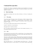
2.1.2. Operation guide
Starting up the operation of the central unit – after connecting power unit ETP 315 – is
done with switch marked „POWER” (15), which is indicated by led marked „POWER” (13)
of the device. After switching on, LEDs „REMOTE” and „NOM LIMIT” (13) flash
alternatively on the front panel of the central unit for some seconds – during the period of
synchronising –, then after completing synchronisation both go out.
During operation the flashing of LED marked „REMOTE” (13) indicates data
transmission, while the flashing of LED marked „NOM LIMIT” (13) indicates a
synchronisation error.
Unit PEP 3001 also contains a 6 channel analogue mixer, the block scheme of which is
presented in Diagram 4 on the next page. The signal entered through the inputs of the mixer
(„SYSTEM”, „LINE”, EXT. MIC.”, „TAPE”, „TELEPHONE”) can be mixed to the
collecting bar ("NORMAL BUS") of the floor voice with volume regulators (1-5) that belong
to these inputs. The Floor Voice generated this way on one side is forwarded to channel 0 of
the PPM modulator of the unit, and on the other side it appears on outputs marked „LINE
OUT” (27) and „TAPE OUT” (20) of the device.
The volume regulator of mixer marked „SYSTEM” (1) regulates the aggregated signal
of the switched on microphones of the conference system, which signal is subsequently
forwarded to the collecting bar ("NORMAL BUS") of the floor voice. The level of the floor
voice signal ("FLOOR") that is forwarded from here to the built-in loud-speakers of the
conference system can be regulated with volume regulator marked „SPEAKERS” (8). The
level of the signal forwarded to the loudspeakers – that may be controlled with control meter
(9) located next to the regulator – has to be set in such a manner that the red colour LED
should flash only for a short while even in the case of louder voices.
The level of the floor voice signal appearing on output marked „LINE OUT” (27) can
be set to the value desired with the volume regulator marked „MAIN” (10) located on the
front panel, and this can be also visually checked on the control meter (11) that is located next
to the regulator. The level of the outgoing signal has to be set in such a manner, that the red
colour LED of the control meter should flash for a very brief time only in the case of each
loud voice, and it should not be lit continuously. This output can be used for controlling the
floor loudspeakers of the given room.
With the aid of the headphone connected to the headphone socket (14) of the front
panel, the floor voice ("FLOOR") can be checked acoustically as well. The volume of the
signal forwarded to the headphone can be set to the desired value with the aid of the volume
regulator "HEADPHONE" (12) that is located next to the connector.
The central unit is capable of receiving external phone lines as well. However, a special
connecting cable is needed for this, prepared for this purpose. The signal that goes to the
headphone of the handset of the phone device has to be introduced to input „TEL. IN” (26) of
unit PEP 3001, the volume of which can be set with volume regulator marked
„TELEPHONE” (5). And the signal of the microphone output marked „TEL. OUT” (25) of
the central unit has to be introduced to the input of the handset of the receiving phone device.
It is also possible to mix the input signals of PEP 3001 to an „EFFECT BUS", and from
the „EFFECT BUS" to forward the mixed signal to an external unit (e.g. feedback supressor)
through connector „EFFECT OUT” (22). The signal given out to the external unit can be reentered into the central unit with the aid of connector „EFFECT IN” (23).
11/45
Vcc
EFFECT BUS
NORMAL BUS
FLOOR
DIRECT/ TELEPHONE BUS
TAPE OUT
-10dBV
MAIN adj.
NORMAL (OFF)
-40dBV
EXT.MIC. adj.
2. DIP
EFFECT (ON)
HEADPHONES
adj.
0dBV
LINE adj.
LINE OUT
SPEAKERS
adj.
NORMAL (OFF)
0dBV
1. DIP
EFFECT (ON)
Digitally controlled
by NOM. ATT.
A
D
SYSTEM BUS
0dBV
HEADPHONES
TEL. adj.
TEL. OUT
0dBV
0dBV
EFFECT OUT
0dBV
NORMAL (OFF)
-10dBV
TAPE adj.
CH0
3. DIP
EFFECT (ON)
INFRA OUT
D
A
A
NORMAL (OFF)
SYSTEM adj.
D
4. DIP
EFFECT (ON)
CH1
CH2
CH3
CH4
CH5
CH6
PPM modulator
INFRA OUT
CH1-CH6
A
D
INSERT control
0dBV
EXT.LANG. adj.
CH1
Diagram 4 – Block scheme of the analogue part of central unit PEP 3001
12/45
The volume level of the external language entered into input marked „EXT. LANG. IN”
(24) can be set to the desired value with volume regulator marked „LANG. EXT.” (6). The
signal connected here appears on language channel 1, if this function is switched on with DIP
switch 7 located at the bottom of the device.
Information related to the other cables that are to be connected to unit PEP 3001
(system cable and coaxial cable) is included in Section 3.
2.1.3. Power supply
The power supply voltage of the system is ensured by the following power units:
When using unit ETP 315, the power supply voltage gets into the system through central
unit PEP 3001, the power supply voltage provided this way ensures the power supply of
maximum 15 units through 2 different branches.
In the case of unit ETP 370 the power supply voltage goes directly to the system cable,
which ensures the power supply of maximum 70 units through maximum 3 branches.
With using several ETP 370 units it is possible to establish a system that consists of
maximum 400 units.
2.1.4. System arrangement and control
Only one PEP 3001 unit can be used in the system. The PEP 3001 central unit has two
system cable connectors („SYSTEM 1” and „SYSTEM 2”), which allows the installation of
the units on two branches. Both branches have to be continuous and neither can be made up of
only the own elements of system INFRAPLEX 2005 and their connecting cables.
The PEP 3001 central unit is capable of executing the following basic controlling tasks
itself:
The number of simultaneously switched microphones can be set („NOM LIMIT”)
2 different automatic word giving methods can be selected
Managing voting started by the Chairman
Controlling the infra-modulator
2.1.5. DIP switches
The DIP switches located at the bottom of the device and their functions are included in
the following table.
Number of
the switch
1
2
3
4
5
6
7
8
Name
LINE IN
EXT. MIC. IN
TAPE IN
SYSTEM BUS IN
SYSTEM BUS OUT
LINE OUT
EXT. LANG.
Word giving method
Switch setting
Off
for „NORMAL BUS”
for „NORMAL BUS”
for „NORMAL BUS”
for „NORMAL BUS”
NOM damping off
NOM damping off
Switched off
Automatic 1
On
for „EFFECT BUS”
for „EFFECT BUS”
for „EFFECT BUS”
for „EFFECT BUS”
NOM damping on
NOM damping on
Switched on
Automatic 2
13/45
The names included in the above table have the following meanings:
„NORMAL BUS”/„EFFECT BUS”
It can be selected with DIP switches of serial numbers 1–4 in such a manner that the
signals of inputs „LINE IN”, „EXT. MIC. IN”, „TAPE IN” and „SYSTEM BUS IN” should
be forwarded to either the „NORMAL BUS” or the „EFFECT BUS”.
NOM damping:
If it is switched on, then it changes the volume of the loudspeakers of the delegate units
depending on the number of active microphones, in order to avoid acoustic pop noise (as the
number of active microphones increases it reduces the volume of the loudspeakers of the
delegate unit). With switch 5 this attenuation is introduced on output marked „SYSTEM BUS
OUT” that is at the signal that is forwarded to the built-in loudspeakers of the delegate units,
while with switch 6 for example NOM attenuation can be activated on output „LINE OUT”
(27) that is for amplifying the floor voice.
EXT. LANG:
When DIP switch 7 is switched on, the signal forwarded to input connection marked
„EXT. LANG. IN” (24) is introduced to channel 1 of the system, while if it is switched off,
then channel 1 can be used for the interpreted languages.
Word giving methods
With DIP switch 8 it is possible to select from the following two different ways of
giving the word:
Automatic 1:
The microphone of the word asking participant is immediately and automatically
switched on, if there is an available free channel within the system. Otherwise, if there is a
lower priority speaker, then the word will be taken away from the that lower priority speaker,
which has talked for the longest, and in the rest of the cases the word asking participant is
introduced into the waiting list.
Automatic 2:
The microphone of the word asking participants is immediately and automatically
switched on, if there is a free channel available within the system. Otherwise, if there is an
identical or lower priority speaker, then the word is taken away from the one that has talked
for the longest, and in the rest of the cases the word asking participant is introduced into the
waiting list.
2.1.6. Technical data
Height
Width
Depth (with connectors)
Mass
14/45
:
:
:
:
44 mm (1 HE)
482 mm (19”)
108 mm
1450 g
Parameter
DC parameters
Power voltage
Power uptake
Inputs parameters
„LINE IN” input level
„LINE IN” impedance
„TELEPHONE IN” input level
„TELEPHONE IN” impedance
„EFFECT IN” input level
„EFFECT IN” impedance
„TAPE IN” input level
„TAPE IN” impedance
„EXT. LANG IN” input level
„EXT. LANG IN” impedance
„EXT. MIC. IN” input level
„EXT. MIC. IN” impedance
„EXT. MIC. IN” input noise level
to the value desired with an 150 Ώ
drive (E.I.N.)
Outputs parameters
„LINE OUT” output level
„TELEPHONE OUT”output level
„EFFECT OUT” output level
„TAPE OUT” output level
Load impedance for outputs
Relation of signal-noise at the
outputs (EXT. MIC. volume
reduced)
Frequency range (-3dB)
Headset output parameters
Power
Load impedance
Frequency range (-3dB)
Signal-noise ratio
Minimum Nominal Maximum Measurement
unit
16
3
48
-
55
4
V
W
-
0
20
0
20
0
20
-10
20
0
20
-40
20
+6
+6
+6
-4
+6
-34
-
dBu
kOhm
dBu
kOhm
dBu
kOhm
dBu
kOhm
dBu
kOhm
dBu
kOhm
-
-124
-
dBu
-
0
0
0
-10
1
+6
+6
+6
-4
-
dBu
dBu
dBu
dBu
kOhm
88
90
-
dB
20
-
20000
Hz
8
45
70
90
32
-
200
22000
-
mW
Ohm
Hz
dB
2.1.7. Connectors
Power supply voltage
Type of connector: DC power connector
Number of contacts
Function
1
VCC
2
GND
15/45
Audio frequency inputs and outputs
LINE IN, TEL. IN, EXT. LANG. IN, EXT. MIC. IN
Type of connector: XLR socket
Number of contacts
Function
1
GND
2
Audio 3
Audio +
LINE OUT, TEL. OUT
Type of connector: XLR plug
Number of contacts
1
2
3
Function
GND
Audio Audio +
EFFECT IN, EFFECT OUT
Type of connector: 6.3 mm stereo jack socket
Number of contacts
Function
1
GND
2
Audio 3
Audio +
TAPE IN, TAPE OUT
Type of connector: RCA socket
Number of contacts
1
2
Function
GND
Audio
HEADPHONE - headset connector
Type of connector: 6.3 mm stereo jack socket
Number of contacts
Function
1
GND
2
Right
3
Left
System cable connector
SYSTEM 1, SYSTEM 2
Type of connector: D-SUB9 socket
Number of contacts
Function
1
GND
2
CAN+
3
VCC
4
CAN5
GND
6
Returning Digital data +
7
Returning Digital data 8
Forwarded Digital Data +
9
Forwarded Digital Data 16/45
Coaxial cable connector
INFRA OUT
Type of connector: BNC
Number of contacts
1
2
Function
PPM data signal
GND
2.2. CHANNEL DECODER PEP 3006
2.2.1. General introduction
The task of the channel decoder PEP 3006 is to decode all the 31 digital channels of the
INFRAPLEX 2005 interpreter system into the analog format. The unit asures this way the
possibility of listening and recording simultaneously all translated languages. The languages
appear in RCA connectors marked “CH0-CH30” on the backboard of the unit in analog
format. Tape recorder and multichannel digital soundrecorder can be connected to these lines
level sound frequency outputs.
Aditionaly there is an analog line output “EXT LINE”on wich the preset channel can be
selected.
Using the connected headphones the channels of the system can be checked
acoustically.
The power supply of PEP 3006 is assured via system cables, it is not demanded another
external power supply source.
Important! For an adequate working the channel decoder has to be connected to the
„SYSTEM 2” plug of PEP 3001 basic unit.
One of the possible configurations of the system is showed in diagram 11, section 3.
The channel decoder is built in a standard house (as the basic unit) to be inserted in
rack case.
The diagram 5 on the next page shows the overview drawing of channel decoder PEP
3006.
17/45
Diagram 5 - Overview diagram of channel decoder unit PEP 3006
18/45
The following table contains the name and function of those operator and display
components and connectors of channel decoder PEP 3006, which are marked in Diagram 5.
Number
Name
1
„ACTIVE CHANNELS” –green LED indicating the active channel
2
„EXT. LINE SELECT” – external line channel selecting ”down”
button
3
„HEADPHONE SELECT” – headphones channel selecting
”down”button
4
5
External line („EXT. LINE”) two digits channel number display
Headphones („HEADPHONE”) two digits channel number display
6
„HEADPHONE SELECT” – headphones channel selecting ”up”
button
7
„EXT. LINE SELECT” – external line channel selecting ”up” button
8
„HEADPHONE” – volume regulator of the headphones output
9
„POWER” –green LED indicating switched on status
10
11
Headphones connector
„SYSTEM 1” – system connector (plug)
12
„SYSTEM 2” – system connector (socket)
13
„CH0 – CH30” – sound analog output
14
„EXT. LINE” – external line output
2.2.2. Operation guide
Similary to the other units of the system, the connection of the PEP 3006 is possible
with dasy chain of the system cable via the „SYSTEM 1” and „SYSTEM 2” connectors. The
only main difference is that the PEP 3006 has to be connected directly to „SYSTEM 2” output
of PEP 3001.
After swiching on the system, a green „POWER” LED (9) on the front side of the unit
shows the swich on status.
The green „ACTIVE CHANNELS” LED (1) on the left part of the front side of the unit
shows the active channels used momently.The channels used by interpreter and delegate units
are displayed at the same time.
The volume of the headphones connected to the headphone output (10) on the right part
of the unit can be set to the adequate level with volume regulator of the output (8). By
pressing up and down the headphones channel selector buttons (3) and (6) marked
“HEADPHONES SELECT” is possible to listen the desired channel. The number of the
selected channel is visible on the two digits display, between the two press-buttons (5).
The signal wich appears on the „EXT LINE” (14) output of the unit can be adjustable
by pressing down respectively up the external channel selecting buttons (2) or (7) marked „„EXT LINE SELECT”. The chosed number of channels appears on the twoo digits display
(4) between the buttons.
In case of pressing the channel sellector buttons (3,4 and 6,7) longer the number of the
choosed channel is changing continuously up or down depending on the pressed buttons.
19/45
2.2.3. Technical data
Height
Width
Depth (with connectors)
Weight
:
:
:
Parameter
Minimum
DC parameters
Power voltage
16
Power uptake
2
Line level output parameters
Output level
Frequency range (-3dB)
20
Signal noise ratio (S/N)
70
Distortion (THD)
Headset output parameters
Power
Load impedancy
8
Frequency range (-3dB)
45
Signal noise ratio
70
2.2.4. Connectors
Audio frequency outputs:
CH0 – CH30, EXT. LINE
Type of connector: RCA socket
Number of contacts
1
2
44 mm (1 HE)
482 mm (19”)
108 mm
:
1150 g
Nominal
Maximum
Dimension
48
55
3
V
W
0
-
+6
20000
0,1%
dBu
Hz
dB
dB
90
32
-
200
20000
-
mW
Ohm
Hz
dB
Function
GND
Audio
HEADPHONE – headset connector
Type of connector: 6,3 mm stereo jack socket
Number of contacts
Function
1
GND
2
Right channel
3
Left channel
System cable connectors:
SYSTEM 1, SYSTEM 2
Type of connectors: D-SUB9 plug, D-SUB9 socket
See the PEP 3001 connector description as the same number of contacts
(section 2.1.7).
20/45
2.3. INTERPRETER UNIT HEP 303
2.3.1. General introduction
Interpreter unit HEP 303 is used in systems INFRAPLEX 2005 and ICN 2005. It is for
ensuring the technical conditions that are needed for interpreters working in the interpreter
booth. Its task is on one side to forward the floor voice or the voice of an other interpreter to
the headphone of all the interpreters or to the loudspeakers that are incorporated into the
interpreter unit, and on the other side to transmit the text translated by the interpreters to the
relevant system channel with the aid of the incorporated microphone.
According to the international prescriptions two interpreter units have to be installed
into an interpreter booth in order to allow the continuous working of two interpreters.
Naturally the system is capable of operation even if there is 1 interpreter unit used in each
booth.
In system ICN 2005 the interpreters can send a „SLOWLY PLEASE” signal to the
speaker, whenever they are not able to follow the pace of the speech. In addition to this, the
interpreters may also send a help asking Call to the conference controlling units PEP 3002 or
PEP 3004, whenever they need technical assistance.
The detailed description of the interpreter unit, its operation and programming are
covered in the following sections.
2.3.2. Operation guide
In systems INFRAPLEX 2005 and ICN 2005, the interpreter units and the central units
can be interconnected with the system cables via 9 pole D-SUB connectors (17) located at the
back sides. The units are concatenated serially starting with the central unit (PEP 3001).
However, at the last unit a closing element has to be used in all the cases.
Diagram 6 on the following page contains the overview drawing of the operating and
displaying tools, and connectors of the interpreter unit.
21/45
Diagram 6 – Overview drawing of interpreter unit HEP 303
The legends of the markings of the above drawing are included in the following table.
22/45
Number
1
Name
„FLOOR” – button for selecting the channel of the floor voice
2
”a” – button for selecting the channel of the freely configurable
language that is forwarded to the headphone of the interpreter
3
”b” - button for selecting the channel of the freely configurable
language that is forwarded to the headphone of the interpreter
4
„RELAY” – button for selecting the channel of the relay language
5
Backlit graphic LC display
6
„BASS” – bass regulator
7
„TREBLE” – treble regulator
8
„VOLUME” – volume regulator
9
Microphone arm
10
Built-in loudspeaker
11
“A” – output selecting button
„CALL” – help calling button (pressing for a longer period)
„SLOWLY PLEASE” - Slower! button (when pressed for a short time)
“B” – output selecting button
„MICROPHONE” – three position microphone switch
LED at the end of the microphone arm:
Green colour – microphone switched on (switch in position „ON”)
Red colour – momentary muting (switch in position „MUTE”)
Not lit – microphone switched off (switch in position „OFF”)
12
13
14
15
16
Connector of external microphone input (3.5 mm jack socket)
17
„SYSTEM” - System cable connector (9 pole D-SUB plug-socket)
18
Connector of headphone output (6.3 mm jack socket)
The 4 press buttons „INPUT SELECT” (1-4) located next to each other in the centre of
the interpreter unit are for selecting the signal going to the headphone of the interpreter – it
can be either the floor voice or the voice of an other interpreter. By pressing button
„FLOOR” (1) it is possible to select the floor voice, and by pressing buttons marked „a” (2)
and „b” (3) it is possible to select the signal of a channel that is programmed in advance,
while by pressing button „RELAY” (4) it is possible to select the signal of the relay channel
for the headphone that is connected to headphone connector (18) of the interpreter unit. The
volume of the signal appearing in the headphone can be set to the desired level with the aid of
volume regulator (8) that is located on the front panel, while the voice tone can be set with the
bass (6) and treble (7) tone regulators also located here.
23/45
If the headphone of the interpreter is not connected to the device, then the channel to be
interpreted will be broadcast through the built-in loudspeaker (10) of the interpreter unit, and
its volume and tone can be set with the aid of the turn-buttons mentioned above.
It has to be noted, that the above mentioned press buttons „INPUT SELECT” (1-4) in
the operation mode of programming the interpreter units do have other functions, the detailed
description of which can be found in section 2.3.4.-2.3.5.
The interpretation of the interpreter is forwarded through the microphone located in the
microphone arm (9) and by pressing button "A" (11) or "B" (13) of the Output Selector
(„OUTPUT SELECT”) to a channel of the system that is determined in advance. An external
electret microphone may be also connected to the device through the jack connector (16)
located on the side of the unit, in which case the own microphone of the interpreter unit is
disconnected.
The headphone is an accessory of interpreter unit HEP 303, for this reason it is not
necessary to order it separately. At the same time the interpreter units can be ordered - if
needed – with headsets as well (unit type HEP 303HS). Connecting the headset is done with
the aid of the external microphone (16) and headphone connectors (18) located on the side of
the unit.
Information assisting the work of the interpreters is displayed on the graphic, backlit LC
display (15) located on the front panel of the interpreter unit, its default layout is shown in the
following diagram:
>>> ENG <<< OUT
>FLOOR<
GER
HUN
FRA
HUN
The top line provides information about the statuses of the outputs. On the two sides of
the OUT label located in the middle, the abbreviation of the languages that are allocated to
output channels marked "A" and "B" set in advance can be seen in the case of the example
ENG and HUN, languages are set). In the switched on status of the microphone ">>> .... <<<"
appears at the currently active output channel. Simultaneously, the LED located above the
switched on output select button is also lit. Switching the outputs can be done by pressing the
output selecting press buttons "A" (11) and "B" (13).
The following abbreviations may appear on the display: FLO = Floor (floor voice),
EXT = External language (the signal given to the input „EXT. LANG. IN” of unit PEP 3001)
or the abbreviations of the languages spoken at the conference (e.g. HUN = Hungarian, ENG
= English, FRA = French, etc.). When programming the interpreter units a language has to be
allocated to each used channel number.
In the bottom line of the display the abbreviations of the languages that may be selected
by the interpreter for its own headphone can be seen. Selection can be done with buttons
marked "INPUT SELECT" (1) – (4). The name of the currently active channel is highlighted
as > ..... <.
24/45
In the bottom part of the right side of the front panel of the interpreter unit there is a 3
position microphone switch (14) marked "MICROPHONE". In its bottom position marked
„OFF” the microphone is switched off. In this case the LEDs located at the end of the
microphone arm (9) and above the output selecting buttons (11 and 13) are not lit. In its
middle position marked „ON” the microphone is switched on and LED (15) located at the
end of the microphone arm (9) is lit with green light, and at the same time the LED located
above the active output selecting switch is also lit. In its top position „MUTE” – which
cannot be set permanently - the microphone remains active, however, its signal is not
connected to the output channel. This function can be used for momentarily muting the
channel (cough button). In this position the LED located in the microphone arm is lit with a
red light.
The languages or their abbreviations that are preprogrammed into the device are
included in the following table:
Language
Language
in English
abbreviation
in English
abbreviation
ALBANIAN
ARABIC
ARAMAIC
ARMENIAN
AZERBAIJANI
BULGARIAN
CHINESE
CROATIAN
CZECH
DANISH
DUTCH
ENGLISH
ESTONIAN
FINNISH
FRENCH
GEORGIAN
GERMAN
GREEK
HEBREW
HUNGARIAN
ICELANDIC
IRISH
„ALB”
„ARA”
„ARC”
„ARM”
„AZE”
„BUL”
„CHI”
„CRO”
„CES”
„DAN”
„DUT”
„ENG”
„EST”
„FIN”
„FRA”
„GEO”
„GER”
„GRE”
„HEB”
„HUN”
„ISL”
„GAI”
ITALIAN
JAPANESE
KURDISH
LATVIAN
LITHUANIAN
MACEDONIAN
MALTESE
NORWEGIAN
POLISH
PORTUGUESE
ROMANIAN
RUSSIAN
SERBIAN
SLOVAK
SLOVENIAN
SPANISH
SUMERIAN
SWEDISH
TIBETAN
TURKISH
UKRAINIAN
„ITA”
„JPN”
„KUR”
„LAV”
„LIT”
„MAC”
„MLT”
„NOR”
„POL”
„POR”
„RUM”
„RUS”
„SER”
„SLO”
„SLV”
„SPA”
„SUX”
„SWE”
„TIB”
„TUR”
„UKR”
”
2.3.3. Preparatory steps for programming the interpreter unit
The interpretation system that matches the best the character and the site of the
conference has to be selected before starting actual programming. The most widely used
solution is interpretation with one special selected language, where the interpreters
interpreting do have a common language, which is called the "relay" language (see Point
1.3.3).
25/45
First the 31 audio channels available in the system have to be allocated (from number
„0” to number „30”). Channel „0” is always reserved for the floor voice. The channels may be
allocated one by one to the languages interpreted starting with number „1”, since the speaker
units of the conference system occupy the channels downwards from channel „30”. The
output of each active speaker unit is connected to a separate audio channel, which means that
the number of channels available for interpretation depends on the maximum number of
microphones that may be switched on simultaneously („NOM LIMIT”). In other words, the
distribution of the channels between interpretation and the conference system is theoretically
arbitrary, however, their total number can be maximum 30, since one channel is always
reserved for the floor voice („0”).
System INFRAPLEX 2005 in its default setup does not contain delegate units.
Therefore, in the default case all the 30 channels are available for transmitting the languages
interpreted.
Important! It is possible to select Channel „1” for the purpose of transmitting
interpreted languages only if DIP switch 7 located on the bottom of central unit PEP 3001 –
for switching the external language input („EXT. LANG.”) - is in its switched-off position. If
this connector is in its switched-on condition, then the signal introduced to connector marked
„EXT. LANG. IN” is forwarded to channel „1” of the interpretation system.
After allocating the languages used at the event to certain channels, it has to be decided
whether in the interpreter booth one (single mode) or two (twin mode) interpreters will work
simultaneously, which basically determines the way the interpreter units are to be
programmed.
After determining the above and checking the cabling of the system, the power unit
(ETP 315) has to be connected to the network. Subsequently the system has to be switched on
with the power switch of central unit PEP 3001. After switching on, text „System starting…”
appears on the display, after a couple of seconds – after the synchronisation of the system –
the interpreter unit is reset to its basic position (see Section 2.3.2).
2.3.4. Programming the interpreter unit when interpreters work alone (single mode)
Step 1
When the microphone switch is in its switched off position („OFF”), then with pressing
buttons „FLOOR+CALL+RELAY” (1+4+12) simultaneously, it is possible to enter the
service menu of the interpretation unit. The following text appears on its display:
UNIT ADDRESS: 001 TWIN ADDRESS: --SINGLE MODE
In this operation mode it is possible to set the address of the given unit („UNIT
ADDRESS”). This address is used by the units when they communicate with each other.
Setting the address is done with the aid of buttons „FLOOR” (1) and „a” (2). When pressing
button „FLOOR” (1) once, the address to be given to the given unit is reduced with one, and
when pressing button „a” (2) it is increased with one. The desired address can be set by
keeping these buttons pressed down continuously, since till the releasing of the buttons the
address either increases or decreases continuously, depending on which of the buttons is
pressed down.
26/45
Important! The interpretation units always have to have consequent addresses starting
with 1, and their addresses have to be different from each other, since otherwise the system
will not operate properly.
It is possible to step to the next point of the service menu with button marked „B” (13).
Step 2
It is possible to enter the next point of the service menu by pressing button marked
„B” (13). In this case the following text appears on the display of the interpreter unit:
OUT A NUM.: 001
LANG.MNEMONIC: ENG
It is possible to set here the number of the channel to which output marked „A” („OUT
A NUM”) of the given interpreter unit should be forwarded to, with setting the language that
is to be forwarded though this channel.
Setting the channel numbers belonging to output „A” („OUT A NUM”) is done with the
aid of buttons „FLOOR” (1) and „a” (2), in a manner that is completely identical with the
previously described one. The abbreviated name of the language („LANG. MNEMONIC”)
that belongs to the given output „A” can be given with the aid of buttons „b” (3) and
„RELAY” (4).
The list of languages of the interpreter unit that are programmed in advance and which
may be set is included in the Table that is located at the end of Section 2.3.2.
Step 3
By pressing button marked „B” (13) again it is possible to move to the next item of the
service menu, where it is possible to set the number of the channel to which output marked
„B” („OUT B NUM”) is to be forwarded, with setting the language that is to be forwarded
through this channel. The process of setting is completely identical with the version that was
described in previous step 2, however, output „B” has to be the same as the relay language
("RELAY"), the common language of the interpreters. Thus this means that in the case of
each interpreter unit output marked „B” has to be programmed to the same channel and to the
same language if there is one relay language.
It is possible to enter the next item of the service menu with button marked „B”(13),
while it is possible to step backwards with button marked „A” (11).
Step 4
It is possible to move to the next point of the service menu by pressing button marked
„B” (13) again, where the following text appears in the display of the interpreter unit:
IN 'a' CH: 001 (
); IN 'b' CH: 002 (
)
27/45
At this item we may allocate one channel each to the input selecting buttons marked
„a” (2) and„b” (3), in a manner that is completely identical with the above described
procedure. However, here only the channel numbers have to be given, since the language
allocated to the given channel is automatically entered by the system.
If needed it is possible to step backwards with button marked „A” (11).
At this point the programming of the interpreter unit is completed, it is possible to exit
the service menu with pressing button marked „CALL” (12) or by setting the microphone
switch (14) into its middle position.
Otherwise, the service menu can be exited from under any of the menu items. When
exiting the unit saves the current setting and on the occasion of the next start up the system
will start its operation with these saved settings.
Important! In case the microphone is switched on (when the switch is set to its middle
position – „ON”) it is not possible to enter the service menu.
2.3.5. Programming the interpreter unit in the case of interpreters working in pairs (twin mode)
Step 1
When the microphone switch is in its off position („OFF”), by pressing buttons marked
„FLOOR+CALL+RELAY” (1+4+12) simultaneously it is possible to enter the service menu
of the interpreter unit, on the display of which at this point the following text appears:
UNIT ADDRESS: 001 TWIN ADDRESS: --SINGLE MODE
It is possible to set in this operation mode the own address of the given unit („UNIT
ADDRESS”), which address is used by the units when they communicate with each other.
Setting the address is done with the aid of buttons „FLOOR” (1) and „a” (2). Pressing button
„FLOOR” (1) once decreases the address to be given to the system with one, while pressing
button „a” (2) increases it with one. The desired address can be set also by pressing these
buttons continuously, since the address either increases or decreases continuously until the
moment the given button is released, depending on which of the buttons is pressed.
After setting it is possible to exit the service menu either by press button „CALL” (4) or
by setting the microphone switch to its middle position. The same operation has to be
repeated with all the other of the interpreter units.
Important! The interpreter units have to always have consequently numbered addresses,
starting with one, and each has to have a different address, because otherwise the system will
not operate properly.
The interpreter units operating as twins have to be programmed always with subsequent
numbering, in such a way that the odd number has to be the smaller one in a given pair
belonging together (e.g.: 1-2, 3-4, 5-6, etc.).
If in the interpreter system that operates with twin interpreters there is such a language
pair as well, which is interpreted by a single interpreter, then its own address should be the
next odd number, and the subsequent even number has to be left out.
28/45
Step 2
If the setting described under step one has been executed on all the units, then
programming is to be continued on the first interpreter unit by entering the service menu
again by pressing buttons marked „FLOOR+CALL+RELAY” (1+4+12) simultaneously.
Naturally in order to enter the service menu the microphone switch has to be in switched off
status in this case as well.
On the display of the interpreter unit again the diagram introduced in step 1 of this
section can be seen, however, at the own address („UNIT ADDRESS”) the value that has been
previously set and saved is displayed. Subsequently button „b” (3) or „RELAY” (4) should be
pressed, when next to the „TWIN ADDRESS” the twin address differing from the own address
with one is displayed and at the same time in the second line of the display label „TWIN
MODE” appears.
UNIT ADDRESS: 001 TWIN ADDRESS: 002
TWIN MODE
In the case of those interpreter units, where the own address is odd, the twin address
will be one higher. However, in the case of an even own address the twin address will be one
less, which excludes the possibility of accidental "chain pairing", which would case failing
operation.
Step 3
In the case of interpreter units that have odd own addresses, the contents of step 2-4 of
Section 2.3.4 should be followed.
In the case of interpreter units that have even own addresses it is already not possible to
enter the next menu item, in their case it is possible to exit the service menu by pressing press
button „CALL” (4). In this case the additional settings are automatically uploaded from the
twin unit.
2.3.6. Using the interpreter unit
After switching on the system the text „System starting…” appears on the display for a
couple of seconds, then - after synchronisation - the main menu appears.
After switching the interpreter unit on, output marked „A” will be automatically
activated, which is indicated by the red LED located above the output selection button.
However, the output of the interpreter unit is forwarded to this channel only if the microphone
switching button is set to its middle position („ON”), in which case the green LED located at
the end of the microphone arm is also lit.
If the switches of both of the twin units are in the middle position („ON” – microphone
switched on), then from the two units first the microphone of that unit will be active, which
has a smaller address („UNIT ADDRESS”). On the front panel of this unit the LED located
above the selected and switched on output selection button („A” or „B”) and also the green
LED located in the microphone arm are lit simultaneously. On its belonging twin unit the
LED located above the same output selection button flashes, indicating that in spite of the fact
that the microphone is switched on, right now it is not broadcasting, it is not active, but the
active one is its pair. Naturally, in this case the green LED of the microphone arm is not lit
either.
29/45
Transferring the word between the interpreters is done by the non active interpreter by
pressing one of the output selecting buttons (marked „A” or „B”), practically the one above
which the LED flashes. By this the interpreter takes over the word and replaces the
interpreter, who talked till then, which is also indicated by the continuous lighting of the LED
located above the output selection button and also by the lighting of the green LED located in
the microphone arm. At the replaced interpreter the green LED of the microphone arm is
going out, and the LED located above the output selection button starts to flash. Taking the
word back by the replaced interpreter can be initiated by him/her by pressing output selection
button that is on his/her own unit.
Transferring the word between two interpreter units can be also done by setting the
microphone switch of the active unit to position switched off („OFF”), in this case the
working interpreter gives the word himself to the other interpreter. In this case taking the
word back can be done by switching on the switched off microphone again („ON” position).
Selecting the output is completely parallel between the twins, which means that output
changing is also indicated by the LED that is located above the output selection switches of
the twin unit („A” and „B”).
Important! The system allows the switching on of only the microphone of one of the
twin units simultaneously at all times.
The interpreters may select a signal from among 4 different input signals („FLOOR”,
„a”, „b” and „RELAY”) with the aid of output selecting switches „INPUT SELECT” (1 – 4).
Selecting the input – that is selecting the signal that is transmitted to the headphone of the
interpreters – is done separately, that is, it is not programmed parallel.
If the interpreter understands the language of the speaker, then he selects the floor voice
marked „FLOOR” for his own headphone and interprets to output „A” or „B”. If he/she
selected output „B”, this means that such a speaker speaks on the floor voice, who speaks the
language selected for output „A”. However, in this case no one interprets (talks) for the
channel that belongs to output „A”, for this reason the unit relays the floor voice
automatically to output „A”, in order to prevent the listeners of this language to have to
switch to the floor voice with the channel selector. When selecting output „B” the unit
switches the input selector ("INPUT SELECT") automatically to the floor voice („FLOOR”).
If the interpreter does not understand the language of the speaker, then the common
relay language of the interpretation has to appear on channel „RELAY”. Therefore by pressing
input selection button „RELAY” (4) the interpreter selects for his headphone the relay
language, simultaneously with which the output of the unit is automatically switched to
channel „A”, since in such cases he cannot talk to output „B” (RELAY), since he is listening
to that.
In the case of conference system ICN 2005, the interpreter can send a „SLOWLY
PLEASE” indication to the speaker, if the speaker speaks to fast for him/her. This indication
can be initiated by pressing button marked „CALL” (12) of the interpreter unit once, for a
moment. In this case the green LED built-into the microphone arm of the delegate unit of the
speaker starts to flash, together with the red LED located above press button „CALL” of the
interpreter unit. At the same time on the display of the interpreter unit the text „SENDING
SLOWLY PLEASE” appears. The signal automatically is terminated after about 5 seconds, but
naturally the interpreter may restart it by repeatedly pressing button marked „CALL” (12). It
is possible to stop the signal before its due termination time with button marked „CALL”
(12).
30/45
In a system ICN 2005 that is completed with conference controllers PEP 3002 or PEP
3004 the interpreters may also ask help (e.g.: technical problems, a glass of water, etc.). For
this purpose button marked „CALL” (12) of the device has to be pressed down for about 3
seconds continuously. The relevant signal appears on the display of unit PEP 3002 or on the
monitor of unit PEP 3004. At the same time on the display of the interpreter desk the text
„CALLING TECHNICAN” also appears and the red LED located above button „CALL” is
also continuously lit. For withdrawing the signal, button „CALL” has to be again pressed
down for 3 seconds continuously.
2.3.7.
Technical data
Height
Width
Depth (with connectors)
Mass
Parameter
Minimum
DC parameters
Power voltage
10
Power uptake
Microphone parameters
Frequency range (-3dB)
100
Signal-noise relation (with
short-circuited input,
60
measuring the digital
signal)
Loudspeaker output parameters
Power
Frequency range (-3dB)
45
Signal-noise relation
70
Headphone output parameters
Power
Loading impedance
8
Frequency range (-3dB)
45
Signal-noise relation
70
2.3.8.
:
:
:
:
86 mm
310 mm
125 mm
1000 g
Nominal
Maximum Measurement
Unit
48
1,5
55
3
V
W
-
16000
Hz
-
-
dB
0,3
-
1,2
22000
-
W
Hz
dB
180
32
-
250
22000
-
mW
Ohm
Hz
dB
Connectors
Headphone connector
Connector type: 6.3 mm stereo jack socket
Number of contacts
Function
1
GND
2
Right
3
Left
31/45
External microphone connector
Connector type: 3.5 mm stereo jack socket
Number of contacts
Function
1
GND
2
Right
3
Left
SYSTEM – system cable connector
Connector type: D-SUB9 socket, D-SUB9 plug
Number of contacts
Function
1
GND
2
CAN+
3
VCC
4
CAN5
GND
6
Returning Digital Data +
7
Returning Digital Data 8
Forwarded Digital Data +
9
Forwarded Digital Data -
2.4. INFRARED RADIATORS AYP 3001 AND AYP 3002
The infrared radiators are connected to the output marked „INFRA OUT” - having 2
BNC connectors - of the central unit PEP 3001 with 50 Ohm coaxial cabling and serial
concatenation. The PPM system modulated time-multiplex outputs of the central unit can
drive an arbitrary number of radiators, however, the inputs and outputs of the radiators („IN”
and „OUT”) cannot be exchanged. Connector marked „IN” is an input for receiving the
signals, while connector marked „OUT” is for driving the next radiator concatenated serially.
The difference between units AYP 3001 and AYP 3002 is not only in their mechanical
dimensions, but there is a close to two and a half times performance or radiation range
difference between them as well.
The infrared radiators need mains power supply (230V, 50Hz). For this reason it is
necessary to build out a mains connector in the vicinity of each radiator.
Important! The infrared radiators do not have a mains switch. Therefore in the case of
fixed installation it is necessary to build out a power network, protected with a small circuitbreaker that may be switched off from the technical room.
Accessories of the infrared radiators include the holding frame needed for mounting it
to the side wall or the ceiling, with the aid of which it is possible to install the radiators in an
axis oriented direction.
The layout of the indicating and connecting devices of the infrared radiators is shown
on Diagram 7 of the following page.
32/45
Diagram 7 – Overview drawing of infrared radiators AYP 3001 and AYP 3002
33/45
The following table contains the legend of Diagram 7.
Number
Name – function
„OPERATE” green LED - indicates the existence of
the controlling signal
„OPERATE” yellow LED - indicates the operation
of the main power unit
„IN” - input coaxial connector (BNC)
„OUT” - output coaxial connector (BNC)
Network connecting cable
„ON” red LED - indicates the operation of the
electronics
Infrared light radiating diodes
1
2
3
4
5
6
7
Technical data:
Name
AYP 3001
AYP 3002
„IN” - input -
0-5 V / 50 Ohm
0-5 V / 50 Ohm
„OUT” - output -
0-5 V / 50 Ohm
0-5 V / 50 Ohm
Power voltage
230 VAC 50 Hz
230 VAC 50 Hz
20 W
40 W
10 W
300-450 m3
18 W
450-750 m3
Power drawn from the power
network
Radiated power
Radiated volume
2.5. INFRARED RECEIVER UNIT AYP 307
The infrared receiver is for receiving and decoding the modulated infrared signals
radiated by the infrared radiator. The receiver is suitable for receiving 7 different audio
frequency channels, and it is installed into a small and light plastic housing.
The following Diagram 8 includes the overview drawing of the receiver and the location
of its connecting and operating devices.
34/45
Diagram 8 – Overview drawing of infrared unit AYP 307
The legend of Diagram 8 is included in the following table.
Number
1
2
3
4
5
6
Name
3.5 mm stereo jack socket for connecting the
headphone
”BATTERY LOW” – red LED indicating the
discharging of the accumulator
Plastic collecting lens
„ON” – switch-on button
„VOLUME” – volume regulating potentiometer
„LANGUAGE SELECT” – channel selecting
switch
35/45
By pressing the switch-on button (4) located at the side of the device it is possible to
start up the device. With the aid of the headphone - delivered as an accessory of the infrared
receiver - connected to the jack connector (1) of the unit it is possible to listen to the language
that is set with the channel selection switch (6). Its volume can be set to the adequate level
with the aid of the volume regulator located on the front panel. In case of lacking radiation
signal the device switches itself off within about 30 seconds.
The plastic collecting lens (3) of the infrared receiver is for receiving the infrared
radiation. Therefore, it should be never covered.
Important! The receiver automatically switches off itself if covered for a longer period
(30 seconds). In this case for using it again it has to be switched on in the manner described
above.
The power supply of the receiver is ensured by a 9 V Ni-MH (type 6F22) accumulator,
the approaching discharging of which is indicated by the flashing of the red LED (2) of the
receiver. In the interest of avoiding the complete discharging of the accumulator and thus
destroying the accumulator, the receiver automatically switches itself off, if the voltage of the
accumulator goes below a certain level.
Charging the inside accumulators – without taking out from the receivers – is possible
by using the charging-storing case ETT 350 as described in the following Chapter 2.6.
The completely charged accumulator ensures a continuous operation period of about 810 hours for the receiver depending on the volume set. It is also possible to use 9 V batteries
instead of the accumulators. However, we do not recommend this, because the replacement of
the batteries requires significant time and financial investments.
Important! The accumulators included in the receivers should be always stored in
charged condition, because the lifespan of the accumulators that are stored in discharged
condition is significantly reduced. It is advisable to charge about each 1-2 months the previously already charged - accumulators of the receivers that are not used for a longer
period, since due to self-discharging the accumulators may be discharged even when being
switched off.
Technical data:
Height
Width
Depth
Mass
:
:
:
:
136 mm
70 mm
28 mm
140 g
Main technical parameters
Number of channels
Receiving angle range
Power supply
Headphone output parameters
Transmission frequency range (-3dB)
Power
Impedance
Interference between the channels
Signal-noise relation
Harmonic distortion (THD+N)
36/45
7
140°
9 V NiMH accumulator
100 - 5100 Hz
50 mW
32 - 64 Ohm
60 dB
70 dB
3,2 %
2.6. CHARGING-STORING CASE ETT 350
The robust, lockable charging-storing case of type ETT 350 is suitable for storing,
transporting 50 infrared units, and for charging the accumulators that are included in these
units. A separate regulating electronic unit takes care of charging the accumulator of each
receiver placed into the drawers, and therefore the charging of each of the accumulators is
automatically switched off when the level of full charging is reached to prevent accumulator
overcharging.
The overview drawing of the charging and storing case and the distribution of its
operating and connecting devices are shown on Diagram 9.
Diagram 9 – Overview drawing of charging-storing case ETT 350
37/45
The legend of Diagram 9 is included in the following table.
Number
1
2
3
4
5
6
7
8
9
Name
„FUSE T1,6A” - fuse (1,6A)
„DC 12V 2A” - power voltage connector
„ON-OFF” - mains switch
„START CHARGING” - charging starter press button
„CHARCING TIME” - switch for setting the charging
time
„BATTERY CONTROL” - switch-on button of the
control drawer
LEDs indicating the charged level of the accumulator
„LOW” red LED – low accumulator voltage
„MID” yellow LED – medium accumulator voltage
„HIGH” green LED – high accumulator voltage
Control drawer
Charging drawers
For charging the accumulators of the receivers placed into the charging-storing case,
first the output of the mains power unit - ensuring 12 V uniform voltage, delivered as an
accessory - has to be connected to the power voltage connector of the case (2), then the power
unit has to be plugged into a 230 V mains socket. Subsequently, it is possible introduce
electricity into the case with main switch (3), and then charging can be started by pressing
button (4). It is practical to set the charging time to 16 hours with switch marked (5), since the
electronic unit automatically switches off charging in the case of completely charged
accumulators. Naturally other times (4 or 8 hours) can be also set.
Next to the power voltage connector (2) there is a 1,6A electric fuse (1).
With the aid of the checking drawer (8) it is possible to check the accumulator of the
selected receiver. After inserting the infrared receiver to be examined and pressing button
„BATTERY CONTROL” (6) LEDs of colour red labelled „LOW”, of colour yellow labelled
„MID” (medium) and of colour green labelled „HIGH” provide information on the charged
status of the given accumulator.
If even after pressing the control button for about 3-4 seconds the green colour LED is
lit, then the accumulator can be considered to be charged. It is not practical to press the
control button for a longer period, because it may lead to the fast discharging of the
accumulator.
Important! The accumulators inside the receiver should be always stored in charged
condition, because the lifespan of accumulators that are stored in discharged condition is
reduced significantly. It is advisable to recharge about each 1-2 months the – previously
charged - accumulators of receivers not used for a longer time, because due to selfdischarging the accumulators are discharged even when being switched off.
38/45
3. PLACING, CABLING AND SETTING UP THE UNITS OF THE SYSTEM
The unpacked units of the interpretation system have to be placed first into the room or
in the case of a fixed installation system they have to be mounted to their appropriate place.
The most important task is to select the place of the infra-radiators well. It is a basic
consideration - in this regard - that the room should be radiated as much as possible with
infrared light. In order to achieve this, it is most practical to place the infra-radiators into the
corners of the room in a height of minimum 3 meters and to turn them in the direction of the
facing corner. The holding assembly delivered as an accessory with the infra-radiators allows
the mounting of the radiator to the side-wall or to the ceiling and turning it around an axis.
Mounting the radiators may be done with inserting a right angle holding element as well (it is
not an accessory), which ensures the setting of the radiator in any arbitrary direction.
Important! In order to determine the number of pieces and places of the radiators that
are needed to irradiate the room adequately, it is advisable to ask the advice of either the
manufacturer or the dealer, since this is a complex task, which requires extensive experience
and taking into consideration many different aspects.
From the output marked „INFRA OUT” of the central unit PEP 3001 placed into the
technical room, with one or two 50 Ohm (RG 59 type) coaxial cables, the multiplex
controlling signal containing the 7 channels has to be forwarded to the radiators, which are
concatenated consequently one by one.
Depending on the layout of the room and the cabling possibilities, it is practical to
connect the radiators located on one side to one of the „INFRA OUT” outputs, while the
radiators located on the other side to the other „INFRA OUT” output, in such a manner that
the difference between the lengths of the cables going to the radiators should be the least
possible. The coaxial cables needed for the radiators (DK 003-..) are items that are not
accessories and have to be ordered separately.
Important! When concatenating the radiators to the controlling cable, the cable arriving
from the central unit should be always connected to input marked „IN”, while the cable going
to the next radiator should start from the output marked „OUT”.
The infra-radiators require mains power (230 V, 50 Hz) supply as well, for this reason it
is necessary to build out a mains network connection in the vicinity of each radiator in all the
cases.
Important! The infra-radiators do not have a mains power switch, for this reason, in the
case of fixed installation, it is needed to build out such a mains network for them that may be
switched off from the technical room.
The – factory produced – system cables going to the interpreter units are starting out
from the output marked „SYSTEM 1” and/or „SYSTEM 2” of the central unit. The interpreter
units are concatenated in an arbitrary setup – depending on the layout of the room – to one or
two branches one after the other, in such a manner that the freely left connector of the last
interpreter unit of the given branch has to be closed with a closing element. A closing element
has to be placed into the unused output connector of the central unit as well. The connectors
located on the system cable - in the interest of incidental slipping off and secure contact have to be fixed in all the cases with the screws attached to them. These screws may be
tightened manually to the units of the system.
39/45
Important! In the lack of closing elements the system is not synchronised and therefore
it is unable to operate. In this case and if the system cables are wrongly connected, on the
display of the units the following text appears „RING ERROR, CHECK CABLES!” and at the
same time all the indicating lights of the units are lit.
IMPORTANT! In the switched on status of the system cabling should not be done at
all. Disconnecting and connecting the cables under voltage may cause the failing of the
devices.
After completing the above, it is practical to connect one of the independent outputs of
the mixing desk of floor amplification - which means the floor voice („FLOOR”) for the
interpretation system - to the input marked „LINE OUT” (28) of the central unit. Naturally
the different broadcasting sources can be connected to the other inputs of unit PEP 3001 as
well.
After connecting, fixing and checking all the above mentioned cables, the output of
power unit (ETP 315) of the system has to be connected to connector marked „DC 30V” (16)
of the central unit, then the power unit has to be connected to the mains. Starting up the
operation of the system is done with switch marked „POWER” (15). Switching on is
indicated by LED marked „POWER” (13) of unit PEP 3001. After switching on – during
synchronisation – LEDs called „REMOTE” and „NOM LIMIT” (13) flash in an alternating
manner on the front panel of the central unit for a couple of seconds, then after
synchronisation both LEDs go out.
The text „SYSTEM STARTING…” can be seen on the display of the interpreter unit
until synchronisation is not done. This text disappears after the passing of the couple of
seconds of synchronisation, and instead of it the basic diagram of the interpreter unit appears.
This means that the system is capable of operation, and – if it is needed - programming
the interpreter units can be started according to the description given in Sections 2.3.3-2.3.5.
Programming is not always needed, since the interpreter units when switched on always
display the condition that was last programmed.
It is practical to install notice-boards in the room for the participants, in order to provide
information as regards which language can be heard on which channel.
One of the possible layouts of the elements of the interpreter system INFRAPLEX
2005 is demonstrated in the following Diagram 10. In this layout the floor voice is generated
by 2 cordless microphones and mixers. The other output of the mixer also controls the
performance amplifiers of floor voice loudening, which drive the voice radiators that are
located in the room. The drawing of the cabling of this system is presented on Diagram 11.
In the above-mentioned diagram the channel decoder PEP 3006 is not an
unconditionally requested component of the system, only if all translated languages must be
recorded.
40/45
Diagram 10 - Overview drawing of interpreter system INFRAPLEX 2005
41/45
Diagram 11 – Cabling drawing of interpreter system INFRAPLEX 2005
42/45
4. CO-OPERATION WITH CONFERENCE SYSTEM ICN 2005
In case systems INFRAPLEX 2005 and ICN 2005 are operated jointly, the floor voice
needed for the interpretation system is generated by the conference system. The floor voice
generated by the conference system goes automatically to the input of the interpretation
system.
In the two systems the PEP 3001 central unit is shared, for this reason only one such
device is needed. Naturally the interpreter units are also shared and the distribution of the
interpreted languages is also the same, for this reason in the two systems on the same channel
always the same language can be heard.
When listening to the interpreted languages through the delegate units, the delegate
units have to be complemented with headphones, which have to be connected to the
headphone outputs of the devices.
In order to ensure the power voltage of the two systems, power supply unit ETP 370 has
to be used, if the total number of interpreter and delegate units exceeds 15.
Information concerning the installation, cabling and commissioning of conference
systems INFRAPLEX 2005 and ICN 2005 are included in the User Manual of the relevant
systems.
One of the possible layout versions of the units of the interpretation and conference
systems INFRAPLEX 2005 and ICN 2005 is presented in Diagram 12, while the drawing of
the complete cabling of a system of such an arrangement is presented in Diagram 13.
43/45
Diagram 12 – Installation drawing of interpretation and conference systems
INFRAPLEX 2005 and ICN 2005
44/45
Diagram 13 - Cabling drawing of interpretation and conference systems
INFRAPLEX 2005 and ICN 2005
45/45