1
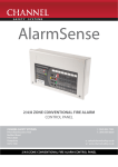
CHANNEL SAFETY SYSTEMS
t: 0845 884 7000 | w: www.channelsafety.co.uk
FoSmeter
Induction loop systems
from Channel Safety Systems
CHANNEL SAFETY SYSTEMS
Petersfield Business Park
Bedford Road
Petersfield
Hampshire
GU32 3QA
FOSMETER PRO (FPRO) INSTRUCTIONS
t: 0845 884 7000
f: 0845 884 6000
e: [email protected]
w: www.channelsafety.co.uk
FOSMETER PRO (FPRO) INSTRUCTIONS
| 1
CHANNEL SAFETY SYSTEMS
t: 0845 884 7000 | w: www.channelsafety.co.uk
400 mA MAGNETIC FIELD STRENGTH METER & LOOP LISTENER
Please read ALL of these instructions carefully before operating this equipment.
Headphone socket
Digital display
Power On &
Menu selection
left button
Menu selection
right button
ITEMS SUPPLIED
IMPORTANT NOTE
1 x Fosmeter Pro (FPRO)
1 x Protective pouch for the FPRO
1 x MP3 player (pre-loaded with test tones)
1 x HEAD1 Headphones (32 ohm)
1 x 9 V battery
1 x User Instruction (Doc. No. DCM0004006)
1 x FPRO Calibration Certificate (Doc. No. DCM0004007)
1 x AFILS Test Certificate (Doc. No. DCM0004008)
These instructions relate to the 400 mA
Fosmeter Pro (FPRO) when used to test an
audio frequency induction loop system
(AFILS) in accordance with BS EN 60118-4
(Magnetic field strength in audio frequency
induction loop systems).
FOSMETER PRO (FPRO) INSTRUCTIONS
| 2
CHANNEL SAFETY SYSTEMS
t: 0845 884 7000 | w: www.channelsafety.co.uk
INTRODUCTION TO TESTING INDUCTION LOOPS
PRODUCT DESCRIPTION
The FPRO aids the set up and maintenance of AFILS for compliance with BS EN 60118-4.
It has the following features:
•
A 400 mA fosmeter; combined magnetic field strength meter and loop listener.
•
Measures magnetic field strength, background noise, frequency response, metal compensation plus speech and music tracks.
•
A graphical LCD display; provides a user-friendly interface to simplify. Contrast control and battery life indication are also provided.
•
Two ‘soft’ buttons; dynamically change their functions to suit the menu options being accessed.
•
Auto power off feature; the fosmeter will warn the user after 10 minutes of inactivity, then give the user 30 seconds to shutdown the meter, or postpone
the event.
•
3.5 mm headphone jack socket; allows audible monitoring using HEAD1 (supplied).
•
An MP3 player (supplied) pre-loaded with test tones (1 kHz sine wave, frequency response and metal compensation), plus speech and music tracks to
assist with subjective testing.
•
Powered by a 9V PP3 battery (supplied).
INTRODUCTION TO TESTING INDUCTION LOOPS
Induction loop systems require careful testing and calibration prior to operation. The most efficient way of doing this is to use the FPRO. The current standard
BS EN 60118-4 recommends that the achievable magnetic field strength of an AFILS over a ‘covered area’ should be 400 mA RMS per metre. The most efficient
way of ensuring this requirement is met is to measure the magnetic field strength of a consistent output from an AFILS amplifier using the FPRO.
SPECIFICATION
Internal Battery
1 x 9 V PP3 battery (non-rechargeable)
Quiescent Current
25 mA
Battery Life
12 hours approx.
FPRO Test
Calibration
Measurement Scale
Frequency
Field Strength
400 mA/m (0 dB L)
as per BS EN 60118-4
<-22 to >+8 dB L
1 kHz detection
Frequency Response
400 mA/m (0 dB L)
as per BS EN 60118-4
<-22 to >+8 dB L
100 Hz / 1 kHz / 5 kHz detection
Background Noise
+/-1 dB L
<-42 to >-22 dB L
A-weighted detection
Metal Compensation
3rd octave band 1 kHz to 8 kHz
Headphone Socket
3.5 mm jack socket headphones (HEAD1)
Digital Display
LCD type (viewing area 50 mm diag.)
Weight
145 g approx. (plastic enclosure)
Overall Dimensions
117 mm x 79 mm x 18.5 mm
IP Rating
IP20
Note: The FPRO contains sensitive electronic equipment. It is designed for indoor use only and MUST NOT be subjected to conditions likely to
affect its performance.
FOSMETER PRO (FPRO) INSTRUCTIONS
| 3
CHANNEL SAFETY SYSTEMS
t: 0845 884 7000 | w: www.channelsafety.co.uk
METAL COMPENSATION MEASUREMENT
Metal Compensation Measurement
This test above and beyond the scope of BS EN 60118-4 and is designed to ensure
losses due to building structure and furnishings do not cause poor signal quality at
high audio frequencies. The FPRO measures frequencies 1 kHz through 8 kHz for use
with amplifiers capable of metal compensation functions.
(It is advised that this test is performed at user subjective level.)
1.
2.
3.
4.
Set up the test equipment and power up the FPRO.
Activate the MP3 player and transmit the metal compensation sine wave track
(Track 3).
From the main menu, select the ‘Metal Compensation’ menu option (see right).
Walk around the covered area and check good readings are achieved.
Acceptable results: Bar readings are levelled out
5.
6.
If good readings cannot be achieved, adjust the ‘Metal Compensation’ control
on the amplifier (if fitted) until a good range is displayed on the FPRO.
Carry out further checks at random within the covered area to confirm that the
metal compensation is acceptable.
Background Noise
Field Strength
Frequency Resp.
Metal Comp.
Loop Listener
Contrast
Shut Down
Down MENU Enter
Metal
Compensation
Will measure
frequencies
1kHz to 8kHz
Start
Exit
Metal Comp.
1
Hold
2
4
8
Exit
Metal Comp.
1
2
Sample
FOSMETER PRO (FPRO) INSTRUCTIONS
4
8
Exit
| 4
CHANNEL SAFETY SYSTEMS
t: 0845 884 7000 | w: www.channelsafety.co.uk
FREQUENCY RESPONSE MEASUREMENT
Frequency Response Measurement
This test is designed to ensure good speech intelligibility in the covered area. The
FPRO detects 100 Hz, 1 kHz and 5 kHz frequencies in accordance with BS EN 60118-4
and presents the results in the style of an easy-to-read bar graph. (BS EN 60118-4
recommends this test is done at levels of -10 dB L.)
1.
2.
3.
4.
Set up the test equipment and power up the FPRO.
Activate the MP3 player and transmit the frequency response sine wave track
(Track 2).
From the main menu, select the ‘Frequency Response’ menu option (see right).
Walk around the covered area and check good readings are achieved.
Background Noise
Field Strength
FrequencyR esp.
Metal Comp.
Loop Listener
Contrast
Shut Down
Down MENU Enter
Acceptable results: +/-3 dB L from a 1 kHz reference level
5.
6.
7.
If good readings cannot be achieved, adjust the ‘Metal Compensation’ control on
the amplifier (if fitted) until a good range is displayed on the FPRO.
Take readings and record the results on the AFILS Test Certificate.
Carry out further checks at random within the covered area to confirm that the
frequency response is acceptable.
Frequency
Response
Will measure
frequencies
100Hz,1 kHz
and 5kHz
Start
Exit
FrequencyR esp.
-12
-10
-13
100Hz1 kHz5 kHz
Hold
Exit
FrequencyR esp.
-12
-10
-13
100Hz1 kHz5 kHz
Sample
Exit
FOSMETER PRO (FPRO) INSTRUCTIONS
| 5
CHANNEL SAFETY SYSTEMS
t: 0845 884 7000 | w: www.channelsafety.co.uk
FPRO OPERATION
Pushbutton Controls
The FPRO’s two blue ‘soft’ buttons (shown above) change their functions dependent on the menu option being accessed. The bottom section of the digital
display denotes the buttons functions.
Which Button
Display Shows
Function
Down
Scrolls vertically through the menu options (see
Fig.1 & 2)
+
Left
Right
Adjusts the display’s contrast (see Fig.2)
Shutdown
Shutsdown the FPRO (see Fig.3 & 4)
Start
Starts a measurement test
Hold
Holds a measurement reading on the display
Sample
Restarts a measurement after a hold
Enter
Selects a menu option (see Fig.1 & 2)
Exit
Returns to main menu (see Fig.2)
Prevent
Postpones the FPRO’s auto shutdown (see Fig.3)
OK
Acknowledges a display message (see Fig.4)
Power Up & Switch On
Remove the battery cover on the back of the FPRO and insert the 9 V battery (supplied). Switch on the FPRO by pressing and holding its left button.
Shutting Down
From the main menu, select the ‘Shut Down’ menu option (see Fig. 1).
Contrast Control
The contrast of the LCD can be changed between a value of 35 and 95. When the contrast reaches 95 the display rolls back to 35. From the main menu, select
the ‘Contrast’ menu option (see Fig. 2).
Auto Shutdown & Battery Check
Auto shutdown occurs if none of the FPRO’s buttons are pressed for 10 minutes (see Fig.3). If ‘Prevent’ is selected, the display returns to the last used menu
option.
A battery level check runs in the background and warns the user if the level is low (see Fig.4). If OK is pressed the FPRO will run for 5 more minutes before the
user is warned again.
Fig.1
Please note: Always carry out testing using a good battery.
Background Noise
Field Strength
Frequency Resp.
Metal Comp.
Loop Listener
Contrast
Shut Down
Down MENU Enter
Fig.2
Background Noise
Field Strength
Frequency Resp.
Metal Comp.
Loop Listener
Contrast
Shut Down
Down MENU Enter
Contrast Level
Contrast = 50
+
Fig.3
Shutting Dow
No User Input
n
for 10 minutes
so the meter
is shutting down.
Shut
Down
FOSMETER PRO (FPRO) INSTRUCTIONS
Prevent
Exit
Fig.4
Battery Low
Measurements
will start to be
effected the
battery needs
replacing.
Shut
Down
OK
| 6
CHANNEL SAFETY SYSTEMS
t: 0845 884 7000 | w: www.channelsafety.co.uk
TESTING TO BS EN 60118-4
Test Equipment Set Up
1.
Connect an audio source, e.g. MP3 player, CD player, to a suitable line input/phono input at the AFILS amplifier using a suitable AL test lead (see diagram
below). Please note: AL leads are listed on page 1.
Lo
o
p
o
Lo
MP3 player
(pre-loaded with
test tones)
p
FPRO
AL
AFILS
Amplifier
(hold horizontally)
Lo
o
p
o
Lo
p
2.
Switch on the amplifier and adjust the input signal control and loop drive current in accordance with the
amplifier’s manual.
Background Noise & System Noise Measurements
This test is designed to ensure that background and system noise levels of the site / system do not affect the
intelligibility of the system in the covered area. Noise levels are measured by the FPRO and categorised as
Acceptable, Tolerable or Too High in accordance with BS EN 60118-4.
Background noise measurements should be taken before the AFILS is installed. Check if background noise levels in
the covered area are acceptable for an AFILS to be installed.
System noise measurements should be taken after the AFILS is installed. With the amplifier switched on, all inputs
muted, and other services
switched off, check if background noise levels in the covered area are acceptable.
Background Noise
Field Strength
Frequency Resp.
Metal Comp.
Loop Listener
Contrast
Shut Down
Down MENU Enter
Background Noise
Use to measure
background and
system noise
AW eightT est
Start
1.
2.
3.
Power up the FPRO.
From the main menu, select the ‘Background Noise’ menu option (see right).
Walk around the covered area and check good readings are achieved.
Acceptable results: > -42 dB L to < -32 dB L
Tolerable results: > -32 dB L to < -22 dB L
Too High: > -22 dB L (Bar will max out at -22 dB L)
4.
5.
Take readings and record the results on the AFILS Test Certificate.
Carry out further checks at random within the covered area to confirm that the background noise is
acceptable.
Exit
Background Noise
Acceptable
-41.8 dB L
Hold
Exit
Background Noise
Acceptable
-41.8 dB L
Sample
FOSMETER PRO (FPRO) INSTRUCTIONS
Exit
| 7
CHANNEL SAFETY SYSTEMS
t: 0845 884 7000 | w: www.channelsafety.co.uk
MAGNETIC FIELD STRENGTH MEASUREMENT
Magnetic Field Strength Measurement
This test is designed to ensure the loop signal provides sufficient volume without distortion in the
covered area. The FPRO detects a pulsed 1 kHz signal in accordance with BS EN 60118-4 and is calibrated
at 400 mA/m (i.e. 0 dB L).
1.
2.
3.
4.
5.
6.
7.
Set up the test equipment and power up the FPRO.
Activate the MP3 player and transmit the pulsed 1 KHz sine wave track (Track 1).
From the main menu, select the ‘Field Strength’ menu option (see right).
Walk around the covered area and check that 400 mA (0 dB L) is achieved, ideally in centre of the
loop.
If this cannot be achieved, adjust the ‘Gain’ or ‘Drive Control’ on the amplifier until a good reading is
displayed on the FPRO. Adjust the field strength (highest peak) to 400 mA/m = 0 dB L (+/-3 dB L).
Take readings and record the results on the AFILS Test Certificate.
Carry out further checks at random within the covered area to confirm that the field strength is
acceptable.
Background Noise
Field Strength
Frequency Resp.
Metal Comp.
Loop Listener
Contrast
Shut Down
Down MENU Enter
Field Strength
Use to measure
useful magnetic
field strength
Wide Band Test
Start
Exit
Field Strength
Good
+0.2 dB L
Hold
Exit
Field Strength
Good
+0.2 dB L
Sample
FOSMETER PRO (FPRO) INSTRUCTIONS
Exit
| 8
CHANNEL SAFETY SYSTEMS
t: 0845 884 7000 | w: www.channelsafety.co.uk
SUBJECTIVE / LOOP LISTENING TESTS
Subjective / Loop Listening Tests
This test is designed to ensure hearing aid users receive an undistorted and clear signal in the covered area
from the system’s actual inputs (microphones, music sources, etc.). The speech and music tracks, provided on
the MP3 player, can assist with subjective testing. The installation of an AFILS is performed with the purpose
of improving a service for the hearing impaired. Therefore, it is recommended that hearingaid users should be
present when the loop system is initially commissioned to confirm that measurements taken reflect
subjective tests. It is the opinion of these day-to-day users that should ultimately determine the output level of
the system.
1.
2.
3.
4.
1. Activate the system’s actual input(s). Power up the FPRO and connect the HEAD1 headphones to the
FPRO’s 3.5 mm jack socket. In the event of no real system inputs, use the speech track (Track 4)
and music track (Track 5) provided on the MP3 player.
From the main menu, select the ‘Loop Listener’ menu option (see right).
Walk around the covered area and check clear audio signals are achieved.
4. If possible, confirm the audio signals are acceptable to actual hearing-aid users.
Background Noise
Field Strength
Frequency Resp.
Metal Comp.
Loop Listener
Contrast
Shut Down
Down MENU Enter
Loop Listener
A Weight Test.
To ensure the
audio is clear
& undistorted.
Headphones Out
Exit
FOSMETER PRO (FPRO) INSTRUCTIONS
| 9
CHANNEL SAFETY SYSTEMS
Petersfield Business Park
Bedford Road
Petersfield
Hampshire
GU32 3QA
FOSMETER PRO (FPRO) INSTRUCTIONS
t: 0845 884 7000
f: 0845 884 6000
e: [email protected]
w: www.channelsafety.co.uk