1
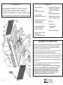
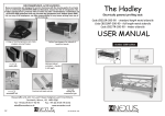
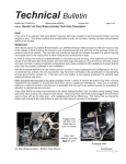
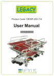
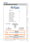
RECOMMENDED ACCESSORIES
Nexus accessories are designed to work in harmony with the moving parts of our beds and, in
conforming with EN1970-2000 bed Standard, reduce the risk of entrapment. Use of other
manufacturers’ products with our beds may take a bed/mattress combination out of EN1970-2000
guidelines and may increase the entrapment risk. Neither Nexus DMS Ltd, nor any of its employees,
can take responsibility for any issues arising from use of such products.
Hampton
Electrically powered profiling bed
Code CB12TR-200-90
USER MANUAL
A range of matched pressure care & nonpressure care mattresses
Safety foam bumpers for siderails &
head/foot boards
October 2009 edition
Matched siderail extenders
DMS Ltd
NE XUS
crashEX
safety mat
safety mat
lightEX
DMS Ltd
NE XUS
DMS Ltd
NE XUS
easyEX
Function-lock hand controls
reading lamp
reading and
examination light
movement aid
movement aid
Nexus DMS Ltd.,Unit 11, Lovett Road, Hampton Lovett Ind. Estate,
Droitwich, Worcs., UK. WR9 0QG
Tel: +44 (0) 19 05 77 46 95
Fax: +44 (0) 19 05 79 60 81
[email protected]
www.nexusdms.co.uk
12
NEXU
NEXU
DMS Ltd
DMS Ltd
R
Ref: NX.85.000 1009
R
SAFETY NOTICE
This manual contains important information regarding the safe & proper
assembly and use of the bed. It is important that any persons involved should
have read & understood its contents. Failure to do so could result in damage to
the bed and may invalidate the warranty. Be aware that elements of the bed are
heavy. Those involved should observe the safe lifting and handling techniques
recommended under Health & Safety Regulations.
PAY PARTICULAR ATTENTION TO THE FOLLOWING ADVICE.
(also refer to page 11 for guidance on Safe Working Loads)
ASSEMBLY & INSTALLATION.
* The bed should be assembled by suitably competent persons.
* Ensure that the local electricity mains voltage corresponds to that marked on the main controller label
before connecting to the supply.
* Ensure that cables from actuators are plugged into the main controller correctly.
* The fuse in the mains ‘safety connector’ plug should not exceed 5amps.
* The bed should be located on a level surface & not sited on loose floor coverings .
* The cable from the mains electricity supply must be routed clear of the lifting mechanism & castors to
avoid danger of shearing or crushing.
OPERATION.
*
*
*
*
The brake on each castor must be applied whilst the bed is in use (see also Page 8).
Do not allow children underneath the bed or to use the controls.
Do not position objects under the lifting mechanism of the bed.
Always ensure that limbs or body parts of both user and carer are not protrudung from the bed, are not
between the siderails or into the lifting mechanism when using the powered functions.
* Never exceed the maximum usage period of 2 mins continous use in any 18 mins. for any of the powered
functions. Should you do so the actuator may ‘close down’ for a period to recover.
* If, during operation, there are any unusual noises or smells then disconnect the bed from the mains
electricity power supply immediately. Ensure that no cables are trapped.
* When raising/lowering the bed be very aware of any fixtures such as window sills, shelf units & electrical
power sockets which may obstruct the raising of the bed. If necessary re-position the bed to avoid contact
and damage.
RE-SITING.
* If moving the bed to a different location always ensure that all bed functions are at their lowest position &
remember to remove the plug from the mains electricity power supply.
* Release all brakes before moving the bed, otherwise damage may occur.
* Never use the siderails to push or pull the bed. Always use the head and foot boards.
* With or without occupant, the bed should only be moved at slow speed & not pushed over a threshold strip
greater than 2cm in height.
* Once the bed is re-sited remember to re-apply the brakes.
MAINTENANCE & CARE.
* All wingscrews, grubscrews & mechanical fixings should be checked regularly for tightness.
* Use a damp cloth with normal household cleaners or warm soapy water to clean the bed. Do not use
cleaning agents containing ammonia, abrasives or strong solvents.
* Mechanical cleaning, scouring, pressure hoses or automated cleaning will damage the bed.
* All electrical actuators are fitted with maintenance-free self-lubricating bearings & no attempt should be
made to oil or grease these parts.
* A suitably qualified service engineer should check all electrical parts & cables and mechanical
functions for correct operation at least once every year.
* Any unauthorised modifications, adjustments or alterations will invalidate the product warranty.
* Repairs should only be carried out by a suitably qualified competent engineer.
* The Hampton bed is classed as a ‘double insulated appliance, although the supplied safety connector is
not. If the bed is used in commercial premises then customers should seek the advice of a qualified
electrician regarding PAT2 test recommendations.
Troubleshooting.
Fault
Remedy
No actuator functions
when hand control
Check connection to mains electricity supply & fuse; check
that the safety connector has not become disconnected;
operated
check connections of hand control and actuator plugs to
One actuator does not
Check connection between
work when button
actuator cable and controller.
main controller.
Is pressed.
TIP: If you have another Nexus bed of the same type (which you know is functioning correctly)
try the hand control off that bed - if this cures the problem then the original hand control is faulty.
Has the spiral cable been over-stretched or damaged in some way?
CB12TR Series Hampton bed - approx.component weights
Head/foot board + ‘T’ brackets
Mattress support - head end + 2 actuators
Mattress support - foot end+ no actuator
Scissor lift mechanism + chassis/castors
Main controller/mains cable/hand control
Siderail - each
Lifting pole+grab handle (where supplied)
No.
per bed
2
1
1
1
1
4
1
Standard
CB12TR-200-90
9.2 kg each
24.3 kg
17.3 kg
34.4 kg
2.0 kg
2.3 kg
5.5 kg
Those involved in the handling and assembly should follow Health & Safety guidelines and observe safe
lifting and handling techniques.
Technical Data
Operating voltage
~230V / 240V / 50Hz
Power reception
160 VA
Power duration
max. 2 mins in 18 mins (10%)
Appliance type B
Safety class II
Weight of bed
CB12TR-200-90 Standard Bed 104 kg (without mattress)
Safe Working Load (refer to P.9)
All versions 190kg (30 stones)
Product conforms to
EN 1970:08.2000
Product conforms to
EN 60601-1-1:1990
The Company reserves the right to make technical changes without notice.
SHOULD YOU HAVE ANY DOUBTS THEN PLEASE SEEK ADVICE!
2
NEXU
DMS Ltd
R
11
CONTENTS
PARTS LOCATOR
When telephoning for assistance or to order spare parts it is
essential we have the unique Serial Number from the bed.
This enables us to identify the correct items for the model of bed
and year of manufacture. A spare parts list is available on request.
35
23
4. Product identification.
Unpacking from the transit frame.
9
24
4
6
10
3
31
17
3. Contents
Features of the Hampton bed.
6. Assembly of mattress support to
the scissor / chassis unit.
Connecting the actuators.
9. Guidance on Safe Working Loads.
Guidance on mattress integrity.
10 Parts locator.
11. Troubleshooting.
Component weights.
Technical Data.
12. Recommended accessories.
7. Assembly of head / foot boards.
Fitting the siderails.
Fitting and use of the lifting pole.
8
27
2
30
29 22
5
7
28
14
8. Using Fowler position knee-break.
Raising & lowering the siderails.
Using the electrically powered
functions.
Applying & releasing the brakes.
5. Assembly of the mattress support.
Mounting the actuators.
Securing the mains cable.
1
These modular care beds have three electrically operated functions - back rest, leg rest & bed
height. These are powered by linear actuators. Fowler position knee-break adjustment is
standard fitment. Each of the actuators is sealed and uses maintenance-free permanent
lubrication. They are ingress protected to IP54 standard
The functions are operated using a 3-function hand control connected to the main controller
via a spiral cable. The hand control is ingress protected to IP54 standard.
All electrical functions are isolated from the mains supply & operate at 24v DC low voltage.
The mattress support is constructed from metal mesh which allows the mattress to breathe and
so prolongs its life.
21
20
FEATURES OF THE HAMPTON BED.
A 240V mains electrical ‘safety connector’ is supplied. This can reduce the likelihood of damage
or injury if the bed is moved before being unplugged from the mains power supply socket.
13
25
3
32
33
26
24
2. Important safety notice.
Nexus brand accessories are designed to work in harmony with the moving parts of
our beds and, in conforming with EN1970-2000 bed Standard, reduce the risk of
entrapment. Use of other manufacturers’ products with our beds may take a
bed/mattress combination out of EN1970-2000 guidelines and may increase the
entrapment risk. Neither Nexus DMS Ltd, nor any of its employees, can take
responsibility for any issues arising from use of such products.
11
18
19
16
15
The bed is supplied complete with timber ‘lift & lock’ siderails and beech finish head and foot
boards. Each castor features a simple to operate brake.
10
NEXU
3
DMS Ltd
R
PRODUCT IDENTIFICATION.
GUIDANCE ON SAFE WORKING LOADS
Each bed carries a label which identifies the
type of bed and its unique Serial Number.
The Safe Working Load MUST NEVER be taken as the maximum user weight.
Should you ever require advice or spare parts
then it is essential that you quote the Serial
Number - this enables us to match parts and
advice to your particular bed.
The identification label, similar to the one in the
picture, is located on either the scissor lift unit
adjacent to the mains power cable or approx.
half way along the side of the mattress support
unit.
In common with other manufacturers we quote a Safe Working Load for each of our beds.
When a bed is tested, a static load is evenly distributed over the whole surface of the bed.
Remember when a bed is in use that the load is rarely static or evenly distributed. Should a
visitor, for example, sit down heavily on one side of the bed then the shock load at that
point will be extreme, the load will be uneven & the total combined weight may exceed the
Safe Working Load. The SWL must take account not only of the weight of the user but also
the weight of the mattress, bed linen & other items loaded on to the bed eg. Air pump for
air-driven mattress.
You should also take account of any likely weight gain by the user in the future.
Typically, a mattress could weigh 20kg; an air-driven system could be as much as 30kg; a
couple of pillows 3kg; bed linen around 12kg - the total of such items, together with
anything else placed on the bed, PLUS the weight of the user must NEVER exceed
the Safe Working Load.
Bed Type
Serial No.
UNPACKING BED SECTIONS FROM THE TRANSIT FRAME.
Neither Nexus DMS Ltd, nor any of its employees, can accept responsibility for any issues arising from overloading
a bed. Should damage result from such actions then any necessary repairs will not be covered under warranty.
4
MATTRESS INTEGRITY.
Should a mattress cover be damaged then body or other fluids can pass through and
contaminate the inner core creating the potential for cross-infection.
It is therefore recommended that a frequent inspection of mattress covers is undertaken to
inspect for damage, such as holes or cuts. The inner core of the mattress should also be
inspected for signs of staining or contamination.
Should there be damage to a cover then it should be disposed of safely. Should there be
contamination to the inner foam core then it cannot be decontaminated and should therefore
be disposed of safely. Inner cells of an Optima air-float mattress system can be
decontaminated.
Foot end
Scissor unit
1. Carefully remove the shrink-wrapping & cardboard
packaging.
2. SUPPORT the HEAD & FOOT BOARDS, to avoid
. their
dropping & damaging, before carefully cutting
retaining straps. Lift both items clear of the bed.
3. The mattress support is in two halves - head end &
foot end, with the scissor lift mechanism located
between them.
Each half is located on the transit frame using 2
head / footboard mounting ‘T’ brackets. Identify the
foot end by its cups & blue disc knob screws part
way down the outer frame, loosen (but do not
remove) the 2 grubscrews at the base of the
mattress support (1 each side) and lift this section
clear of its two ‘T’ brackets on the transit frame.
Position safely.
4. Carefully cut straps securing the scissor unit to the
remaining (head end) half mattress support, lift
clear & position safely.
5. Remove the remaining half of the mattress
support (head end) by loosening (but not
removing) the 2 grubscrews at its base and lifting
clear of the ‘T’ brackets.
6. Remove the screws which secure the ‘T’ brackets
to the transit frame & fit 2 to each head / footboard
using the M8x25 button head cap screws supplied.
7. The timber transit frame can be retained for use in
the event the bed has to be stored or transported in
the future; it can be returned to Nexus or it can be
discarded.
Head end
It is recommended that his procedure be undertaken by two people.
PLEASE REFER TO THE SAFETY NOTICE ON PAGE 2
BEFORE ATTEMPTING TO UNPACK AND ASSEMBLE THE BED.
‘T’ bracket
Grubscrews
NEXU
DMS Ltd
R
9
USING THE FOWLER POSITION KNEE-BREAK
ASSEMBLY OF THE MATTRESS SUPPORT UNIT
The Fowler position knee-break is adjusted on ratchet mechanisms attached to the leg lift
section and can be adjusted both manually and electrically. There are 6 positions available so
that you can achieve the correct angle for a particular users knees.
MANUAL ADJUSTMENT: Raise the leg lift section electrically to a chosen height and then,
holding one of the mattress retaining handles, lift the foot section until it ‘clicks’ and remains at
the position you require. To lower - lift fully to its highest position (you will hear ‘clicks’) then
lower until the foot section rests on the mattress support unit.
ELECTRICAL ADJUSTMENT: Raise the leg lift section electrically until you achieve the knee
angle required. Lower electrically until you hear 1 ‘click’ then raise electrically to the height you
require. The chosen angle will be maintained. To lower - use the hand control and lower
electrically until flat.
1. Position the two halves of the mattress
support facing each other as shown. Note the
Clevis pin
position of the locating hole in the joining bar.
Locating holes
Unscrew the two grubscrews but do not
remove completely. (One each side)
2. Slide the sections together, ensuring both
sections fit fully together until the outer tubes ‘R’ clip
touch each other.
3. Position a clevis pin from the outside
Grubscrew
Slide together
through the outer tube and inner joining bar locking the 2 halves of the mattress support
assembly together. Attach the ‘R’ clip through
the small hole at the inner end of the clevis pin.
4. Tighten the 2 grubscrews on the underside of the mattress support very securely using an
Allen key. These should be rechecked for tightness periodically - refer to Page 2.
FOR EASE OF ASSEMBLY YOU SHOULD ALWAYS FIT THE 2 CLEVIS PINS AND ‘R’ CLIPS
BEFORE TIGHTENING THE 2 GRUBSCREWS.
RAISING & LOWERING THE SIDERAILS.
TO RAISE:
Hold the UPPER siderail at the head end & slide up the channel
until the locating pin engages with a ‘click’.
Both upper & lower rails are now locked in the upper position,
correctly spaced.
Repeat the procedure at the foot end.
For occupant safety always ‘lift & lock’ the siderails at the head end
first.
TO LOWER:
Hold the UPPER siderail & lift slightly until it stops. This action
‘unlocks’ the release button on the side of the footboard.
Press & hold the button & gently lower the siderails until they rest
on the stop at the bottom of the track.
Repeat the procedure at the foot end.
NEVER let go of the rails & allow them to drop.
For occupant safety always lower the rails at the foot end first.
release
button
Once the 2 halves of the mattress support unit have been assembled it is necessary to attach
the free ends of the back-lift and leg-lift actuators to their respective mounting points on the
opposite half of the mattress support assembly.
1. Locate the 2 ‘R’ clips and clevis pins - these are packed with User Manual & Grab Handle.
2. Carefully cut the cable-ties & swing each actuator into place, positioning the end of its arm
centrally in the mounting bracket legs - carefully aligning all 3 holes. NOTE that the leg-lift
actuator has the main controller attached to it. When fitting this actuator ensure that the
plug sockets face downwards to face the floor.
3. Fit each clevis pin with its retaining ‘R’ clip securely.
USING THE POWERED FUNCTIONS.
BACK-LIFT ACTUATOR
BEFORE USING ANY POWERED FUNCTION PLEASE
READ THE SAFETY NOTICE ON PAGE 3.
Hampton beds are supplied with a hand control, similar to the
one pictured. This controls the raising of the back rest, leg rest
& bed height.
The 3 buttons to the left control the ‘raise’ functions & the 3
buttons to the right the ‘lower’ functions.
Each button carries a pictogram to denote its function.
A clip on its rear allows it to be positioned conveniently on a
siderail.
As an example: pressing the uppermost button on the left of
the handset will raise the backrest. Whilst the button is being
pressed the backrest will continue to lift. Release the button
and the backrest will stop in the position it is in.
8
LEG-LIFT ACTUATOR
NOTE: The Main Controller is attached to this actuator.
When positioning, ensure that the sockets face downwards.
release
SECURING THE MAINS CABLE TO THE MATTRESS SUPPORT UNIT
It is important that the mains cable is securely attached to the mattress support unit. Unscrew
the silver nut from the grey plastic gland on the cable. Position the gland through the
mounting bracket on the underside of the mattress support unit (head end), re-fit the nut and
tighten - taking care not to over-tighten, otherwise the plastic screw threads may be damaged.
APPLYING & RELEASING THE BRAKES.
For safety reasons the brake on each castor must be
applied when the bed is in use.
They must be released before moving the bed.
MOUNTING THE ACTUATORS TO THE MATTRESS SUPPORT UNIT
apply
5
ASSEMBLY OF MATTRESS SUPPORT TO SCISSOR LIFT CHASSIS
ASSEMBLY OF HEAD / FOOT BOARDS
1. Position the assembled mattress support unit on its
side with the lifting pole sockets to your left & the
electrical parts facing you. This places the ‘head’
end to your left. Pull out the back and leg sections
by hand to support the unit.
2. On the underside of the mattress support (facing
you) note the positions of (a) the steel ‘slide’ at
each side of the head end & (b) the ‘cups’ with
disc knobs at each side of the foot end - loosen
these two disc knobs but do not remove.
3. Identify the head end of the scissor lift chassis
(the oblong carrier blocks are at the head end, the
tapered blocks at the foot end).
4. Position the scissor lift chassis on its side, close to
the mattress support unit, with the castors facing
you & the oblong carrier blocks to the left. (Head
end to the left).
5. Identify the four white plastic carrier blocks - the
two at the head end (c) are grooved - swivel these
such that the grooved side faces towards you.
Those at the foot end (d) are tapered - swivel both
such that the tapered end faces you.
6. Position the head end carrier blocks into the two
steel slides on the mattress support unit (grooves
towards you).
7. Position the foot end tapered carrier blocks into
the two steel cups (tapered end facing you).
Securely tighten the two disc knobs by hand.
The head & foot boards are identical & can be fitted to either end of the bed.
1. At each end of the mattress support tubular section, on the underside, are two grubscrews
- one at each side. (these were loosened when removing sections from the transit frame).
2. The head / foot boards each have two metal ‘T’ brackets.
3. Slide the two ‘T’ brackets fully into the open end of the tubular section.
4. Securely tighten the grubscrews on the underside of the mattress support.
e
b
d
e
c
FITTING THE SIDERAILS.
a
KEY
a - steel slide
b - steel cup
c - grooved
carrier block
d - tapered
carrier block
e - disc knob
e
b
d
CONNECTING THE ACTUATORS TO THE MAIN CONTROLLER.
There are 3 actuators on scissor-lift models. Each is connected to the Main Controller by a spiral
B
cable and multi-pin plug. The plugs are ‘keyed’ & will only insert if correctly
aligned in the socket.
There is a locking strap over the sockets - this should be released, using the tip of a small
screwdriver, before attempting to fit the plugs & snapped back afterwards to ‘lock’ the plugs in
place.
Assemble each of the plugs & then fasten the spiral cables into their retaining loops on the
underside of the bed so that they do not trail on the floor.
Take great care to ensure that cables are clear of actuators & that there is sufficient slack to allow
for the movement of bed parts.
The actuators are connected as follows:
Socket 1: Back-lift: Socket 2: Leg-lift: Socket 3: Height adjustment Socket 4: b l a n k
Hand control plug
Release lug
1. The four black ‘finger’ assemblies, on which the siderails locate, are
packed separately. One of these assemblies fits into the aluminium
track at each side of each head/foot board.
2. At the bottom of each aluminium track is an end-stop to retain the
finger assembly. This is fitted to the track during production.
Each should be un-screwed partially, until the screw clears its
locating hole in the track, and the complete assembly removed.
3. At one end of the bed only slide a finger assembly upwards into
each of the 2 tracks, ensuring that the pointed end of the slider faces
UPWARDS. Slide up until you hear the click as it locks in its upper
position. (you may need to press the button on the side of the
head/foot board to release the lock.) Refit the end-stops, ensuring that
the screws locate in the drilled holes in the track and that the washers
are located on the outside of the track (see picture). Tighten, but do not
over-tighten the screws.
4. Slide a siderail onto each pair of fingers (4 in total).
5. At the other end of the bed remove the end-stops from the
aluminium tracks (see 2 above). Take the 3rd & 4th finger assemblies
(pointed end upwards) & slide into the other ends of the siderails.
At each side of the bed place the finger+siderail assembly in the
bottom of the open track and slide up until it locks. Refit the end-stops,
again ensuring that the screws locate in the drilled holes in the track
and that the washers are located on the outside of the track (see
picture). Tighten, but do not over-tighten the screws.
FITTING THE LIFTING POLE (when ordered)
1. There is a socket for the lifting pole on each side of the bed at the
head end.
2. Insert the lifting pole into either the left or right hand socket.
3. Rotate the pole until the pin on the pole locates in the corresponding
groove in the socket - this keeps the pole correctly and securely
positioned for use.
4. Hang the grab handle over the end of the pole between the two
vertical pins & adjust the strap to the required length.
5. The pole can be lifted slightly to free the pin & swung out of the way
when not in use. It must NOT bear any weight when in this
position.
Locking strap
6
7