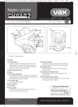
1
Troubleshooting.
Fault
Action
No actuator functions
when the hand control
Check connection to mains electricity supply & fuse; check
that the safety connector has not become disconnected;
buttons are pressed
check connections of hand control and actuator plugs to
main controller.
One actuator does not
Check the coiled cables connection between
work when the button
the actuators and the hand controls.
Electrically powered profiling & standing bed
for use in critical / acute care
Code CB3ST-200-90
with one-piece leg-lift & metal siderails
Code CB3STKB-200-90
with knee-break adjustment & metal siderails
is pressed.
An actuator starts but switches Check the coiled cable & the connection between
itself off before the end
Standing Bed
the actuator and the hand control.
position is reached.
An actuator switches itself off
The maximum operating time has been exceeded. Wait for
& does not respond when the
20 minutes to allow the thermal fuse to cool, then try again.
button is pressed.
USER MANUAL
January 2012 edition
Technical Data.
Operating voltage
~230V / 240V / 50Hz
Rated power output
960 VA
Power duration
max. 6 mins in 60 mins (10%)
Appliance type B
according to IEC 601-1
Safety class II
IP protection
Hand Control & Actuators IP55; Limit Switch IP65
Noise level
63 dB(A)
Safe Working Load (refer to P.9)
260kg (41 stones)
Weight of bed
180 kg (without mattress)
Dimensions of lying surface
200cm x 90cm
Height adjustment
40.5cm to 80cm (without mattress)
Backlift section adjustment
0° to 62°
Leglift section adjustment
0° to 43°
Product conforms to
EN 1970:08.2000
Product conforms to
EN 60601-1-1:1990
Product conforms to
EU directive for Medical Devices 93/42/EEC, Annex 1
The Company reserves the right to make technical changes without notice.
12
R
Nexus DMS Ltd.,Unit 11, Lovett Road, Hampton Lovett Ind. Estate,
Droitwich, Worcs., UK. WR9 0QG
Tel: +44 (0) 19 05 77 46 95
Fax: +44 (0) 19 05 79 60 81
[email protected]
www.nexusdms.co.uk
NEXU
DMS Ltd
01/12
R
SAFETY NOTICE
This manual contains important information regarding the safe & proper
assembly and use of the bed. It is important that any persons involved should
have read & understood its contents. Failure to do so could result in damage
to the bed and may invalidate the warranty. Be aware that elements of the bed
are heavy. Those involved should observe the safe lifting and handling
techniques recommended under Health & Safety Regulations.
PAY PARTICULAR ATTENTION TO THE FOLLOWING ADVICE.
(also refer to page 9 for guidance on Safe Working Loads)
ASSEMBLY & INSTALLATION.
* The bed should be assembled by suitably competent persons.
* Ensure that the local electricity mains voltage corresponds to that marked on the main
controller label before connecting to the supply.
* Ensure that cables from actuators are plugged into the main controller correctly.
* The fuse in the mains ‘safety connector’ plug should not exceed 13amps.
* The bed should be located on a level surface & not sited on loose floor coverings .
* The cable from the mains electricity supply must be routed clear of the lifting mechanism &
castors to avoid danger of shearing or crushing.
OPERATION.
* The brake on each castor must be applied whilst the bed is in use (see also Page 8).
* Do not allow children underneath the bed or to use the controls.
* Do not position objects under the lifting mechanism of the bed.
* Always ensure that limbs or body parts of both user and carer are not protrudung from the
bed, are not between the siderails or into the lifting mechanism when using the powered
functions.
* Never exceed the maximum usage period of 6 mins continous use in any hour for any of
the powered functions, otherwise a thermal fuse may be triggered - in which case a ‘cooling
down’ period of 20 mins. must be observed.
* If, during operation, there are any unusual noises or smells then disconnect the bed from the
mains electricity power supply immediately. Ensure that no cables are trapped.
* When raising/lowering the bed be very aware of any fixtures such as window sills, shelf units
& electrical power sockets which may obstruct the raising of the bed. If necessary re-position
the bed to avoid contact and damage.
RE-SITING.
* If moving the bed to a different location always ensure that all bed functions are at their lowest
position & remember to remove the plug from the mains electricity power supply.
* Release all brakes before moving the bed, otherwise damage may occur.
* Never use the siderails to push or pull the bed. Always use the head and foot boards.
* With or without occupant, the bed should only be moved at slow speed & not pushed over a
threshold strip greater than 2cm in height.
* Once the bed is re-sited remember to re-apply the brakes.
MAINTENANCE & CARE.
* All wingscrews, grubscrews & mechanical fixings should be checked regularly for tightness.
* Use a damp cloth with normal household cleaners or warm soapy water to clean the bed. Do
not use cleaning agents containing ammonia, abrasives or strong solvents.
* Mechanical cleaning, scouring, pressure hoses or automated cleaning will damage the bed.
* All electrical actuators are fitted with maintenance-free self-lubricating bearings & no attempt
should be made to oil or grease these parts.
* A suitably qualified service engineer should check all electrical parts & cables and mechanical
functions for correct operation at least once every year.
* Any unauthorised modifications, adjustments or alterations will invalidate the product warranty.
* Repairs should only be carried out by a suitably qualified competent engineer.
* The Standing Bed is classed as a ‘double insulated appliance, although the supplied safety connector is
not. If the bed is used in commercial premises then customers should seek the advice of a qualified
electrician regarding PAT2 test recommendations.
SHOULD YOU HAVE ANY DOUBTS THEN PLEASE SEEK ADVICE.
2
LOWERING THE BED SURFACE IN AN EMERGENCY.
(What to do in the event of a power failure should the
bed be in a standing/upright position)
Spring clip
The Standing Bed incorporates a manual
function to enable the mattress platform to be
lowered from the upright to horizontal position
by hand, in the event of a power failure or
emergency.
A locking lever is mounted on the right hand
side of the lifting assembly (Fig 15).
Unscrew
Fig 15
Push
down
To manually return the bed from standing to
horizontal proceed as follows:
Remove the spring ‘R’ clip from the end of the
threaded rod (Fig 15).
Pull the locking lever whilst, at the same time,
fully unscrewing the threaded rod (Fig 15).
Apply downward pressure on the motor so
that it swings downwards (Fig 16).
Fig 16
Pull downwards on the mattress platform to
lower to the horizontal position. Two
pneumatic rams enable the bed, including
patient, to be lowered with little effort.
CLEANING & MAINTENANCE
Clean the tubular elements of the bed surface and the timber components using a
damp cloth with a household cleaning agent which does not contain scouring agents
or ammonium chloride. Solvents will damage the coating on the bed surface.
Mechanical cleaning or jet-washing should not be employed.
All rotating joints of moving parts, including the bearing lugs on the adjustment
mechanism, have maintenance-free friction bearings and must not be oiled or
lubricated.
REGULAR CHECKS:
All screws firmly secured.
Rotating joints move freely.
Inspect mains cable for crushing or shearing.
Inspect mains cable strain relief.
All electrically operated functions are operating correctly.
Check correct function of the brake on each castor.
Check security and free movement of siderails.
11
GENERAL OPERATING INSTRUCTIONS
* After installation and before use, check that all electrical and mechanical connections are
fastened securely in place.
* Ensure that the actuators(motors) are functioning correctly.
* Ensure that no objects, such as waste bins, tables, chairs etc are positioned within the range of
movement of the bed functions.
* In order to prevent injury during operation of the bed you should ensure that no parts of the
patients body protrude beyond the bed surface.
* Before moving the bed you must always disconnect the mains plug from the wall socket.
* When a patient is on the bed then the bed can only be pushed over bumps (eg door threshold)
with a maximum height of 2cm only.
* The maximum ‘power on’ time must be observed. Do not perform long & unnecessary electrical
adjustments. Should a thermal fuse be triggered, once the maximum 6 minutes per hour
operating time has been exceeded, then you must wait 20 minutes for it to cool down before
attempting to use any of the electrical functions of the bed.
* When the bed has been positioned you must always apply the brake on each castor.
* It may be possible for bed functions to be operated unintentionally eg. A child playing with the
hand control; a heavy object falling on the hand control etc. Should the carer consider that a risk
of this nature exists then the bed must be left unpowered - by either removing the mains plug
from the wall socket or by switching the key safety switch to the ‘off’ position and removing the
key. (See opposite page)
GUIDANCE ON SAFE WORKING LOADS
The Safe Working Load MUST NEVER be taken as the maximum user weight.
In common with other manufacturers we quote a Safe Working Load for each of our beds.
When a bed is tested, a static load is evenly distributed over the whole surface of the bed.
Remember when a bed is in use that the load is rarely static or evenly distributed. Should a
visitor, for example, sit down heavily on one side of the bed then the shock load at that
point will be extreme, the load will be uneven & the total combined weight may exceed the
Safe Working Load. The SWL must take account not only of the weight of the user but also
the weight of the mattress, bed linen & other items loaded on to the bed eg. Air pump for
air-driven mattress.
You should also take account of any likely weight gain by the user in the future.
Typically, a mattress could weigh 20kg; an air-driven system could be as much as 30kg; a
couple of pillows 3kg; bed linen around 12kg - the total of such items, together with
anything else placed on the bed, PLUS the weight of the user must NEVER exceed
the Safe Working Load.
Neither Nexus DMS Ltd, nor any of its employees, can accept responsibility for any issues arising from overloading
a bed. Should damage result from such actions then any necessary repairs will not be covered under warranty.
MATTRESS INTEGRITY.
Should a mattress cover be damaged then body or other fluids can pass through and
contaminate the inner core creating the potential for cross-infection.
It is therefore recommended that a frequent inspection of mattress covers is undertaken to
inspect for damage, such as holes or cuts. The inner core of the mattress should also be
inspected for signs of staining or contamination.
Should there be damage to a cover then it should be disposed of safely. Should there be
contamination to the inner foam core then it cannot be decontaminated and should therefore
be disposed of safely. The inner cells of an Optima air-float mattress system can be
decontaminated.
10
CONTENTS
2. Important safety notice.
8. Using the electrically powered
functions.
Using Fowler position knee-break.
Using the safety key-switch.
3. Contents.
Features of the Standing bed.
9. General operating instructions.
Guidance on Safe Working Loads.
Guidance on mattress integrity.
4. Product identification.
Assembly & Installation.
5. Assembling the timber parts.
10. Emergency lowering of the bed.
Cleaning & Maintenance.
6. Fitting the siderails.
Raising & lowering the siderails.
7. Assembling the belt straps & clips.
Use of the braked castors.
11. Troubleshooting.
Technical Data.
FEATURES OF THE STANDING BED.
The Standing Bed has been designed for the treatment of patients who need to become
accustomed to a standing position and to improve kidney function & circulation in bed-ridden
patients.
The beds have a lying surface of 200cm x 90cm and are equipped with 4 electrically operated
functions: height adjustment; standing function; backrest adjustment & legrest adjustment with,
or without, Fowler position knee-break adjustment.
The height adjustment & standing functions block each other out such that, for safety reasons,
the standing function cannot be operated until the lying surface is in its highest position.
Functions are operated by maintenance-free electromechanical linear actuators which are
ingress protection rated to IP55. They are controlled by 2 hand control units, also rated to IP55.
All electrical functions are isolated from the mains supply & operate at 24v DC low voltage.
A 240V mains electrical ‘safety connector’ is supplied. This can reduce the likelihood of damage
or injury if the bed is moved before being unplugged from the mains power supply socket.
The mattress support is constructed from timber slats which allows the mattress to breathe and
so prolongs its life.
The bed is supplied with standard or full length metal ‘lift & lock’ siderails.
Each castor features a simple to operate brake.
Nexus brand accessories are designed to work in harmony with the moving parts of
our beds and, in conforming with EN1970-2000 bed Standard, reduce the risk of
entrapment. Use of other manufacturers’ products with our beds may take a
bed/mattress combination out of EN1970-2000 guidelines and may increase the
entrapment risk. Neither Nexus DMS Ltd, nor any of its employees, can take
responsibility for any issues arising from use of such products.
NEXU
DMS Ltd
R
3
USING THE ELECTRICALLY POWERED FUNCTIONS - contd.
PRODUCT IDENTIFICATION.
Each bed carries a CE label similar to the
one pictured here. This identifies the type
of bed, its product code and its unique
Serial Number. DISPLAY OF THIS CE
LABEL IS A LEGAL REQUIREMENT.
IT MUST NOT BE REMOVED.
Should you ever require advice or spare
parts then it is essential that you quote
the Serial Number - this enables us to
match parts and advice to your particular
bed.
STANDING FUNCTION
The bottom row of buttons on the roving Hand Control operate the standing function of
the bed. Pressing the ‘up’ button will raise the mattress support to a standing position.
Simply release the button when the required angle of ’stand’ has been reached. Note
that before the mattress platform begins to raise then the bed height will be raised
automatically to ensure there is sufficient floor clearance. Once the mattress platform
is in its fully ‘stood’ position then bed height ‘down’ button may be pressed in order to
lower the platform closer to the floor - it will stop automatically before making contact
with the floor.
Model
Product
Code
Serial No.
The following procedure is better completed by two people.
PLEASE REFER TO THE SAFETY NOTICE ON PAGE 2
BEFORE ATTEMPTING TO UNPACK AND ASSEMBLE THE BED.
Operation using the fixed Control Panel is the same as the roving Hand Control
except that you must press the Standing function button whilst at the same time
pressing the ‘up’ or ‘down’ arrow key.
NOTE: If the backrest and/or legrest are in a raised position before operating the
standing function then, for safety reasons, they will both be lowered to their
respective flat positions automatically before the standing function will operate.
ASSEMBLY & INSTALLATION
BACKREST and LEGREST (see Page 7 for adjustment of knee-break angle)
The bed must be assembled and installed only by authorised persons.
By pressing the up/down button on the roving Hand Control or the function button
together with with up/down button on the Fixed Control Panel then the back or leg
rests can be raised. Simply release the button when the required angle has been
achieved. To lower, simply press the down button (or function + down button on the
Fixed Control Panel).
NOTE: If the backrest and/or legrest are raised when pressing the Standing button
then they will be automatically levelled before the bed stands.
NOTE: Before raising the backrest or legrest ensure that the body retaining straps are
released.
The fuse in the mains plug must not exceed 13A. Before connecting the bed to the
mains electrical supply ensure that the voltage and frequency of the mains supply
comply with the specifications on the CE / Product Identification label (see above).
The bed must be positioned on a level surface. If it is to be moved around regularly
then suitable floor covering should be provided. Carpets, rugs and other loose floor
coverings can be damaged or may impede movement of the bed. ‘Bunched-up’
carpets and rugs create a trip hazard.
MATTRESS SUPPORT HEIGHT
Supplied with the bed is a Safety Connector with a 2-pin socket leading to a 3-pin UK
mains plug. Securely connect the 2-pin plug at the end of the bed mains power cable
into the 2-pin socket of the Safety Connector and then securely connect the 3-pin
mains plug into a wall socket. Lay the mains power cable along the floor, ensuring
that the castors of the bed do not rest on the cable (particularly when moving the
bed). The cable must not be routed through the mechanism underneath the bed to
avoid the risk of crushing or shearing the cable.
By pressing the up/down button on the roving Hand Control or the function button
together with with up/down button on the Fixed Control Panel then the height of the
mattress support can be adjusted. Simply release the button when the required height
has been achieved. To lower, simply press the down button (or function + down button
on the Fixed Control Panel).
NOTE: When moving or transporting the bed........
By pressing the up/down button on the roving Hand Control then the backrest and
legrest will be raised together to form the ‘chair’ position. Simply release the button
when the required angle has been achieved. To lower, simply press the down button.
(This feature is not available on the Fixed Control Panel).
NOTE: The chair position is achievable with the mattress platform ‘stood’ at an angle
of up to 120 maximum. For safety reasons the chair function will not operate
when the mattress platform is above 120.
NOTE: Remember to release the body retaining straps before raising backrest and/or
Legrest.
9
You should do so ONLY with ALL lifting parts of the bed at their LOWEST positions.
You must NOT run over or pinch the mains power cable or the coiled hand control
cables.
NEXU
DMS Ltd
4
R
CHAIR POSITION
SAFETY SWITCH
Fig 13
The electrically operated functions can be
switched on & off using the key in the electrical
safety switch.
In the ‘off’ position (Fig 14) the key can be
removed in order to prevent any unintentional
operation of bed functions.
The bed is ready for use when the key is inserted
and turned to the ‘on’ position. (Fig 13)
IT IS RECOMMENDED THAT THE KEY BE
REMOVED BEFORE LEAVING THE ROOM.
Large washer
Fig 1
There are 2 methods of controlling the elctrically-operated functions of the bed:
Using this fixed Control Panel, you are
able to control bed functions by pressing
and holding the required function button
on the top row, followed by the up/down
arrow button as appropriate. The following
functions are controllable in this way:
Backrest angle
Legrest angle
Mattress support height
Bed standing function
8
Using this same Control Panel you are
able to LOCK any / all of the above
functions in order to avoid accidental
operation. Simply press and hold the ‘key’
symbol button together with the function
button you wish to lock. A light will show to
indicate that the function is deactivated. To
UNLOCK the function simply repeat this
procedure.
2. A roving Hand Control unit.
The roving Hand
Control plugs into the
main control box via a
spiral-wound cable.
You should avoid
over-stretching the
cable to avoid
damage to the fine
inner wires.
Using the roving
Hand Control, you
are able to control
operation of the
following bed
functions:
Mattress support
height
Backrest angle
Standing function
For beds with a table tube
bracket TWO washers
must always bused in
order to allow sufficient
space between the metal
frame & the side panel.
Fig 14
USING THE ELECTRICALLY POWERED FUNCTIONS
1. A Control Panel which is
securely fixed to the bed frame.
Side panel
Fig 2
Washer & M6 nut
Screw the timber side panels onto the metal
frame using the screws, washers & M6 nuts
provided (Fig 1 & 2).
After assembling the side panels, attach the
head and foot boards by inserting the
countersunk screws through the head or foot
board and into the side panels (Fig 3).
Fig 3
Then secure the head and foot boards on the
inside of the side panels using 4 x M6 nuts at
each end (2 each side) (Fig 4).
Finally, cover the screw holes with the brown
plastic caps provided (fig 5).
Legrest angle
Chair function
The buttons on the left-hand side control
the upward movement of a particular
function and the buttons on the right
control the downward movement.
Simply press and hold the appropriate
button until the desired height/angle is
achieved, then release.
A function which has been ‘locked’ on
the fixed Control Panel cannot be
operated by the Hand Control, until it
has been unlocked.
Fig 4
Once the head and foot boards are mounted
then the removable footplate can be inserted
into the appropriate tube and secured using the
set-screws and Allen Key provided. (Fig 5).
NOTE: The footplate should only be installed if
the patient has to stand, otherwise it may impair
vision and possibly hinder care of the patient in
a lying position.
Plastic cap
Set screw
Fig 5
wingscrew
5
FITTING THE METAL SIDERAILS.
Fig 6
Slide
bracket
Fig 7
Springloaded
pin
ASSEMBLING BELT STRAPS & CLIPS..
Push the belt strap under the belt clip
and through slot 1 (Fig 8) - as shown
In Fig 9.
1. Two slide brackets are pre-assembled
each side of the mattress support unit.
(Fig 6)
2. Rotate the brackets so that the springloaded release/lock pins are on the left
hand side of the slide ( as you look at
the bed).
3. Now slide one end of a siderail into the
raised slide bracket until it hits the pin.
4. Pull out the spring-loaded pin, lower the
siderail & release the pin. Continue to
lower the siderail until the pin locates in
the hole in the siderail. (Fig 7)
5. Repeat the process at the other end &
for the second siderail.
Press the belt clip together - as shown
by the arrows in Fig 9............
Fig 9
Fig 8
Belt clip
Belt strap
Push together
at these points
Slot 1
.......this will create the opening at slot 2
(Fig 10) through which to pass the belt
strap - as seen in Fig 11.
The strap length can then be adjusted
to suit an individual user by pulling the
end of the strap.
Fig 10
Fig 11
Slot 2
RAISING & LOWERING METAL SIDERAILS
TO RAISE: From its lowest position hold the upper tubular section & slide upwards
through the brackets until the spring-loaded release/lock pins locate in the holes in the
vertical sections of the rail. The siderail is now locked at each end in the upper position. If
lifting each end separately then, for safety, it is recommended that you lift & lock the head
end first.
TO LOWER: Support the foot end of the rail, pull out the silver locating pin & lower the rail
gently until it stops. Repeat at the head end. For occupant safety always lower the foot
end first.
TO REMOVE COMPLETELY: From its upper, locked position, support the rail, pull out
the pins & lift further until the rail clears the brackets. When re-fitting, the spring-loaded
pins must be on the left hand side of the brackets when looking at the bed.
NOTE: always ensure that the belt strap is fed into the belt clip from the right hand side,
as shown in the pictures.
The belt clips, shown above, fit into the buckles attached to each side of the
padded support straps. Each buckle is released by depressing the red button.
IMPORTANT - it is very important that the padded support straps with attached buckles
are always used the correct way round ie. with the red release button uppermost. If
used upside down then it can result in damage to the buckles. You should also ensure
that no straps or buckles become trapped in any of the moving parts of the bed as their
plastic casings can be easily damaged.
USING THE FOWLER POSITION KNEE-BREAK
APPLYING & RELEASING THE BRAKES.
release
For safety reasons the brake on each castor
must be applied when the bed is in use.
They must be released before moving the bed,
otherwise damage may result.
Fig 12
6
apply
The Fowler position knee-break is adjusted on ratchet mechanisms attached to the
leg lift section and can be adjusted both manually and electrically. There are 6
positions available so that you can achieve the correct angle for the knees of a
particular user.
MANUAL ADJUSTMENT: Raise the leg section electrically to a chosen height and
then, holding one of the mattress retaining handles, lift the foot section until it ‘clicks’
and remains at the position you require. To lower - lift fully to its highest position (you
will hear ‘clicks’) then lower until the foot section rests on the mattress support unit.
ELECTRICAL ADJUSTMENT: Raise the leg section electrically until you achieve the
knee angle required. Lower electrically until you hear 1 ‘click’ then raise electrically to
the height you require. The chosen angle will be maintained.
To lower - use the hand control and lower electrically until flat.
7