1
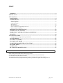
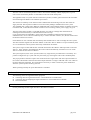
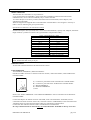
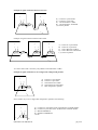
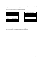
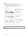
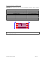
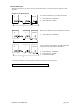
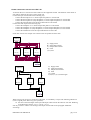
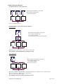
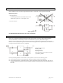
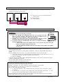
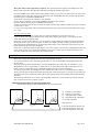
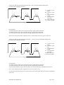
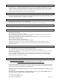
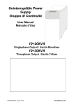
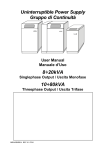
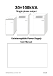
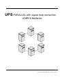
UPS PARALLEL with signal loop connection
USER’S MANUAL
0MNA001ANE-GB.REV00 / ITDA / 23/01/04
INDEX
WARNING ..........................................................................................................................................3
INTRODUCTION .................................................................................................................................................. 4
INSTALLATION.................................................................................................................................................... 4
POSITIONING ...................................................................................................................................4
CONNECTIONS ................................................................................................................................5
Signal connection ............................................................................................................................................ 5
Firmware update.............................................................................................................................................. 5
Loop Connection ............................................................................................................................................. 5
Hot Insertion.................................................................................................................................................... 8
Hot Disconnection ......................................................................................................................................... 10
Power connection “input/output UPS” AC.................................................................................................... 11
Power connection “Battery” .......................................................................................................................... 12
DIFFERENTIAL PROTECTION ..................................................................................................13
ADDITIONAL SECTIONING........................................................................................................13
EMERGENCY POWER OFF (EPO) CONNECTION ................................................................14
START UP ........................................................................................................................................14
FUNCTIONING MODES.................................................................................................................................... 15
Example ofFunctioning of the Loop Connection .......................................................................................... 15
ON LINE MODE ..............................................................................................................................17
STAND-BY ON MODE ...................................................................................................................17
STAND-BY OFF MODE .................................................................................................................17
STABILIZER MODE WITHOUT BATTERY .............................................................................17
BATTERY MODE ...........................................................................................................................17
OVERLOAD .....................................................................................................................................17
BY-PASS FOR MAINTENANCE...................................................................................................17
WARNING
Read carefully this manual before making any operation.
All the installation operations must be carried out exclusively from personal trained.
Use this manual with the UPS user manual.
The instructions in this manual are applicable only to modified UPS for parallel operation.
A standard machine not predisposed for the parallel is possible to be update across the parallel kit.
0MNA001ANE-GB.REV00
pag. 3/18
INTRODUCTION
The UPS can be connected in parallel in order to increase the reliability and the output power. Up to 8
units can be connected in parallel. It’s advisable connect unit of the same power.
The applicable load, in a system with more machines in parallel, could be greater than the load sustainable
from each single unit thanks of an automatic power share.
The increase in reliability can be achieved with condition that disconnecting a unit, the other UPS can
supply the load. This important condition can be achieved by adding a redundant unit to the system.
The redundant unit is achieved by adding an additional UPS to the minimum number of elements necessary
to feed the load, so that after the automatic exclusion of a not-working unit the power supply can go on.
The UPS connected in parallel is controlled through a card, which exchange data. Information are
exchange between the UPS by a cable that them connects in Loop.
Loop connection has the redundancy on the signal cable (redundant communication link between
individuals units). So it is the most reliability way to connect the UPS. It allows, also, the hot insertion and
the hot disconnection of an UPS.
Each UPS has its own controller that continuously intercommunicate in order to manage the entire system.
The cable transmits signals from the UPS "Master" to the other "Slaves" thanks to an opto-insulated system
so as to maintain the control systems electrically isolated from each other.
The system’s logic assumes that the first activated unit becomes the "Master" and keeps under control the
"Slaves". If the "Master" unit malfunction the control will be automatically switched over to one of the
"Slaves" which becomes the new "Master".
The system requires (in the “base” operation) that every single unit be provided with its own battery. It is
possible configure the ups system with only one battery (by inserting the code on the command panel).
The proper parallel connection requires the connection from a single mains node to the input terminals of
the various UPS and the connection from their output terminals to a single load feed node with cables of
the same thickness and length. This requirement is necessary in order to ensure the power distribution
when the system operates on the by-pass line.
When operating normally the power distribution is automatic.
INSTALLATION
The following items are supplied with the equipment:
connecting cable for signal transmission “UPS PARALLEL CONNECTION”.
connecting cable for adapting the signal transmission “UPS PARALLEL ADAPTER”.
UPS users manual.
POSITIONING
For the positioning of each single unit refer to the UPS user manual.
0MNA001ANE-GB.REV00
pag. 4/18
CONNECTIONS
SIGNAL CONNECTION
The UPS must be connected in “Loop connection”.
Loop connection has the redundancy on the signal cable (redundant communication link between
individuals units). So it is the most reliability way to connect the UPS.
To connect the ups are necessary a cable (UPS PARALLEL CONNECTION) and an adaptor (UPS
PARALLEL ADAPTER).
When the length of the supplied cable UPS PARALLEL CONNECTION is not enough it’s necessary to
make a new one following the given specifications.
Specification to make the UPS PARALLEL CABLE
Insulated multipolar cable (screened) with 7 wires of 24 AWG diameter, capacity max.100pF/m, maximum
length 100m (It’s possible to connect UPS a great distance with particular cable) .
Cable: UPS PARALLEL CABLE
SIDE A male DB9
SIDE B female DB9
pin 1
pin 1
pin 2
do not connect
pin 3
pin 3
pin 4
pin 9
pin 5
pin 5
pin 6
pin 6
pin 7
pin 7
pin 8
pin 8
pin 9
do not connect
screen welded on the metal frame on both sides
WARNING : It is not possible to use more than one : UPS PARALLEL CONNECTION connected in
series, because the cable is not pin to pin.
FIRMWARE UPDATE
All the UPS connected must have the same firmware release.
LOOP CONNECTION
Turn off SWIN, FBY(SWBY), FBAT and SWOUT.
Find the two DB9 connectors as showed in the user manual, a male and a female, called “PARALLEL
CONNECTORS”.
1
A
C
A) Connector 9 pole female of the “PARALLEL CONNECTORS”
B) Connector 9 pole male of the “PARALLEL CONNECTORS”
C) MALE TERMINAL
D) FEMALE TERMINAL
1) UPS
B
D
Remove the “MALE TERMINAL” and “FEMALE TERMINAL” that are inserted in the “PARALLEL
CONNECTORS”.
Connect the adapter: the female connector UPS SIDE, of the UPS PARALLEL ADAPTER, must be
connected in the male connector of the UPS; The male connector CABLE SIDE, of the UPS PARALLEL
ADAPTER, must be connected in the female cable UPS PARALLEL CONNECTION.
Connect the other UPS unit with the cable UPS PARALLEL CONNECTION
In a loop connection must be inserted only one UPS PARALLEL ADAPTER in all loop connection.
0MNA001ANE-GB.REV00
pag. 5/18
Example of signal connection between two UPS
1
2
A
B
A
E) Connector 9 pole female
F) Connector 9 pole male
G) UPS PARALLEL CABLE
H) UPS PARALLEL ADAPTER
1,2) UPS in parallel
B
D
C
C
Example of signal connection between three UPS
1
2
A
B
A
3
B
A
B
A) Connector 9 pole female
B) Connector 9 pole male
C) UPS PARALLEL CABLE
D) UPS PARALLEL ADAPTER
1,2,3) UPS in parallel
D
C
C
C
To connect more UPS is necessary only add the UPS PARALLEL CABLE
Example of signal connection to use a single UPS configured in parallel
1
A
A)
B)
C)
D)
1)
B
Connector 9 pole female
Connector 9 pole male
UPS PARALLEL CABLE
UPS PARALLEL ADAPTER
UPS configured in parallel
D
C
Note: another way to use a single UPS configured in parallel is the following.
1
A
C
A) Connector 9 pole female of the “PARALLEL CONNECTORS”
B) Connector 9 pole male of the “PARALLEL CONNECTORS”
C) MALE TERMINAL
D) FEMALE TERMINAL
1) UPS
B
D
0MNA001ANE-GB.REV00
pag. 6/18
Note: “MALE TERMINAL” and “FEMALE TERMINAL” are supplied with the UPS predisposed
for parallel in the factory. They are not supplied in the “UPS PARALLEL KIT”.
Specification to make the MALE and FEMALE TERMINAL
MALE TERMINAL
Connector DB9 male
pin 1
do not connect
pin 2
do not connect
pin 3
pin 4
pin 4
pin 3
pin 5
do not connect
pin 6
do not connect
pin 7
do not connect
pin 8
do not connect
pin 9
do not connect
FEMALE TERMINAL
Connector DB9 female
pin 1
do not connect
pin 2
pin 9
pin 3
do not connect
pin 4
do not connect
pin 5
do not connect
pin 6
do not connect
pin 7
do not connect
pin 8
do not connect
pin 9
pin 2
Verify that all the signal transmission cables are properly tightened.
Now you can mount the front panel and close the covers switches panel.
The connectors must remain connected also when a unit is switched off.
0MNA001ANE-GB.REV00
pag. 7/18
HOT INSERTION
By providing hot insertion of UPS, you can improve system serviceability and reliability.
With hot insertion you don’t need to turn off all the UPS, if you want to add another UPS in parallel.
Hot insertion is applicable only to UPS SYSTEM with these characteristics:
• The UPS system is prearranged with a distribution control panel.
• The UPS system is prearranged with the UPS BYPASS CABLE (not supplied with the UPS).
• All the UPS in the system have the same firmware version.
Example of hot insertion
1
Hot insertion is possible only if you have
configured the signal loop cable with the UPS
BYPASS CABLE (as showed in the picture at the
left side).
2
S
M
A
B
B
C
A) UPS PARALLEL ADAPTER
B) UPS PARALLEL CABLE
C) UPS BYPASS CABLE
B
1
2
S
M
Place the new ups and maintain it TURN OFF.
3
TURN OFF
A) UPS PARALLEL ADAPTER
B) UPS PARALLEL CABLE
C) UPS BYPASS CABLE
A
B
B
C
B
1
2
3
TURN OFF
S
M
Remove the UPS BYPASS CABLE between the
two UPS PARALLEL CABLE. Insert the new
UPS instead of the UPS BYPASS CABLE.
Now you can turn on the UPS 3 (UPS added).
A
B
B
A) UPS PARALLEL ADAPTER
B) UPS PARALLEL CABLE
B
Verify that the UPS run in normal operation and the system share the output power
WARNING: Don’t make short circuit between the pin of the connector (UPS PARALLEL ADAPTER,
UPS PARALLEL CABLE, UPS BYPASS CABLE and UPS connector) when you insert or remove the
connection.
0MNA001ANE-GB.REV00
pag. 8/18
Specification to make the UPS BYPASS CABLE
Insulated multipolar cable (screened) with 7 wires of 24 AWG diameter, capacity max.100pF/m, maximum
length 20mm.
Cable: UPS BYPASS CABLE
SIDE A male DB9
SIDE B female DB9
pin 1
pin 1
pin 2: do not connect
pin 2: connected with a resistor (2,2KΩ-1W) to the pin 6
pin 3
pin 3
pin 4: do not connect
pin 4: connected with pin 9
pin 5
pin 5
pin 6
pin 6
pin 7
pin 7
pin 8
pin 8
pin 9
pin 9
screen welded on the metal frame on both sides
M
F
1
2
3
4
5
6
7
8
9
2k21 - 1W
1
2
3
4
5
6
7
8
9
WARNING : It is not possible to use more than one UPS BYPASS CABLE connected in series,
because the cable is not pin to pin.
0MNA001ANE-GB.REV00
pag. 9/18
HOT DISCONNECTION
With hot disconnection you don’t need to turn off all the UPS, if you want to remove a UPS in a UPS
SYSTEM.
Example of hot disconnection
1
2
3
S
M
TURN OFF
Turn off the UPS (3) that you want to disconnect
A) UPS PARALLEL ADAPTER
B) UPS PARALLEL CABLE
A
B
B
B
1
2
M
Remove the cables that connect the UPS disconnected.
3
S
TURN OFF
A) UPS PARALLEL ADAPTER
B) UPS PARALLEL CABLE
A
B
B
B
1
2
3
S
M
TURN OFF
A
B
B
C
Connect instead of the UPS the UPS BYPASS CABLE
(between the two UPS PARALLEL CABLE )
A) UPS PARALLEL ADAPTER
B) UPS PARALLEL CABLE
C) UPS BYPASS CABLE
B
Verify that the UPS run in normal operation and the system share the output power
WARNING: do not remove the UPS PARALLEL ADAPTER
0MNA001ANE-GB.REV00
pag. 10/18
POWER CONNECTION “INPUT/OUTPUT UPS” AC
To find out the cross section area of the cables see the equipment manual. The diameter of the cables of
each UPS is related to the power of each single unit.
Connect the input of each UPS in the following way:
- Connect the mains phase L1 to all the input UPS phase L1 of each UPS.
- Connect the mains phase L2 (only threephase) to all the input UPS phase L2 of each UPS.
- Connect the mains phase L3 (only threephase) to all the input UPS phase L3 of each UPS.
- Connect the mains Neutral to all the input UPS Neutral of each UPS.
Connect the UPS output in the following way:
- Connect the load phase L1 to all the output UPS phase L1 of each UPS.
- Connect the load phase L2 (only threephase) to all the output UPS phase L2 of each UPS.
- Connect the load phase L3 (only threephase) to all the output UPS phase L3 of each UPS.
- Connect the load Neutral to all the output UPS Neutral of each UPS.
Under here is shown an example of a connection for the parallel for three units.
MAINS (A)
N L1 L2 L3
N L1 L2 L3
IN (B)
1
N L1 L2 L3
IN (B)
N L1 L2 L3
IN (B)
2
OUT (C)
N L1 L2 L3
A) Supply mains
B) Input UPS terminal
C) Output UPS terminal
D) Load
1,2,3) UPS
3
OUT (C)
N L1 L2 L3
OUT (C)
N L1 L2 L3
N L1 L2 L3
D
MAINS (A)
a1
IN (B)
1
a2
IN (B)
a3
IN (B)
3
2
OUT (C)
OUT (C)
c1
A) Supply mains
B) Input UPS terminal
C) Output UPS terminal
D) Load
1,2,3) UPS
a1,a2,a3,c1,c2,c3) Cable length
OUT (C)
c2
c3
D
When carrying out the power connection of the UPS , it is mandatory to respect the following indications
(to have a good power share in by-pass operation):
the sum of the total length of the input and output cables must be the same for each unit. Referring
to the drawing it must be: a1+c1 = a2+c2 = a3+c3
N.B. If you want to connect a sectioning at the output of each UPS see the paragraph “additional
sectioning”.
0MNA001ANE-GB.REV00
pag. 11/18
POWER CONNECTION “BATTERY”
1) Separate batteries ”base connection”
BAT) Input switch FBAT on the UPS.
OUT) Output terminal UPS.
1,2,3) UPS in parallel.
- - -
- - -
- - -
BAT
BAT
BAT
1
2
3
OUT
OUT
OUT
Every UPS feeds its battery
2) only one battery (operation with code “467123”)
Star connection
- - -
BAT) Input switch FBAT on the UPS.
OUT) Output terminal UPS.
1,2,3) UPS in parallel.
A) Switch battery cabinet board (optional)
A
BAT
BAT
1
OUT
BAT
2
3
OUT
OUT
Made the battery cable section for the current of each UPS.
This solution is able for high battery discharge current.
Serie connection
-- -
A
B
BAT
1
OUT
C
BAT
BAT
2
3
OUT
OUT
BAT) Input switch FBAT on the UPS.
OUT) Output terminal UPS.
1,2,3) UPS in parallel.
A,B,C) Cable section
Wire “A” section for total UPS battery current (UPS1 current + UPS2 current + UPS3 current)
Wire “B” section for UPS2 current + UPS3 current
Wire “C” section for UPS3 current
This solution is able for low battery discharge current.
0MNA001ANE-GB.REV00
pag. 12/18
DIFFERENTIAL PROTECTION
In the standard version the neutral output from the mains is connected to the output from the UPS.
Differential position:
- A wrong position
In normal operation the sum of the current in the
differentials protection is not equal to zero.
- B correct solution
1,2)
UPS in parallel
For the differential characteristics refer to the UPS manual.
ADDITIONAL SECTIONING
In the case is wanted to predispose the plant to allow the removal of an unity, without interrupting the
service of the others, it is necessary to insert two switches for every unity, as suitable in figure.
Besides, if it is wanted to perform the removal of an unity, avoiding the commutation in by-pass of the
others, it is had to predispose a special circuit that allows the by-pass of the signals cable; see “Maintenance
on single unity with cables removal” paragraph.
S2
S1
1
aux
S1
S2
2
LOAD
MAINS) Supply mains
LOAD) Load
S1) Input switch.
S2) Output switch.
AUX) Auxiliary of the output switch S2.
1,2) UPS in parallel
aux
For the positioning and the use of breakers in the positions 1 and 2 see the following rules:
The switch S1 will owe to be opened only when the respective UPS is extinguished.
The switch S2 must be provide an auxiliary contact (open with switch open and closed with switch
closed), to electrically connect (in series) with the auxiliary contact present on the switch SWOUT of
the UPS.
0MNA001ANE-GB.REV00
pag. 13/18
EMERGENCY POWER OFF (EPO) CONNECTION
To command all the UPS with the same EPO switch follow the instruction in the draw (is shown an
example of a connection for three units).
1
2
B
3
B
A) EPO switch (see the user UPS manual for the
contactor status)
B) EPO connector
1,2,3) UPS in parallel
B
A
START UP
WARNING:
SWMB
To close SWMB observes the following precautions:
don’t close SWMB with extinguished UPS that are in parallel with other
unities in normal operation. This operation can cause a breakdown to the
UPSs, and it creates a dangerous voltage on the input line.
SWMB can be closed with UPS in "Normal Operation" following suitable
formalities indicated in the paragraph "FUNCTIONING MODES"
Is possible to block the SWMB switch with a device to avoid the involuntary
closing, in particulary:
- on UPS with modular din SWMB switch (as showed in the side picture) the block
happen with a plaque supplied with the UPS.
- on UPS with handle SWMB switch the block happen with a padlock not supplied
with the UPS.
Before starting the entire system it is necessary to carry out some tests in order to verify the proper
connection between the UPS.
A) Check that all the interrupters (SWIN, FBAT, FBY(SWBY), SWOUT AND SWMB)of the UPSs are
opened.
B) Close SWMB (remove the “block”) on a single unit and check on all the other units that:
The voltage between the corresponding input and output terminal of each UPS will be <2Vac. In
contrary case you must control the correctness of the connection
After open SWMB.
C) Turn on UPS1 closing SWIN, FBAT, FBY(SWBY) and SWOUT. Wait until on the dispay will appear
“NORMAL OPERATION” message.
D) Close SWIN, SWBY and FBAT on the other UPS.
E) Check that all the UPS in parallel are turn on.
F) FOR FUNCTIONING WITH ONLY ONE BATTERY
Check the second row of the display panel the “X” char:
Example: “type UPS”, “X” OUT=YYY%VA, BATT=YYY%Ah, 5=ON(or OFF)
Note: The UPS with “X” char (B or P) in capital letters is the master unit.
The “X” char on the master unit could be:
X = B, the parallel battery code is already inserted. Insert only the value of the battery capacity
(see bellow).
X = P, is necessary to insert the battery parallel code: push on the display panel the key 3, 5, and
the code 467123 (to disable the battery parallel repeat the key sequence).
The UPS linked with the UPS (in which you had inserted the code) will configure automatic through the
parallel signal cable (on the UPS will appear the “b” char).
0MNA001ANE-GB.REV00
pag. 14/18
Insert the value of the single battery capacity. This operation must be make on the Master UPS. The
Master UPS will send to the other this information through the parallel signal cable.
G) Close SWMB on the UPS1 and check that all the system go to by-pass line (the by-pass led on the unit 1
must blink while on the other ups must be turned fix), open the SWMB. Wait few seconds and check that
the UPS1 goes in “NORMAL OPERATION”.
If the check is successful close SWOUT of all the units.
Put the “block to padlock” on all of the SWMB to block all in open position.
H) Check that all the UPS are in “NORMAL FUNCTION” .
I) Wait one minutes since the turn on of the last UPS, and check that without load the output power showed
on each unit is <10%.
L) Turn on the output load, wait one minutes and check the power share between each UPS is in the range
of +/-10%.
Test of by-pass operating
Connect a load at the output, in order that every machine indicates a power superior to 5%.
Carry out the by-pass sequence from the base menu on the display panel: digit 3, 6 and insert the code
47263 indicated on the display panel.
After some seconds all the UPS will go to by-pass line. Verify that the percentage of indicated load from
the display panel is even to less of the 5% on all the unit. While operating on the by-pass line the power
share between the UPS depend only on the length of the cables, so the cable must respect the rule on the
length showed in the connection paragraph.
In the case in which the unbalance between the vary unit is superior you will have a degradation of the total
power of the system. For example if the unbalance in by-pass is of the 20% the usable maximum power
from the system will be the 90% of the total nominal total.
FUNCTIONING MODES
More UPS connected in parallel share the current absorbed by the load.
In a system with more UPS connected in parallel there is only one MASTER unit and all the others are
SLAVE units.
The UPS are all the same and the choice of the MASTER takes place when they are switched on. The
MASTER unit can be recognized by a capital letter P (or capital letter B for UPS system with only one
battery) shown on the display panel. MASTER and SLAVE units can be interchanged.
If a unit go out of order, for example because a malfunction of the inverter, it is automatically excluded.
At this point the load is shared among the operating units. If the output power is too high for the remaining
UPS, the system will commute the load on the by-pass line of all the units including the one that had been
excluded.
The following indications are, in order to be simplified, referred to a system consisting of three units but
they are also true for more complex systems.
EXAMPLE OFFUNCTIONING OF THE LOOP CONNECTION
Assume that with signal cable undamaged the ups are in these state:
1
A
2
B
A
3
B
A
B
A) Connector 9 pole female
B) Connector 9 pole male
C) UPS PARALLEL CABLE
D) UPS PARALLEL ADAPTER
1,2,3) UPS in parallel
UPS STATUS
D
C
C
C
0MNA001ANE-GB.REV00
1) Normal Operation, Master unit
2) Normal Operation, Slave unit
3) Normal Operation, Slave unit
pag. 15/18
Assume now that the signal cable between the ups 1 and 3 will open (SINGLE PARALLEL
CONNECTION CABLE FAILURE).
1
A
2
B
A
3
B
A
B
D
C
C
C
A) Connector 9 pole
female
B) Connector 9 pole
male
C) UPS PARALLEL
CABLE
D) UPS PARALLEL
ADAPTER
E) Signal cable open
1,2,3) UPS in parallel
E
UPS STATUS
1) Normal Operation, Master unit with panel message “Signal parallel cable fault”
2) Normal Operation, Slave unit with panel message “Signal parallel cable fault”
3) Normal Operation, Slave unit with panel message “Signal parallel cable fault”
Note: In this situation the load is supplied correctly. All the UPS are delivering power to the load.
Assume now that the signal cable between the ups 1, 3 and 2,3 will open (DOUBLE PARALLEL
CONNECTION CABLE FAILURE).
1
A
2
B
A
3
B
A
B
D
C
C
E
A) Connector 9 pole
female
B) Connector 9 pole
male
C) UPS PARALLEL
CABLE
D) UPS PARALLEL
ADAPTER
E) Signal cable open
1,2,3) UPS in parallel
C
E
UPS STATUS
1) Normal Operation, Master unit with panel message “Signal parallel cable fault”
2) Normal Operation, Slave unit with panel message “Signal parallel cable fault”
3) Disconnected mode (TLI open, SCR off), Slave unit with panel message “INTERNAL FAULT 10”
Note: In this situation the load is supplied correctly only by UPS 1 and 2.
To restore the signal cable broken is necessary before switch off the UPS with panel message “INTERNAL
FAULT 10” .
0MNA001ANE-GB.REV00
pag. 16/18
ON LINE MODE
All the units are in “NORMAL OPERATION” mode. The writing NORMAL OPERATING mode will
appear on the display panel and at the bottom on the left a letter p will be shown (or “b” letter for battery
parallel), a capital letter will appear if the unit is a MASTER a small letter will indicate a SLAVE unit.
In this mode the UPS shared the power load in equal percentage.
STAND-BY ON MODE
The power share between the UPS depend only on the length of the cables, so the cable must respect the
rule on the length showed in the “connection” paragraph.
STAND-BY OFF MODE
If predisposed on singular unit, see user UPS manual.
In this mode the UPS shared the power load in equal percentage when the mains fall down.
STABILIZER MODE WITHOUT BATTERY
In this mode the UPS shared the power load in equal percentage when it works in inverter mode.
BATTERY MODE
One battery for each UPS.
Each unit draws power from its own battery.
When the autonomy time finish in a unit it will exclude itself. The load will not supplied if the power
shortage exceeds the autonomy time of the whole system.
When the power shortage is over the system will start automatically. Every UPS recharge its battery.
Only one battery for all the UPS.
Every unity is feed from the common battery.
When the autonomy time is ended the UPS system stopped.
The load will not supplied if the power shortage exceeds the autonomy time of the whole system.
When the power shortage is over the system will start automatically. Every UPS (master and slave)
recharge the battery.
OVERLOAD
Also in this mode the UPS share the overload in equal percentage.
The overload on a UPS (if it continues longer than allowed) causes its exclusion.
If the load to the whole system is not reduced the other units will be excluded and the entire system will
switch on the by-pass line.
Once the overload is eliminated all the units will automatically switch back to normal operating mode.
If the overload goes on the electronic protection on the by-pass line turn off the by-pass SCR. If this
happens the load will lost the power supply.
BY-PASS FOR MAINTENANCE
a) maintenance of the entire system
WARNING: THAT OPERATION MUST NOT CARRY OUT
If you turn on the SWMB switch the entire system will switch to by-pass line. And if all the switches are
opened in order to carry out maintenance procedures all the power required by the load will go through the
maintenance BY-PASS LINE of the unit with SWMB close.
WARNING: Both the maintenance and by-pass line of each UPS is calibrated for the nominal power of
each single unit.
In order to carry out the maintenance on all the UPS it is necessary to close all the SWMB switches of
all the units within one minute when the output load is full.
Procedures to be carried out:
close all the SWMB switches
0MNA001ANE-GB.REV00
pag. 17/18
open all the SWIN, SWOUT,SWOUT and FBAT switches
The current absorbed by the load will be equally shared by all the single by-pass lines.
b) maintenance on a single unit
In order to carry out maintenance procedures on a single unit (ex. UPS1) please follow the following
procedures:
open the SWOUT, SWIN, SWBY and FBAT switches
If the operating UPS can feed the load of the system then the system will remain in normal operating
mode and in the meantime it will be possible to carry out maintenance procedures on the UPS1.
In order to turn on the UPS1 again it is necessary to close the switches (SWIN, SWBY,FBAT and
SWOUT)
0MNA001ANE-GB.REV00
pag. 18/18