1
Uninterruptible Power
Supply
Gruppo di Continuità
User Manual
Manuale d’Uso
10÷20kVA
Singlephase Output / Uscita Monofase
10÷30kVA
Threephase Output / Uscita Trifase
0MNAMS1NEB / COGI / 05-02
ENGLISH/ITALIANO
SAFETY
ATTENTION
This manual contains instructions concerning the installation and putting into operation of
the UPS. Read the manual carefully before carrying out installation, which must be done
by a trained person.
Because this manual contains essential information on the usage of the equipment, it
must be kept in a safe place and consulted before operating on the UPS.
SAFETY REGULATIONS
-
the ups must not be used unless it is connected to earth
the first connection to make is the connection between the grounding lead
and the terminal indicated with the symbol:
high voltages are present inside the equipment even when the input and
battery switches are open.
all maintenance operations inside the UPS must be carried out only by trained
personnel.
if it is necessary to replace the fuses, they must be replaced with other fuses of the
same type.
to interrupt the power supply to the utilities in dangerous conditions, open all the
switches located behind the front door, or remove EPO connector.
THE BATTERY SHOULD BE CHANGED IF NECESSARY ONLY BY QUALIFIED PERSONNEL. TO
ELIMINATE REPLACED PARTS IT IS OBLIGATORY TO DELIVER THEM TO ONE OF THE SPECIAL
CONSORTIUMS FOR DISPOSAL BY RECYCLING. THE BATTERIES ARE CLASSIFIED TOXIC
WASTE BY LAW.
The Company reserves the right to make changes to the product described in this manual at any time and without notice for reasons
of improvement.
EMC REQUIREMENTS
Uninterruptible Power Supply (UPS) "UPS " models, marked CE and used following the
instructions listed below, have the essential requirements to comply whit the EMC
directive 89/336 and 92/31 and 93/68 ECC.
Usage instructions.
The "UPS" are UPS dedicated to a professional usage in an industrial and commercial
environment.
The connection to "REMOTE" and "RS232" connectors must be done by means of a
shielded cable.
WARNING: The " UPS " standard is a Class A-UPS Product.
In a domestic environment, this product may cause radio interference, in which
case, the user may be required to take additional measures.
For instance: in case of disturbances received by a radio or a television set, the "UPS "
shall be moved in order to increase the distance from above mentioned devices.
pag. 2 / 43
0MNAMS1NEB
ENGLISH
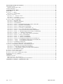
INDEX
LAYOUT ......................................................................................................................................................................... 5
STORAGE ....................................................................................................................................................................... 5
INSTALLATION NOTE ................................................................................................................................................ 6
PRELIMINARY OPERATIONS .................................................................................................................................. 6
INSTALLATION ROOM................................................................................................................................................ 6
POSITIONING .............................................................................................................................................................. 7
SETTING UP THE ELECTRICAL SYSTEM ............................................................................................................. 7
PROTECTIONS ................................................................................................................................................................ 7
Inside the UPS............................................................................................................................................................... 7
UPS Input...................................................................................................................................................................... 7
UPS output, Short circuits and selectivity..................................................................................................................... 7
Differential .................................................................................................................................................................... 8
CONNECTIONS ............................................................................................................................................................. 8
PRELIMINARY OPERATIONS FOR OPENING UPS...................................................................................................... 8
MAINS AND LOAD CONNECTIONS............................................................................................................................... 9
Single phase output ...................................................................................................................................................... 9
Threephase output (input threephase only)................................................................................................................. 10
BATTERIES CONNECTIONS......................................................................................................................................... 10
Internal battery cabinet............................................................................................................................................... 10
External battery cabinet.............................................................................................................................................. 10
REMOTE CONTROL AND SIGNALS............................................................................................................................. 11
EPO connector, Emergency power off (pos. A) .......................................................................................................... 11
15-pin female marked REMOTE................................................................................................................................. 11
SYSTEM OFF (the Command is memorised)............................................................................................................ 11
RS232 .......................................................................................................................................................................... 11
SNMP connector, Simple Network Management protocol (optional)......................................................................... 12
CHECKING CONNECTIONS......................................................................................................................................... 12
START-UP PROCEDURE........................................................................................................................................... 12
OPERATIONAL CHECK ................................................................................................................................................ 13
SET UP / CUSTOMISATION.......................................................................................................................................... 13
SWITCHING OFF........................................................................................................................................................... 14
CONFIGURATION MODES........................................................................................................................................... 14
ON - LINE ................................................................................................................................................................... 14
STANDBY-ON operation ............................................................................................................................................ 14
STAND-BY OFF.......................................................................................................................................................... 15
STABILIZER (without battery).................................................................................................................................. 15
MODES OF OPERATIONS ............................................................................................................................................ 16
BATTERY operation (no in STABILIZER MODE)...................................................................................................... 16
Operation of the BY-PASS network............................................................................................................................. 16
BYPASS for maintenance SWMB ................................................................................................................................ 16
MAINTENANCE .......................................................................................................................................................... 17
UPS COMPONENTS ................................................................................................................................................... 17
Input / Output filter ..................................................................................................................................................... 17
Converter .................................................................................................................................................................... 18
Inverter........................................................................................................................................................................ 18
Static By-pass.............................................................................................................................................................. 18
SWMB (maintenance switch), SWIN, SWOUT ........................................................................................................... 18
Battery......................................................................................................................................................................... 18
RS232 n.1 and n. 2 interface....................................................................................................................................... 18
Signallings and command panel ................................................................................................................................. 18
EPO connector (Emergency power off) normally closed contact ............................................................................... 18
Harmonic compensator (optional) .............................................................................................................................. 18
SPECIFICATIONS....................................................................................................................................................... 20
SYSTEM .......................................................................................................................................................................... 20
CONVERTER INPUT.................................................................................................................................................. 20
CONVERTER OUTPUT.............................................................................................................................................. 21
BATTERY .................................................................................................................................................................... 21
OUTPUT INVERTER.................................................................................................................................................. 21
BYPASS LINE ............................................................................................................................................................. 21
0MNAMS1NEB
pag. 3 / 43
SIGNALLING PANEL FUNCTIONS.........................................................................................................................22
General Description ........................................................................................................................................................22
Luminous warning lights: LED. ..................................................................................................................................22
ALARM MESSAGes........................................................................................................................................................23
CONTROL PANEL MENU .........................................................................................................................................25
BASIC MENU..................................................................................................................................................................25
Key menu 1, "?", HELP...................................................................................................................................................26
Key menu 1, 1: LANGUAGES .....................................................................................................................................27
Key menu 2 "measures"...................................................................................................................................................27
Key menu 2, 2 : “Measures output”..........................................................................................................................28
Key menu 2, 2, 2 : measures........................................................................................................................................28
Key menu 2, 6: TIME MEASUREMENT .....................................................................................................................29
Key menu 3 "KEY", COMMANDS ..................................................................................................................................29
Key menu 3, 2: BATTERY TEST..................................................................................................................................29
Key menu 3, 4: DISPLAY CONTRAST........................................................................................................................30
Key menu 3, 5: CUSTOMIZING..................................................................................................................................30
Key menu 3, 5, 436215, 2: CUSTOMIZING RATED OUTPUT VOLTAGE ...............................................................30
Key menu 3, 5, 436215 ,3: BATTERY CUSTOMIZING ..............................................................................................31
Key menu 3, 5, 436215 4: PREALARM CUSTOMIZING ..........................................................................................31
Key menu 3, 5, 436215 6: AUTO-OFF CUSTOMIZING “VA”.................................................................................32
Key menu 3, 5, 436215, 6, 5 (6): AUTO-OFF Timer CUSTOMIZING .......................................................................32
Key menu 3, 5, 436215, 7, 2: BYPASS VOLTAGE RANGE CUSTOMIZING.............................................................33
Key menu 3, 5, 436215, 7, 3: BYPASS FREQUENCY RANGE CUSTOMIZING ......................................................33
Key menu 3, 5, 436215, 7, 4 : MODEM CUSTOMIZING.........................................................................................33
Key menu 3, 5, 436215, 7, 4, 5 (6) : Modem 'Dial /Send' CUSTOMIZING. ..............................................................34
Key menu 3, 5, 436215, 7, 5: RS232 CUSTOMIZING ................................................................................................34
Key menu 3, 5, 436215, 7, 6: ECHO CUSTOMIZING...............................................................................................34
Key menu 3, 5, 436215, 7, 7: IDENT. CUSTOMIZING .............................................................................................35
Key menu 3, 5, 436215, 8: CUSTOMIZING OPERATION IN STANDBY ON............................................................35
Key menu 3, 5, “642137” : CUSTOMIZING OPERATION IN STANDBY OFF. ......................................................35
Key menu 3, 5, “156234” : CUSTOMIZING STABILIZER . .....................................................................................35
Key menu 3, 6: INVERTER-OFF/BYPASS..................................................................................................................35
Key menu 3, 7: TOTAL SYSTEM SHUT-OFF COMMAND........................................................................................36
Key menu 4: "RECORDER": HISTORY = RECORDED EVENTS.................................................................................36
Key menu 4, 2 RECORDED VOLTAGES MEASUREMENT ......................................................................................36
Key menu 4, 2, 2: RECORDED CURRENT MEASUREMENT...................................................................................36
Key menu 4, 2, 2, 2: RECORDED 3-PHASE VOLTAGE MEASUREMENT...............................................................37
Key menu 4, 6: RECORDED CODES .........................................................................................................................37
Key menu 5: Acoustic alarm exclusion ...........................................................................................................................37
Key menu 6: "clock": DATE/TIME .................................................................................................................................37
Key menu 7 "arrow down": INTERNAL CODES ............................................................................................................38
Key menu 8 "arrow up": NORMAL.................................................................................................................................38
APPENDIX ....................................................................................................................................................................39
INTERNAL LAYOUT.......................................................................................................................................................39
Battery Pack Ups / Pacchi Batteria............................................................................................................................41
Battery Plate Connections / Collegamenti Vassoio Batteria.......................................................................................42
DIMENSION WEIGHT / DIMENSIONI PESI.....................................................................................................43
pag. 4 / 43
0MNAMS1NEB
ENGLISH
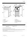
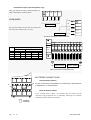
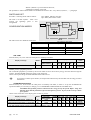
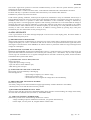
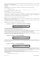
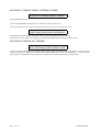
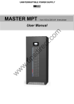
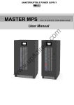
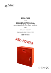
LAYOUT
11
1
10
2
12
9
2
8
1
13
3
7
6
14
5
3
4
4
14
1.
2.
3.
4.
5.
6.
7.
control panel;
top panel;
front panel;
wheels for the movement;
rear ventilation holes;
rear income cables;
heat sinks;
8.
9.
10.
11.
12.
13.
14.
fan grid;
EPO connector;
REMOTE connector;
RS232-2 communications port;
RS232-1 communications port;
Communications-card option;
Side panel;
STORAGE
The area used to store the equipment must have the following characteristics:
Temperature:
0°÷40°C (32°÷104°F)
Relative humidity:
95% max
Only for UPS with internal BATTERIES.
The batteries contained in the UPS are subject to self-discharging.
If the UPS is not immediately installed is necessary to take note of the batteries date recharge printed on the label
fixed to the packing case (the date is present only if the UPS contains to its inside batteries), and provide to it
recharges within such date.
To recharge batteries just power up the UPS and leave it on NORMAL OPERATION for at least 24 hours.
For advanced storage periods to contact the service assistance.
0MNAMS1NEB
pag. 5 / 43
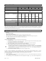
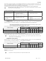
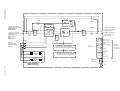
INSTALLATION NOTE
rated power
operating temperature
relative humidity max.
maximum operating altitude.
[kVA]
SINGLE PHASE OUTPUT
10
15
20
THREE PHASE OUTPUT
10
15
20
30
0 ± 40 °C
95 % (without condensate)
1000 m at rated power (-1% rated power for each 100m over 1000m), max
4000m
450 x 750 x 1200
dimensions (L x D x H)
[mm]
UPS weight (version with harmonics
reduction filter)
without battery 112 (152) 122 (167) 123 (173) 114 (154) 122 (167) 124 (174) 144 (204)
206 (246) 261 (306)
7Ah 204 (244) 260 (305)
277 (327)
276 (326)
9Ah
12Ah 250 (290) 328 (373) 329 (379) 251 (291) 328 (373) 330 (380)
370 (430)
14Ah
loss power with nominal load and battery
0,7
1,04
1,39
0,7
1,04
1,39
2,1
charge.
600
900
1200
600
900
1200
1800
[kW / kcal /B.T.U.] 2400
3600
4800
2400
3600
4800
7100
flow rate allowing (for room installation)
(*)
[mc/h]
370
557
742
370
557
742
1100
leakage current (mA) max:
< 100 mA
Degree of protectio
IP20
Cable input
from the bottom / rear
(*) To calculate the air flow rate the following formula can be used: Q (m3/h) = 3.1*pdiss(kcal) / (ta-te) (°C)
Pdiss is the power dissipated expressed in kcal in the installation environment by all the installed equipment.
ta=ambient
temperature, te=outside temperature.To allow for losses the value taken should be increased by 10%. In the table in the appendix is
shown an example of flowrate allowing a (ta-te) of 5°C.
PRELIMINARY OPERATIONS
The UPS is delivered with:
- guarantee
- user instruction manual
- Cd-rom with the UPS software
- Jumper to short-circuit the input terminals (only for single-phase output version)
- Nr. 3 input battery fuse, for position see APPENDIX, INTERNAL LAYOUT pos.2 (pag. 39, pag. 40)
- Nr. 2 battery pack fuse (only if internal battery are present pag. 10)
INSTALLATION ROOM
When choosing a suitable installation room, take note of the following:
•
avoid dusty areas,
•
check that the floor is plane level and strong enough to support the weight of the UPS and the battery cabinet
(see paragraph "DIMENSIONS AND WEIGHTS")
•
avoid rooms that are too narrow as this could make normal maintenance operations difficult
•
relative room humidity must be lower than 95%, without condensate
•
check the ambient temperature when the UPS is running. It should be between 0 and 40°C
The UPS is able to function in an ambient temperature of between 0 and 40°C. The recommended
operating temperature for the UPS and the batteries is between 20 and 25°C. In fact, the average operating
life of the batteries is 4 years at an operating temperature of 20°C, but if the operating temperature is
increased to 30°C the life is halved.
•
do not position the machine in areas exposed to direct sun light or hot air.
In order to keep the temperature of the installation room within the field of values mentioned above, it will be
necessary to install a system for eliminating dissipated heat (the value of the kcal/kW/B.T.U. dissipated by the UPS is
indicated in the paragraph "SPECIFICATIONS”). The following methods can be used:
•
natural ventilation;
•
forced ventilation, recommended if the exterior temperature is lower (e.g. 20°C) than the temperature at which you
wish to run the UPS (e.g. 25°C);
•
air conditioning system, recommended if the exterior temperature is higher (e.g.s.30°C) than the temperature set
pag. 6 / 43
0MNAMS1NEB
ENGLISH
for running the UPS (e.g.s.25°C).
POSITIONING
You should bear in mind the following points when positioning the UPS:
•
a space of at least one metre must be kept in front of the machine to leave plenty of room for maintenance
operations.
•
a space of at least 20 cm. must be left between the back of the UPS and the wall so as not to block the flow of air
from the fans.
•
a space of at least 40 cm. must be left on the side of the UPS, for maintenance operations.
The AC-DC INPUT/OUTPUT cables may enter from the bottom or the rear of the UPS.
SETTING UP THE ELECTRICAL SYSTEM
PROTECTIONS
Inside the UPS.
The size of the switches and fuses installed on the UPS input/output lines are given below (consult the block diagrams
paragraph for the initial). A fuse must always be replaced by a fuse of the same capacity and with the same
characteristics as those mentioned in the table.
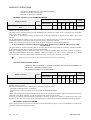
SINGLE PHASE OUTPUT UPS:
Switch and internal protections
UPS
type
[kVA]
switch
fuses
UPS output / Maintenance
10
Input
UPS
SWIN
63A(4P)
Rectifier input
fuse
Battery fuse
Bypass fuse
Input curr.
SWOUT/SWMB
63A (2P)
FBAT
FBY
20AgR(10x38) 30A gR(10x38) 50A gG(14x51)
15
100A(4P)
100A (2P)
30AgR(10x38) 30A gR(10x38) 63A gG(22x58)
67
65
20
100A(4P)
100A (2P)
30AgR(10x38) 30A gR(10x38) 100A gG(22x58)
74
87
max
51
Out.curr.
[A]
Nominal
43
THREE PHASE OUTPUT UPS:
Switch and internal protections
UPS
type
[kVA]
switch
fuses
UPS output / Maintenance
10
Input
UPS
SWIN
32A(4P)
Rectifier input
fuse
Battery fuse
Bypass fuse
Input curr.
SWOUT/SWMB
32A(4P)
FBAT
FBY
20AgR(10x38) 30A gR(10x38) 20A gG(10x38)
max
18
Out.curr.
[A]
Nominal
14
15
32A(4P)
32A(4P)
30AgR(10x38) 30A gR(10x38) 32A gG(10x38)
26
26
20
32A(4P)
32A(4P)
30AgR(10x38) 30A gR(10x38) 32A gG(10x38)
35
35
30
63A(4P)
63A(4P)
50AgR (14x51) 50A gR(14x51) 50A gG(14x51)
52
44
UPS Input.
When selecting the protections to install at the input of the continuity group, you must take into consideration the
maximum current absorbed in the two operating conditions:
•
•
In "NORMAL OPERATION", from the main line via the rectifier, the “max input current” is the one indicated in
the table. The non automatic switch is present at the rectifier input, as shown in the table, "SWIN".
"BY-PASS OPERATION", straight from the by-pass line, the max. value of the current is restricted by
intervention of the “automatic breaker SWBY”.
UPS output, Short circuits and selectivity.
Nominal current, In, output from the UPS is the one indicated in the table "output current".
Short circuit
When a fault occurs on the load, i.e. a short circuit, the UPS protects itself by restricting the value and the duration of
the supplied current (short circuit current). These values also depend on the operating status of the unit at the time of
the fault. We must distinguish between two situations:
•
UPS in NORMAL OPERATION
the load is immediately switched onto the by-pass line, guaranteeing, before the fuses intervene, the
circuit current values indicated in “SPECIFICATION BY_PASS LINE” paragraph.
• UPS in BATTERY OPERATION
The UPS protects itself by supplying an output current approximately double the nominal current for 0,5s,
0MNAMS1NEB
pag. 7 / 43
the output UPS is stop after this time.
Selectivity
In NORMAL OPERATION selectivity is carried out with a fuse indicated in the line two of the table, if you want to
guarantee selectivity when operating by battery also see the line one of the table.
KVA
max. current fuse gG/aM in UPS output [A]
single phase output UPS
10
15
20
gG aM gG aM gG aM
10
gG aM
1) for selectivity in battery operation
2) for selectivity in normal operation
10
32
6
10
6
16
16
40
8
20
20
63
10
36
4
6
three phase output UPS
15
20
30
gG aM gG aM gG aM
6
20
4
10
10
20
6
10
10
32
6
16
Differential
In the standard version, where there is no separation transformer on the by-pass line, the neutral output from the mains
is connected to the output from the UPS.
INPUT NEUTRAL CONNECTED TO OUTPUT NEUTRAL
THE ELECTRICAL SYSTEMS LOCATED UPSTREAM AND DOWNSTREAM OF THE UPS ARE IDENTICAL
When operating in the presence of mains voltage, a differential breaker installed at the input intervenes because the
output circuit is not isolated from the input circuit.
In any case it is always possible to install more differential breakers at the output, possibly co-ordinated with those at
the input.The differential switch located upstream must have the following characteristics:
a minimum differential current of 100mA (to avoid inappropriate interventions)
class A or class B
delay greater or equal to 0,1s
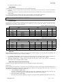
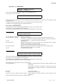
CONNECTIONS
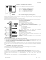
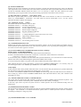
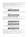
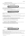
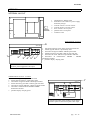
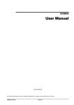
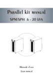
PRELIMINARY OPERATIONS FOR OPENING
UPS
A
E
B
A ssiem e m acchina
The following operations are to be performed with the UPS
disconnected from the mains and all the equipment switches open
(control lever down).
Following the following instructions to open the UPS:
D
A)
B)
C)
D-E)
Open the covers display panel (A).
Remove the covers switches panel (B)
Remove the rounded front panel rising toward the high
(C)
covers display panel
covers switches panel
rounded front panel
unscrew to remove side panels
C
THE FIRST CONNECTION TO MAKE IS THE GROUNDING LEAD TO THE TERMINAL MARKED 'PE'.
THE UPS CANNOT OPERATE WITHOUT CONNECTION TO THE GROUNDING SYSTEM.
pag. 8 / 43
0MNAMS1NEB
ENGLISH
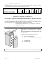
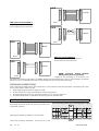
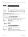
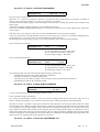
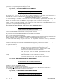
MAINS AND LOAD CONNECTIONS
Single phase output
input singlephase with neutral
The UPS MUST NOT BE USED WITHOUT A INPUT
NEUTRAL CONNECTION.
Short-circuit the input Terminals, L1, L2, L3 with the jumper
available, as shown in figure.
For input and output wire size refer to the following table (between
brackets max. wire size):
PE
Sez. [mmq]
OUTPUT
N
PE
L1/N
10(50)
10(50)
10(50)
16(50)
16(50)
16(50)
25(50)
16(50)
25(50)
L1 L2
L3
N
N
L
PE
INPUT
kVA
10
15
20
L1
10(50)
16(50)
25(50)
L
PE
N
L
N
PE
Ingresso/Input
Uscita / Output
10-20kVA single phase output terminals
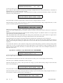
input three phase with neutral
The UPS MUST NOT BE USED WITHOUT A INPUT NEUTRAL CONNECTION.
For input and output wire size refer to the following table
(between brackets max. wire size):
Sez. [mmq]
INPUT
OUTPUT
PE L1 L2
L3
N
kVA L1 L2/L3
N
PE
L1/N
10 10(50) 4(50) 10(50) 10(50) 10(50)
15 16(50) 6(50) 16(50) 16(50) 16(50)
20 25(50) 10(50) 25(50) 16(50) 25(50)
L1
L2
L3
PE
N
L
N
L
PE
N
PE
Ingresso/Input
Uscita / Output
10-20kVA single phase output terminals
:
0MNAMS1NEB
pag. 9 / 43
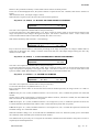
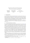
Threephase output (input threephase only)
THE UPS MUST NOT BE USED WITHOUT A
INPUT NEUTRAL CONNECTION.
PE
N
L3
L2
L1
10,20,30kVA
PE
N
L3
L2
PE
L1
Ingresso/Input
For input and output wire size refer to the following
table (between brackets max. wire size):
Uscita / Output
PE
N
N
L3
L3
L2
L2
L1
L1
- 10-20kVA threephase output terminals
PE L1 L2 L3
Sez. [mmq]
INGRESSO
USCITA
kVA L1/L2/L2 N
PE
L1/L2/L3 N
10
4 (10) 4 (10) 4 (10)
4 (10) 4 (10)
15
6 (10) 6 (10) 6 (10)
6 (10) 6 (10)
20
10 (10) 10 (10) 10 (10) 10 (10) 10 (10)
30
16(50) 16(50) 16(50)
16(50) 16(50)
N
L1 L2 L3
N PE
N
L1
N
FBAT
N
L1
PE
L2
L3
Ingresso/Input
L2
L3
Uscita / Output
PE
- 30kVA threephase output terminals
BATTERIES CONNECTIONS
+
+
+
+
Internal battery cabinet
A
+
+
FUSE
+
+
+
B For the versions with inner batteries, it is necessary to insert the fuse
in equipment in A and B position.
FUSE
+
+
+
External battery cabinet
In the external battery cabinet the batteries must be inserted and be
connected, using appropriate kit in equipment, following the procedure
indicated on battery cabinet user manual.
FRONT
FRONTE
pag. 10 / 43
0MNAMS1NEB
ENGLISH
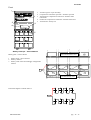
REMOTE CONTROL AND SIGNALS
E
In the rear of the UPS there are the following connectors:
A B C D
pos A - EPO connector, Emergency power off;
pos B -Nr. 1 DB15 female marked REMOTE;
pos C - Nr. 1 DB9 male marked RS232-2;
pos D - Nr. 1 DB9 female marked RS232-1;
pos E - Nr. 1 SNMP connector (optional).
REAR
RETRO
EPO connector, Emergency power off (pos. A)
When the jumper on the EPO connector is opened the UPS output voltage is interrupted. The UPS factory supplied
with the E.P.O. connectors short-circuited.
Pressing a button is therefore possible remove UPS output voltage
Removing only the feeding, for instance opening the UPS input switch, the UPS would feed the load with the batteries.
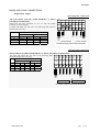
15-pin female marked REMOTE.
On the connector there are:
aux power 12Vdc 80mA(max), pin 1 ad 15;
Nr. 3 voltage free exchange contacts for alarms;
Nr. 2 remote Controls for turning off INVERTER and UPS.
The pin arrangement of the connector is as follows (see figure
opposite):
BATTERY LOW
BATTERY DISCHARGING
BY-PASS/FAULT
The contact positions shown are without alarm (NORMAL
OPERATION).
The relay contacts can carry a current of 0.5A-42V.
REMOTE COMMANDS
Two commands are available as follows:
BY-PASS with STOP INVERTER command. Connecting pin 8 to pin
15 (after at least 2 seconds).
SYSTEM OFF command. Connecting pin 7 to pin 15 (after at least 2
seconds).
BY-PASS with STOP INVERTER ( the Command it is not memorised)
1. If the UPS receives the INVERTER OFF command when it is in "NORMAL OPERATION" mode, it switches the
load supply onto the BY-PASS line (load unprotected from any mains failure).
2. If the UPS receives the STOP INVERTER command when it is in "EMERGENCY OPERATION" mode, it will
switch itself off (load not fed)
In the two versions seen, if the jumper is maintained when the mains power returns the UPS will continue operating on
the by-pass line. However, if the jumper has been removed, the UPS will start up again in NORMAL OPERATION
mode.
SYSTEM OFF (the Command is memorised).
If the UPS receives the SYSTEM OFF command it will cut off the output voltage. LOAD NOT FEED.
To start up the UPS again, send INVERTER OFF command.
RS232
Two connectors for the connection are available The transmission protocol pre-set at the UPS factory is as follows:
9600 baud, -no parity, -8bit, -1 bit of stop.
Transmission speed can be changed from 1200 to 9600 baud on the CUSTOMISE menu on the panel. Recommended
transmission speeds for various distances are as follows:9600(baud) 50m, 4800 100m, 2400
200m, 1200
300m
Use shielded cable, connect the shield only to the housing of the MODEM connector, AWG22-AWG28.
0MNAMS1NEB
pag. 11 / 43
UPS
1
2
3
4
1
2
3
4
1
2
3
4
1
2
3
4
5
6
7
8
5
6
7
8
5
6
7
8
5
6
7
8
9
female
femmina
DB9
DB9 female marked RS232-1
To use for,pin to pin, PC connection.
See the fugure for the connections.
UPS
9
male
maschio
DB9
1
2
3
4
1
2
3
4
1
2
3
4
1
2
3
4
5
6
7
8
5
6
7
8
5
6
7
8
5
6
7
8
9
9
9
male
maschio
DB9
male
maschio
DB9
Modem
9
female
femmina
DB9
RS232-1
1
2
3
4
5
6
7
8
9
male
maschio
db9
1
2
3
4
5
6
7
8
9
female
femmina
db9
1
2
3
4
5
6
7
8
9
male
maschio
db9
1
2
3
4
5
6
7
8
9
Modem
female
femmina
db9
RS232-2
UPS
9
female
femmina
DB9
RS232-1
female
femmina
DB9
UPS
9
male
maschio
DB9
computer
DB9 male marked RS232-2
To use for, pin to pin, modem connection..
See the fugure for the connections.
1
2
3
4
5
6
7
8
9
male
maschio
DB9
1
2
3
4
5
6
7
8
9
female
femmina
DB9
1
2
3
4
5
6
7
8
9
female
femmina
DB9
1
2
3
4
5
6
7
8
9
Computer
male
maschio
db9
SNMP connector, Simple Network
Management protocol (optional)
RS232-2
Lodging for the positioning of an electronic card
that allows the insertion of the UPS a net SNMP (Simple Network Management protocol), with possibility to transmit
data and to receive commands from a station of control that can be in an any part of the world.
CHECKING CONNECTIONS
After connecting the INPUT/OUT and terminal wires to the terminals of the UPS and before repositioning the switch
covers panel, check to make sure that:
• all the input/output terminals are tightly screwed;
• all fuse holders have a fuse inserted and are in the closed position;
• the input/output protection wire (yellow/green earth wire) is correctly connected
• the internal panel panel is connected to the yellow/green uni-potential cable.
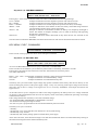
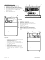
START-UP PROCEDURE
After completing the electrical connection as indicated above
and putting the internal panel into position, proceed to start
up the UPS as follows:
Fuse and switch position of the UPS singlephase output
SWIN
FBAT
AUX
SWOUT
AUX
SWMB
FBY
Following the following operation to start the UPS:
verify that the battery fuseholder
pag. 12 / 43
in the UPS or in the
0MNAMS1NEB
ENGLISH
battery cabinet (if present) are closed;
Fuse and switch position of the UPS threephase output 10-20kVA
verify that the harmonic filter fuseholder are
closed (only if harmonic filter is present);
SWIN
Close the following UPS switches (the label is
given on the switch cover panel):
- FBAT battery fuses
- SWIN input switch,
- FBY by-pass line fuse (fuses for threephase
version),
- SWOUT output switch.
FBAT
SWOUT
SWMB
FBY
NOTE: the SWMB switch must be left open,
FBAT FBAT
FBY
FBY
FBY
SWIN
SWOUT
+
SWMB
during normal operation. The SWMB is
closed only in order to directly feed the mains
load excluding the UPS, e.g. for maintenance
FBAT
purposes
(see
chapter
OPERATING
Fuse and switch position of the UPS threephase output 30kVA
MODES).
After you have carried out the abovementioned operations, you will immediately
FBAT
hear the hum of the fans, and for about one
N
minute, the noise of the buzzer. Press button 1
twice, select the language and then press
button 8, to return to the base menu. The
message NORMAL OPERATION will
appear. Carry out the battery test manually: press button 3 on the display panel, and then button 2 (BATTERY TEST).
When the test is finished and the UPS is correctly started up, with the battery connected, the green IN LED (INPUT)
and the green OUT LED (OUTPUT) lights should be lit without flashing.
The message NORMAL OPERATION should appear on the first line of the panel. The model of the UPS, according to
the following code, will appear on the second line in the left-hand corner:
--
-- -- --
Nominal Power [kVA]
UPS model
OPERATIONAL CHECK
After completing the start-up operations and waiting for at least four hours to allow the batteries to charge, with the
UPS in normal operation, a Mains failure simulation may be carried out using the switch positioned above the
continuity unit. You will hear the sound of the buzzer (with 5=ON)1 while on the Signal and Commands Panel the
green LED OUT .and the yellow LED are lit without flashing.
Check that the power supply to the UPS is working. In this situation, Mains power failure, the energy supplied to the
load is that which has previously been accumulated in the batteries. After a few minutes with the power supplied by the
batteries you can return to normal operation condition by closing the input switch. The control Panel will indicate this
by turning on the green LEDs IN and OUT. The re-charging of the batteries will happen automatically.
SET UP / CUSTOMISATION
By inserting the access code 436215, using the COMMAND PANEL ( from the main MENÙ press keys 3
"COMMANDS" and then 5 " CUSTOMISING" ), it is possible modify UPS working mode (see "MODES OF
OPERATION" paragraph) and alter some of the electric parameters pre-set in the factory, within a certain field:It is
possible to customise the following values:
- value of the NOMINAL OUTPUT VOLTAGE;
- voltage field and the frequency of acceptance on the BY-PASS line;
- voltage field and the frequency of acceptance on the BY-PASS line in Stand-by ON mode;
- BATTERY parameters, pre-alarm for final battery discharge;
- UPS out on By-pass line when output power lower than a set value (AUTO-OFF power);
- daily scheduled shut-off (AUTO-OFF time);
1
Check the status of the buzzer, in the second line on the right of the display panel:
“5=OFF” buzzer disabled,
“5=ON” buzzer enabled,
press button 5 to change the status.
0MNAMS1NEB
pag. 13 / 43
- RS232-1, RS232-2 port trasmission baud rate;
- identification number of the UPS.
The procedure to follow and the fields to be modified are shown in the “”key menu 3,5,436215,…..” paragraph.
SWITCHING OFF
Proceed to switching off the UPS as follows:
open SWIN, SWOUT switches;
open FBY, FBAT fuses holder.
The load is not fed anymore. After a few
seconds the signalings panel is also
extinguished
Converter
INPUT
Inverter
CONFIGURATION MODES
LOAD
Battery
UPS
The UPS can be set in different mode of use:
Configuration mode
The LOAD is feed from:
with INPUT present
INPUT failure
- ON-LINE;
- STAND-BY ON.
- STAND-BY OFF
- STABILIZER
inverter
INPUT
not fed
Inverter
ON - LINE
With the factory set, to the starter the UPS places in modality ON LINE.
switch position
Display message
INPUT
NORMAL OPERATION
ok
SWIN/FBY/
FBAT/SWOUT
close
Inverter
Inverter
Inverter
not fed
Display status
LOAD
SWMB Led
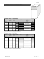
Led Led Led Buzz
BATT IN OUT BY
er
open
off
on
on
off
off
Fed from
INVERTER
MAINS present, equipment powered.
The connected equipment is powered by the inverter which receives the necessary energy from the mains through the
rectifier. The RECTIFIER charges the battery at the same time.
On the control panel the green LEDS MAINS and OUTPUT are lit.
In presence of a mains power failure, the output load remains fed by the UPS that uses the energy stored in
the batteries.
STANDBY-ON operation
With the factory set, to the starter the UPS places in modality ON LINE, in order to set up the STANDBY-ON
operation modality it is necessary to read pag. 35 “CUSTOMIZING OPERATION IN STANDBY ON”.
STANDBY-ON operation permits a reduction in the energy lost by the system. Before using this
function check that the fed load accepts an interruption of 2-5 ms. in feed, in the event of a mains
power failure.
On the in the second line of the display panel N letter is present.
switch position
Display panel status
LOAD
Display message
INPUT
SWIN/FBY/
SWMB Led Led Led Led Buzz
FBAT/SWOUT
BATT
IN
OUT
BY
er
NORMAL OPERATION STBY-ON
ok
close
open
off
on
on
off
off
MAIN LINE VOLTAGE FAIL or SWIN OFF
ko
close
open
on
off
on
off
on
Fed from
INPUT
Fed from
INVERTER
The RECTIFIER remains turned on and maintains the battery charge.
pag. 14 / 43
0MNAMS1NEB
ENGLISH
The inverter to by-pass line transfer can be immediate (planned time =0) or delayed (maximum of 180 minutes), see
menu’ “CUSTOMIZING OPERATION IN STANDBY ON” (N.B. because the passage happens it is necessary that the
line of bypass remains within the values of acceptance for the planned time).
The System remains in this state until voltage and frequency of the BY-PASS line are within acceptable limits.
If the BY-PASS line lacks voltage or the frequency goes outside acceptable limits, the load is switched
automatically to the INVERTER output.
advantages and disadvantages of the two ways of operation (ON LINE or STAND-BY ON):
advantages
disadvantages
- inverter always feeds load with voltage - power lost, UPS efficiency with
comparison between ONnominal load is 92÷93%,
and frequency stabilized,
LINE and STAND-BY ON
- transfer time to battery operation equal
mode
zero,
- power factor corrector to the main line
- reduced power lost , UPS efficiency - Load is feed from mains voltage and
comparison between
with INPUT present is 98%.
frequency,
STAND-BY ON and ON- transfer time to battery operation not
LINE mode
equal zero
STAND-BY OFF
With the factory set, to the starter the UPS places in modality ON LINE, in order to set up the STANDBY-OFF
operation modality it is necessary to read pag. 35 “ CUSTOMIZING OPERATION IN STANDBY OFF ”.
With UPS in STAND BY OFF mode and mains input is present the UPS voltage output is equal to
zero. The output load is feed only when input voltage is failure.
On the in the second line of the display panel F letter is present.
switch position
Display panel status
LOAD
Display message
INPUT
SWIN/FBY/
FBAT/SWOUT
NORMAL OPERATION STBY-OFF
MAIN LINE VOLTAGE FAIL or SWIN OFF
ok
ko
close
close
SWMB Led
BATT
open
open
off
on
Led Led Led Buzz
IN OUT BY
er
on
off
off
on
off
off
off
on
Not fed
Fed from
INVERTER
The RECTIFIER remains turned on and maintains the battery charge.
The UPS output voltage is equal to 0V until voltage and frequency of the BY-PASS line are within acceptable limits.
If the BY-PASS line lacks voltage or the frequency goes outside acceptable limits, the load is feed
automatically to the INVERTER output.
STABILIZER (without battery)
With the factory set, to the starter the UPS places in modality ON LINE, in order to set up the STANDBY-OFF
operation modality it is necessary to read pag. 35 “ CUSTOMIZING STABILIZER ”.
On the in the second line of the display panel S letter is present.
switch position
Display message
INPUT
NORMAL OPERATION
ok
SWIN/FBY/
FBAT/SWOUT
close
Display panel status
LOAD
SWMB Led
Led Led Led Buzz
BATT IN OUT BY
er
open
off
on
on
off
off
Fed from
INVERTER
MAINS present, equipment powered.
The connected LOAD is powered by the inverter which receives the necessary energy from the mains through the
rectifier.
The batteries are not present.
In presence of a mains power failure, the output load remains not fed.
0MNAMS1NEB
pag. 15 / 43
MODES OF OPERATIONS
- BATTERY OPERATION (no in STABILIZER MODE)
- Operation of the BY-PASS network;
- BYPASS for maintenance SWMB;
BATTERY operation (no in STABILIZER MODE)
switch position
Display message
INPUT
MAIN LINE VOLTAGE FAIL or SWIN
OFF
ko
SWIN/FBY/
FBAT/SWOUT
close
Display panel status
LOAD
SWMB Led
Led Led Led Buzz
BATT IN OUT BY
er
open
on
off
on
off
on
Fed from
INVERTER
MAINS off, equipment powered.
The UPS is in this operating condition when MAINS power is lacking in a black out or is no longer in an acceptable
range (over or under voltage).
In this phase of operation the energy required by the connected equipment is supplied by the battery, previously
charged.
On the alphanumerical PANEL on the front of the UPS is displayed the time provided for residual AUTONOMY,
calculated on the basis of the power delivered and the charge status of the batteries.
NOTE. The value displayed is approximate since the power required can change during discharge.
IT IS POSSIBLE TO INCREASE DURATION BY DISCONNECTING SOME OF THE CONNECTED
EQUIPMENT.
The green LEDs for OUTPUT (steady light) are lit on the panel and the yellow LED for the battery (STEADY LIGHT)
at the moment of mains failure sounds the buzzer intermittently.
When the remaining time drops below the preset value as LOW BATTERY alarm, the buzzer increases in frequency
while the yellow BATTERY LED goes to flashing. Under this condition it is wise to save any work under way. When
the mains failure continues and the battery exhausts its energy, the UPS cuts off power to the loads.
Upon return of mains power, the UPS recharges the batteries automatically.
Operation of the BY-PASS network
Temporary State of operation, or permanent operation state caused by a breakdown; in
this last case contact the assistance centre.
The load isn't secured in case of mains failure.
switch position
Display message
BYPASS FOR OUTPUT OVERLOAD
Display panel status
LOAD
INPUT
ok
SWIN/FBY/
FBAT/SWOUT
close
SWMB Led
Led Led Led Buzz
BATT IN OUT BY
er
open
off
on
off
On
or
blink
on
Fed from
bypass
MAINS present, load fed.
The UPS can find itself in this condition due to one of the following events:
- BY-PASS command (manual or automatic)
- excessive load in output (overload, see the paragraph ALARM MESSAGES))
- fault
On the control panel, the green INVERTER output LED is off, the yellow BY-PASS LED will be turned on steady if a
command is present but will flash on and off in the presence of an overload or fault.
In case of a load greater than the nominal (overload) you will have to intervene to reduce it, otherwise the fuse on the
by-pass line will intervene, turning off the output (for times of intervention consult the SPECIFICATIONS paragraph).
BYPASS for maintenance SWMB
Series of operations to be carried out to place the UPS in maintenance by-pass to carry out maintenance operations on
equipment while maintaining the fed load:
pag. 16 / 43
0MNAMS1NEB
ENGLISH
Status I
NORMAL OPERATION
Status II
SWMB switch closed (the control logic automatically disables the inverter).
Status III
All machine switches open. Only the SWMB switch is kept closed (by-pass maintenance line).The signal panel
remains off. With the load powered through the maintenance line (during maintenance) any disturbance such as a
blackout on the power line of the UPS would have repercussions on the powered equipment (under this condition the
operation batteries are desactivated).
When the maintenance operations are concluded restart the UPS: close SWIN, SWBY, SWOUT and then open
SWMB. The UPS will return to NORMAL OPERATION.
MAINTENANCE
CAUTION Maintenance inside the UPS should only be done by qualified personnel. Inside the equipment there are
voltages even with the input and battery switches open. Removal of the side panels of the UPS by unqualified
personnel can cause harm to the operator and damage the equipment.
Preventive Maintenance
The only components of the UPS which require periodic checking are the blowers and batteries.
- Blowers should be checked for correct operation periodically.
- Batteries. CAUTION Any battery replacement should be done by qualified personnel. For disposal of the
replaced parts it is obligatory to deliver them to one of the special consortiums for disposal by recycling. Batteries are
classified 'toxic waste' by law. The system automatically checks battery efficiency every 24 hours and gives an alarm
when it finds efficiency very much lower than that calculated on the basis of memorized capacity (see key menu 3.2
BATTERY TEST). Battery life depends on operating temperature and the number of charging and discharging cycles
performed. Battery life when used at 20°C is approximately 3 to 5 years while duration is halved if operating
temperature goes to 30°C. Capacity is not constant but increases after a few charging and discharging cycles, then
remains constant for several hundred cycles and finally decreases.
Battery maintenance should include: - Holding operating temperature in the range 20-25°C.
- During the first month of use carry out two or three charge/discharge cycles.
- After the first month of use perform this operation every six months.
The battery should be changed if necessary only by qualified personnel. to eliminate replaced parts it is obligatory to
deliver them to one of the special consortiums for disposal by recycling. the batteries are classified toxic waste by law.
UPS COMPONENTS
The UPS consists of the following subassemblies:
- input /output filter (EMI);
- converter;
- inverter;
- by-pass;
- SWMB (maintenance switch), SWIN, SWOUT;
- Battery;
- RS232-1, RS232-2;
- Remote control and signals;
- Signallings and command panel;
- EPO (Emergency Power OFF);
- Harmonic compensator (optional)
Input / Output filter
They eliminate the high frequency disturbance, during the normal operation, protecting the UPS and therefore the uses
connected by the deriving troubles by supply network. They avoid besides that the high frequency present inside the
UPS is propagated to the outside.
In the threephase versions is place on the input/output terminal board while in the singlephase versions is positioned
after the input switch.
In Stand-By On operation, and in " Bypass " the filters always furnish the protection of the uses from the troubles of by
supply network. In the threephase versions the protection is also guaranteed in the condition of Maintenance by-pass
(SWMB close).
0MNAMS1NEB
pag. 17 / 43
Converter
Represents the input stage and transforms the alternating voltage of the power line in continuous voltage.
In Normal Operation it feeds the inverter and charge the battery.
During the input voltage fault it raises battery output voltage to the constant value required by the inverter.
In the singlephase UPS version the converter can indifferently be connected singlephase to a line 230V or threefase
400V with neutral.
The converter is behaved as an PFC (power factor control) the input power factor is very high (0,99 with singlephase
input, 0,95 with threephase input), the UPS is behaved as an power factor corrector with benefits effects on the plant.
Inverter
This is the output stage. Converts direct voltage from the RECTIFIER or BATTERY into stabilized sinusoidal
alternating voltage. In “ON LINE “ mode it is always in operation and the load connected to the output of the UPS is
always powered by the INVERTER.
Static By-pass
This device allows the instantaneous automatic or manual switching of the power feed from the secured line
(INVERTER output ) to an unsecured line (BY-PASS line) or vice versa is realised with SCR that assure the
commutation in time zero. It is able to sustain intolerable overloads for the electronics of the inverter and to also allow
the continuity of the tension exit of the UPS in case of breakdown inside of the same.
In series to the SCRs the protection is inserted against the returns of tension ("back-feed, protection"), to prevent that in
the case of breakdown of the SCRs, there is, during the interruption of the primary feeding, a potential with danger of
electric shake to the clamps of feeding.
To the entry of the line of bypass they are present the fuse FBYs (one in the version singlephase, three in the version
threephase), such fuses protect both the SCRs in the case of short circuit in exit is the line of bypass from prolonged
overloads.
SWMB (maintenance switch), SWIN, SWOUT
Maintenance switch, by closing the SWMB and opening the other switches SWIN, SWBY, SWOUT the UPS is
excluded, maintaining the output feed.
This operation is necessary when you have to carry out maintenance operations inside the equipment, without being
obliged to interrupt the power feed.
With the SWMB closed and all the other switches open, there is no voltage inside the equipment (voltages are present
only in the terminal board area, in the switches area and in input/output filter area in the threephase version).
Battery
Provides the reserve energy for powering the load when there is no power input to the UPS.
The batteries can be lodged into the UPS or, for longer autonomies, in separate battery cabinet.
RS232 n.1 and n. 2 interface
On the UPS (standard version) are present two RS232 DB9 type connector (one male and one female) and one DB15
female for remote control and signals.
Signallings and command panel
Signalling of operational status of the UPS is supplied by:
- a liquid crystal display (LCD) with two lines of 40 characters
- one keyboard with eight keys,
- four warning lights
- an audible signal.
EPO connector (Emergency power off) normally closed contact
When the jumper on the EPO connector is opened the UPS output voltage is interrupted. The UPS factory supplied
with the E.P.O. connectors short-circuited.
Harmonic compensator (optional)
The filter is positioned to the entry of the converter, allows to reduce the input harmonic distortion of the current. It’s
made only for threephase input version. The filter is protected in entry with fuses.
pag. 18 / 43
0MNAMS1NEB
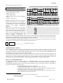
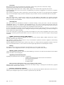
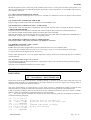
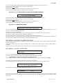
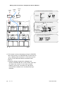
0MNAMS1NEB
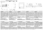
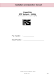
Bypass
FBY
SWMB
TA back-feed
protection
Harmonic compensator/
Compensatore armoniche
Output 3Ph versionn
Versione con uscita 3Ph
Input/ingresso
400V 3Ph+N
L(*)
SWOUT
Optional/Opzionale
SWIN
TLI
- N + Converter
TA out
EMI Filter
Filtro EMI
N
Output 1Ph version
Versione con uscita 1Ph
Input/ingresso
230V 1Ph+N
or / o
400V 3Ph+N
TLR
L(*)
N
EMI Filter
Filtro EMI
EMI Filter
Filtro EMI
Inverter
FBAT
5
13
6
14
Control circuit with processor
Circuiti di controllo con microprocessore
Output 1Ph version
uscita versione 1F
230 1Ph+N
4
12
Optional
external battery
Batterie esterne
opzionali
Output 3Ph version
uscita versione 3F
400V 3Ph+N
DB15
female/femmina
Battery discharge
Batterie in scarica
End Battery discharge
prealarm
Fine scarica batteria
3
Bypass
11
FB01
15
Signallings and command panel
Pannello comandi e segnalazioni
N
-
7
Internal Battery
Batterie interne
Common
Stop UPS
8
FB02
Segnalazioni
e comandi remoti
+12V aux.
(80mA max.)
1
+
Remote control
and signals
10
Stop inverter
DB9
female/femmina
1-9
RS 232-1 line ----------- for PC
DB9
male/maschio
1-9
RS 232-2 line ----------- for Modem
1
2
EPO
ENGLISH
pag. 19 / 43
L1,L2,L3 In the threephase version / nella versione trifase L1,L2,L3.
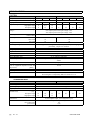
SPECIFICATIONS
SYSTEM
rated power
rated voltage
output power
output active power
[kVA]
[kVA]
[kW]
singlephase input
threephase input
output power function minimum input
voltage
SINGLEPHASE OUTPUT
10
15
20
400V 3F+N o 230V 1F
10
15
20
8
8
efficiency (STANDBY-ON)
load 0÷100%
“ON LINE”
100% load
50% load
leakage current (mA) max:
remote signalling
10
10
THREEPHASE OUTPUT
15
20
30
400V 3F+N
15
20
30
10,5
12
12
16
8
12
16
100% output power with input voltage –20%
60% output power with input voltage –30%
40% output power with input voltage –40%
98%
24
efficiency nominal load
remote command
emergency off
computer/modem interface
SNMP interface
operating temperature
relative humidity max.
maximum operating altitude
cooling
acoustic noise, as measured at 1m from
front of equipment (depend on load and
temperature)
[dBA]
protection degree
cable input
applicable standards
93
91
92
90
< 100 mA
three voltage free exchange contacts (battery low, battery discharging, bypass/fault), output 12V dc 80mA
By-pass and SYSTEM OFF
EPO
Nr 2 RS232/C
optional
0 ± 40 °C
95 % (without condensate)
1000 m at rated power (-1% rated power for each 100m over 1000m), max
4000m
Forced ventilation (fan speed function of the load)
50÷56
IP20
Botton / rear
Safety EN 50091-1-1,
Electromagnetic Compatibility EMC EN 50091-2 Liv.A
SCR BACKFEED PROTECTION
standard
CONVERTER INPUT
rated power (kVA)
rated voltage
Input frequency
frequency tolerance
Max input current with min voltage (with
nominal load)
[A]:
threephase input
singlephase input
current distortion
power factor
UPS with harmonic filter
current distortion
power factor
pag. 20 / 43
SINGLEPHASE OUTPUT
THREEPHASE OUTPUT
10
15
20
10
15
20
30
± 20 % at nominal load
50 / 60 Hz auto learning
45 ÷ 65
18
51
26
35
18
26
35
67
74
27 % threephase input / 7 % singlephase input
0,95 threephase input, 0,99 singlephase input
Input threephase only
9%
0,99
50
0MNAMS1NEB
ENGLISH
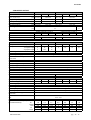
CONVERTER OUTPUT
SINGLEPHASE OUTPUT
10
15
20
maintenance voltage
(20°C, 2,26 x el)
[V]
charge voltage (2,3 x el)
[V]
max output voltage
[V]
ripple voltage
[V]
max charge voltage
[V]
max charge current with nominal load
[A]
BATTERY
type
element number (12V each element)
total rated voltage
[V]
OUTPUT INVERTER
rated power
active power
[kVA]
[kW]
threephase input
singlephase input
rated voltage
[V]
rated current
[A]
phase voltage setting (phase-neutral)
load crest factor at rated power
(Ipeak/Irms)
wave form
distortion with linear load
stability voltage at steady state
stability voltage at transient state
frequency stability: with synchronisation
without synchronisation
overload
short circuit current for 0,5s
Inverter efficiency %
100% load
BYPASS LINE
rated power [kVA]
rated current [A]
rated voltage [V]
Number of phase
input voltage tolerance
rated frequency
input frequency tolerance
stand-by on/inverter typical transfer
switch time
overload/fault inverter transfer switch
time
by-pass fuse type
by-pass line overload capacity
(x nominal current)
1h
10min.
1min
1s
10ms
0MNAMS1NEB
-217+217
-221+221
10
THREEPHASE OUTPUT
15
20
30
-222,5+222,5
-325+325
-331+331
-334+334
-217+217
-221+221
-222,5+222,5
-222,5+222,5
-334+334
-222,5+222,5
-325+325
-331+331
-334+334
< 1%
-334+334
1,5
4
SINGLEPHASE OUTPUT
THREEPHASE OUTPUT
10
15
20
10
15
20
30
Lead sealed battery
16+16
24+24
16+16
24+24
-192+192
-288+288
-192+192
-288+288
SINGLEPHASE OUTPUT
10
15
20
8
8
43
10
THREEPHASE OUTPUT
15
20
30
12
16
8
12
16
10,5
12
230
400
65
87
14
22
29
200 ÷ 250 V , phase neutral (control panel)
3:1
24
43
Sinusoidal
2%
±1%
±5%
±2 % ( settable ± 1 %, ± 5% control panel)
± 0,05 %
110 / 125 / 150 % rated current 300’ / 10’ / 1’
200%
94
93
SINGLEPHASE OUTPUT
THREEPHASE OUTPUT
10
15
20
10
15
20
30
43
65
87
14
22
29
43
230
400
1+N
3+N
±15 % ( settable ± 5 % , ± 25 % control panel)
50 / 60 Hz (auto learning )
±2 % ( settable ± 5 % control panel)
2 ms
50 / gG
63 / gG
100 / gG
1,6
1,8
2,8
5,1
20
1,4
1,6
2,6
5,4
20
1,7
1,9
2,9
7,4
28
0 ms / 1ms
20 / gG
32 / gG
2,5
2,7
3
5,7
28
2,3
2,8
3,4
7,7
32
32 / gG
50/gG
1,7
2
2,6
5,8
24
1,6
1,8
2,8
5,1
20
pag. 21 / 43
SIGNALLING PANEL FUNCTIONS
GENERAL DESCRIPTION
Signalling of operational status of the UPS is supplied by:
- a liquid crystal display (LCD) with two lines of 40 characters
- four warning lights:
IN
Power & bypass input lines
OUT Bypass line output
BY
Bypass line output
BATT Battery input.
- an audible signal.
Luminous warning lights: LED.
LED warning lights supply quick information directly onto the control panel of the system. They may be steady,
flashing or turned off.
LED IN (green): input lines
The luminous LED signal IN means:
• lit
when the input power and bypass voltages are present and correct
• flashing
when one of the two voltages is not correct
• extinguished
when both the voltages are neither present nor correct.
LED OUT (green): inverter output line
The luminous LED signal IN means:
• lit
when the system output is switched to the inverter, the output power is correct because less than
100%VA and only the output switch SWOUT is closed
• flashing
when the system output is switched to inverter the output power is greater than 100%VA, or
SWMB is closed also
• extinguished
when the system output is switched to automatic bypass line or SWOUT is open
LED BY. (yellow): automatic inverter output line
The luminous LED signal BY. is:
• lit
when the system output is switched to the automatic bypass line
• flashing
when the system output is switched to the automatic bypass line with output power greater than
100%VA, or the manual bypass switch SWMB is closed
• extinguished
when the system output is switched to inverter, or is active SYSTEM OFF command
LED BATT (yellow): battery line
The luminous LED signal BATT is:
• lit
when the battery is delivering
• flashing
when the alarm PREALARM, LOW BATTERY VOLTAGE is active or the alarm BATTERY
DISCHARGED OR SWB OPEN is active
• extinguished
when the battery is not delivering and its voltage is correct.
Acoustic Signal
The acoustic signal sounds intermittently and pauses for about 2 seconds under all conditions different from normal
operation, i.e. different from the condition in which only the two green LED signals IN and OUT are lit.
The sound is intermittent without break when the LED BATT is flashing.
pag. 22 / 43
0MNAMS1NEB
ENGLISH
The acoustic signal never operates if it has been excluded with key 5, also it does not operate when the system was
stopped by the AUTO-OFF function.
Its enablement status is visible in the basic menu: 5=ON indicates enablement and 5=OFF indicates exclusion.
Exclusion with key 5 is possible in all menus where the same key is not used for other functions.
Enablement is possible only in the basic menu.
Under normal operating conditions, without special requests for information or entry of commands with the keys or
from the RS232 remote line, the LCD viewer shows basic messages referred to even with the basic menu or menu 0 or
NORMAL menu names. It is possible to obtain other information or enter commands, acceding to submenus by
pressing keys from 1 to 8 with appropriate sequences. With each key pressed there is a brief sound while the change of
messages takes place only when an enabled key is pressed. Key functions in the menu 0 are suggested by the symbols
associated while in other submenus they are indicated explicitly by the message. For some particular functions it is
necessary to refer to the manual. Return to menu 0, in addition to being possible by pressing keys, takes place
automatically also two minutes after the last pressing of a key.
ALARM MESSAGES
A list is given below of the alarm messages displayed on the first line of the display panel, the alarm number in
brackets shows the priority level.
[1] DISTURBANCES ON BYPASS LINE
Alarm present when there are disturbances on the bypass line of the voltage peaks or harmonic distortions type, while
voltage and frequency are correct. CAUTION. In this case the inverter is not synchronised with the bypass line, hence
if the bypass is forced with the switch SWMB or the remote controls or panel there could be wrong switching between
voltages in counterphase.
[2] BY-PASS MANUAL, SWMB - ON or cable defect
Manual BY-PASS SWMB Switch inserted and therefore return to normal operation is prevented. Load is fed by the
input of the BY-PASS line and therefore isn't secured by the continuity unit. “ cable defect" only for UPS in parallel
version, logic has revealed an error in signals exchanged between the UPSs connected in parallel, and has therefore
switched the entire system to BY-PASS.
[ 3] BYPASS VOLT. FAIL or SWIN, FBY OFF
Alarm is present if:
- bypass line input voltage is wrong,
- input line turn-on switch SWIN is open,
- FBY fuse by-pass line open.
[4] MAIN LINE VOLTAGE FAIL or SWIN OFF
Input voltage is wrong and battery is discharging.
The alarm appears if:
- input voltage or frequency are without range ,
- SWIN power switch is open,
- the rectifier does not recognize the voltage due to internal anomaly;
[5] PREALARM, LOW VOLTAGE ON BATTERY
The alarm is present if:
- the battery voltage is lower than calculated to supply approximately 5 minutes duration or the residual ;
- autonomy time is lower than the time set for the prealarm.
[6] BATTERY DISCHARGED OR FBAT OPEN
The logic of the UPS has carried out A BATTERY TEST, during presence of mains feeding, the voltage of the battery
was lower than the estimated value (see menu 3,2 BATTERY TEST).
[7] LOW VOLT. SUPPLY or OVERLOAD [W]
This alarm is present if one of the following conditions is verified:
voltage of feeding in input is insufficient to feed load, (see general characteristics);
load of output, in active power W, is higher than the nominal value .
0MNAMS1NEB
pag. 23 / 43
[8] OUTPUT OVERLOAD
Indicates that the power absorbed by the load at the output is greater than allowed rated power, hence the indicated
value expressed in %VA exceeds 100%. The same alarm is activated also when the peak absorbed current of the load
exceeds the maximum admitted. When this alarm is on it is necessary to reduce the load, otherwise the system
automatically goes on bypass within a time period inversely proportional to the amount of the overload.
[9] BY-PASS FOR VA OUTPUT < AUTO_OFF VALUE
This alarm is present when power in %VA, absorbed by the load is lower than the set value of" AUTO-OFF" (see
menu' 3,5,6 CUSTOMISING . AUTO-OFF " VA").The value of %VA for AUTO-OFF is set to 0 in the factory
(therefore this alarm condition can't happen).
[10] INTERNAL FAULT:
number
The number indicates the different causes of fault:
INTERNAL FAULT 1. Precharge starting fail
INTERNAL FAULT 2. Inverter permanent fault.
INTERNAL FAULT 3. Inverter output line contactor fault.
INTERNAL FAULT 4. Booster output voltage fail
INTERNAL FAULT 5. By-pass SCR ON or OFF fail.
INTERNAL FAULT 6. ----------------------------INTERNAL FAULT 7. A voltage feeding the system control card is not correct.
INTERNAL FAULT 8. High voltage on battery charger
INTERNAL FAULT 9. Battery SCR fail
INTERNAL FAULT 10. ----------------------------INTERNAL FAULT 11. Fail switching load on inverter
[11] TEMPORARY BYPASS, WAIT
Indicates that the load is powered by the bypass line and the system is in the previous phase of automatic return to
normal operation powered from the inverter. This transitory operation occurs e.g. during the starting phase of waiting
for return on inverter after bypass for overload.
[12] BY-PASS FOR OUTPUT OVERLOAD (displayed steady or flashing)
flashing display ALARM MEMORISED
It shows that the overload condition of the BY-PASS line has been memorised.
In order to be memorised the overload has to remain for a certain time. Some situations are shown here:
150% for 10', 175% for 1' or 150% for 18".
In versions with power <100KVA the load remains fed by the BY-PASS line, if no one intervenes to reduce the load,
until the intervention of the thermal-magnetic guard of the SWBY switch in input.
In versions with power 100kVA or greater in this alarm condition the load remains without power.
After reducing the load, to remove the memory, to return to the" NORMAL OPERATION ", it is necessary carry out
the following procedure: close SWMB, open SWBY then close SWBY and open SWMB.
steady display
It shows that the load is fed by the BY-PASS line and is over the nominal value, the alarm has not yet been memorised,
the value shown on the panel, expressed in percentages %VA, is over 100%.
To return to the NORMAL OPERATION situation before the memorising, reduce the load and wait a few minutes to
allow cooling (e.g. time to return to NORMAL OPERATION is 60s if the load reduces to 50%, and 8 minutes if the
load reduces to 75%).
[13] BYPASS COMMAND ACTIVE; 8=COMMAND OFF
The system has been disactivated and switched to bypass by a special command entered with the keyboard. The
command does not remain in the memory after a shutdown due the end of battery discharging.
In that case, upon return of power the system returns to normal operation also if the intentional lockup were not
disactivated.
[14] REMOTE BYPASS CONTROL: ACTIVE
The system has been disactivated and switched to bypass by special command applied to the connector 'remote controls
and signals'. The command is not memorised and the system returns to normal operation when the command is
cancelled provided power voltage is present.
[15] OVERTEMPERATURE or FAN FAILURE
pag. 24 / 43
0MNAMS1NEB
ENGLISH
Internal temperature on the system card, power modules of the inverter or on the power modules of the rectifier or on
the output transformer have exceeded the maximum allowed as a result of operation in an environment with excessive
heat or failure of the fans.
[17] INPUT VOLTAGE SEQUENCE NOT OK
Input phase sequences of the bypass line is not correct. Normally it is sufficient to reverse two phase to obtain normal
operation.
[18] OUTPUT OFF, CLOSE SWOUT OR SWMB.
Output voltage is absent because both switches SWOUT and SWMB are open.
[19] SYSTEM OFF COMMAND ACTIVE ; 8=DISACTIVE.
Alarm present when total shut-down command has been inserted from the panel or through the RS232 connection,
COMMAND MEMORISED.
The System carries out the shut-down command with a few seconds of delay to allow for possible cancellations.
The command remains memorised also during a shut-down due to lack of feeding.
When the feed returns, the system does not return to normal operation mode unless the deliberately SYSTEM OFF is
disactivated. To disactivate it, close SWBY or, if required, press 8.
[20] SYSTEM OFF COMMAND ACTIVE; 8=COMMAND OFF.
Like previous alarm, with present command from REMOTE connector
[21] MEMORY CHANGED: CODE = number
Number shows the different cases.
Code 1 memory has been changed and the operation parameters have been set to standard values.
If previously non-standard values have been set it is necessary to carry out a new customising of these values.
To remove alarm from the display turn off then turn on
NOTE: codes different from 1 can only appear temporarily. During variations of customising they do not influence
normal operation.
[22] AUTO-OFF Timer: T off= 0: 0', T on 0: 0'
The alarm appears when the internal daily timer is operating for a daily cycle of system self-starting and self-stopping
(see menu CUSTOMISING).
This timer cycle is inhibited if Toff and Ton value are equal.
CONTROL PANEL MENU
BASIC MENU
o=__
__20,
NORMAL OPERATION
OUT=100%VA, BATT= 100%Ah, =ON
In the basic menu the upper line presents a signalling message to describe the present status while the lower line
indicates model, apparent power measurement by percentage output by the inverter or bypass line, charging status of
the battery or time expected for duration of battery.
The viewer permits display of a single phrase at a time, hence a priority is established according to which the most
important message is displayed, while other information is entrusted to the interpretation of the internal codes.
Under all operating conditions, after two minutes from the last command with the keys, the viewer returns to BASIC
MENU in which are presented the signalling messages for operating status.
o=__ this value is present alone after the insertion of one of the following codes, for the formality of insertion to
consult the following paragraphs
o=X.
o=X.
o=X.
o=X.
o=.X
o=.X
o=.X
o=.X
1-3-5-7-9-B-D-F
-23--67--AB--EF
---4567----CDEF
-------89ABCDEF
1-3-5-7-9-B-D-F
-23--67--AB--EF
---4567----CDEF
-------89ABCDEF
0MNAMS1NEB
-Active the auto off for Timer off
Active the auto off for low output load
-Commands code masked on display
Battery test disabled
---
pag. 25 / 43
for example:
o=02
o=23
Battery test disabled
command active: auto off for Timer off , Commands code masked on display
and Battery test disabled
--NORMAL OPERATION:
signalling message to indicate that all parts of the unit are operating correctly.
__10:
Example of identifying initials of the type of unit with 10kVA rated power.
OUT = 100%VA:
Example of indication of the percentage of power absorbed by the load at output when the inverter is operating.
The initials OUT change to BY when the load is not powered by the inverter but by the mains through the bypass line.
All the indication OUT=100%VA changes to OUT=SWMB when load is powered through line of maintenance bypass
switch, hence it is not possible to supply measurement of the output load current.
The value 100%VA supplied in the example is taken from the measurement of the output current. The number indicates
the output current with the value relative to the absolute rated value and the value indicated is the greater of effective
current or peak current.
BATT=100%Ah:
Example of indication of present status of battery recharge percentage. The value 100%Ah is taken from measurement
of the charging current and the time elapsed in recharging.
The number indicates the percentage of recharge based on the information of the capacity of the connected battery and
the amount of charge used during battery operation. The system remains automatically on quick charge for the entire
time necessary to supply the battery with the quantity of charge lost during discharge.
The indication %Ah changes to min. during operation in absence of mains power supply or with battery discharged.
In this case the numerical value refers to the remaining minutes of operation calculated on the basis of the current
delivered by the battery and the charge status thereof.
NOTE
The autonomy indicated is calculated on the basis of measurement of the discharge current at that moment, the value
memorised for the capacity of the connected battery and the value memorised for the percentage of charge preceding
the discharge. The autonomy value shown is always approximate because of the large number of factors involved.
If large differences are noted between the expected value and the real time of a discharge with steady load, check the
memorised battery data and its status.
5=0N:
Example of the indication for sound alarm enablement status; in case of exclusion, the indication changes to 5=OFF.
KEY MENU 1, "?", HELP
1=?, 2=Measures,3=Commands,4=History
6= Date/Time, 7= Codes, 8=Normal
Access to the HELP menu is by pressing key 1 from the basic menu and indicating the menu to which to accede by
pressing the other keys form the basic menu.
When many other menus are active push-button 1 returns to basic menu.
1=?
indicates button 1 for access to language change menu
2=MEASURES indicates button 2 for access to measurements menu
3=COMMANDS indicates button 3 for access to command entry menu or selection or customizing of operating values.
4=HISTORY
indicates button 4 for access to menu for viewing events recorded in internal memory.
6=DATE/TIME indicates button 6 for access to menu for viewing and management of internal clock and
calendar.
7=CODES
indicates button 7 for access to menu for viewing internal codes corresponding to operating
status of all the internal subassemblies.
8=NORMAL
indicates button 8 for immediate return to basic menu NORMAL which also takes place
automatically after two minutes from the last pressing of key.
pag. 26 / 43
0MNAMS1NEB
ENGLISH
Key menu 1, 1: LANGUAGES
2=Italiano 3=English 4=Francais
5=Deutsch 6=Espanol 7=
Access to the LANGUAGES menu is by key 1 only from HELP menu 1.
Pressing key 7 to see next menu’:
2=Nederland 3=Svenska
4=Polski
Pressing the key corresponding to the desired language selects the language with which the system supplies all the
following messages.
Language selection remains memorised even after turning off and restarting the system.
To change current language always use LANGUAGES menu.
Key menu 2 "MEASURES"
Access to the menu VOLTAGE MEASUREMENTS is by key 2 only from basic menu.
Pressing key 1 returns immediately to the basic menu.
The contents of the measurements menu is different for single-phase and 3-phase units.
Threephase output:
IN=100,100,100%V, 50.0Hz; 101,101,101%Ain
BY=220,221,222Vl, 50,1Hz;
The measurements indicated have the following meanings:
IN=100,100,100%v, 50.0Hz
Examples of measurements of the three voltages measured at the power input.
The voltage is expressed in percentage of rated value; the value 100%V indicates a
voltage of 230Vln (ln = voltage between phase and neutral).
50.0Hz
input frequency.
101,101,101%Ain
Example of measurement of the three currents at the power supply inlet, viewed by
the three sections making up the input rectifier.
Current is expressed in percentage of maximum input value.
BY=220,221,222Vl
Example of measurement of the three voltages at the input of the bypass line \
measured between the phases 1,2,3 and neutral.
50,1Hz
by-pass line frequency input
singlephase output:
IN=100,100,100%V, 50.0Hz; BY=220V, 50.1Hz
OUT=230V, 50.1Hz; 100%W, 100%A; 147%Ap;
Access to the menu VOLTAGE MEASUREMENTS is by key 2 only from basic menu.
Pressing key 1 returns immediately to the basic menu.
The contents of the measurements menu is different for single-phase and 3-phase units.
The measurements indicated have the following meanings:
The measurements indicated have the following meanings:
IN=100,100,100%V,
Examples of measurements of the three voltages measured at the
power input.
The voltage is expressed in percentage of rated value; the value
100%V indicates a voltage of 230Vln (ln = voltage between phase
and neutral).
BY=220V,
by-pass line voltage;
50.0Hz
input by pass line frequency;
OUT=230V, 50,1Hz; 100%W, 100%A; 147%Ap voltage, frequency, W power, effective current and peak current
percentages
During operation on bypass the sign OUT changes to BY.
0MNAMS1NEB
pag. 27 / 43
During operation with the switch SWMB for the maintenance bypass current measurements are not possible, hence
only the voltage measurements remain and the indication changes to OUT=SWMB.
Key menu 2, 2 : “Measures output”
Threephase output
OUT=230,230,231Vln;50.0Hz; 100,100,100%W
100,100,100%A; 147,147,147%Ap
Access to the menu is by key 2 from menu 2,2, only in systems with 3-phase output voltage.
Key 1 returns to basic menu.
OUT=230,230,231Vln
50.0Hz
100,100,100% W
100,100,100%A
147,147,147%Ap
Example of measurement of the three output voltages measured between phases 1, 2, 3 and
neutral
output system frequency
Example of measurement of the three output power, the power is expressed in percentage of
rated value.
Example of measurement of the three system output currents, current is expressed in
percentage of maximum input value
example of measurement of the three peak current percentages for the three output phases
during operation on the inverter.
During operation on bypass the sign OUT changes to BY.
During operation with the switch SWMB for the maintenance bypass current measurements are not possible, hence
only the voltage measurements remain and the indication changes to OUT=SWMB.
Singlephase output.
BATT=+323, -323V;+0,0A; i=230V, 360V+, 360VTs=28, Tr=50, Ti=49, Tc=29°C; IN=101%A
Pressing key 2 causes return to preceding menu. Key 1 returns to basic menu.
BATT=+323, -323V
+0,0A
i=230V
360V+, 360VTs=28, Tr=50, Ti=49,
Tc=29°C,
IN=101%A
battery voltage, positive and negative branch with battery connected, battery charger voltage
with battery fuse open (in this case the read value could oscillate);
battery current, positive if battery in discharge ,negative battery in charge;
output voltage inverter;
inverter input dc voltage;
system, module converter, module inverter internal temperature;
choke inverter and converter temperature;
Example of measurement of the current at the power supply inlet, the current is expressed in
percentage of rated value.
Key menu 2, 2, 2 : measures.
Only threephase output:
BATT=+323, -323V;+0,0A; i=230V, 360V+, 360VTs=28, Tr=50, Ti=49, Tc=29°C; IN=101%A
Pressing key 2 causes return to preceding menu. Key 1 returns to basic menu.
BATT=+323, -323V
battery voltage, positive and negative branch with battery connected, battery charger voltage
with battery fuse open (in this case the read value could oscillate);
+0,0A
battery current, positive if battery in discharge ,negative battery in charge;
i=230V
output voltage inverter;
360V+, 360Vinverter input dc voltage;
Ts=28, Tr=50, Ti=49,
system, module converter, module inverter internal temperature;;
Tc=29°C,
choke inverter and converter temperature;
IN=101%A
Example of measurement of the current at the power supply inlet, the current is expressed in
percentage of rated value.
pag. 28 / 43
0MNAMS1NEB
ENGLISH
Key menu 2, 6: TIME MEASUREMENT
OUT= 10000h; BY= 10000h; BATT= 10000sec
nBATT= 1000; n0%Ah= 100; 2002-01-01
Pressing key 1 causes return to the basic menu. The values indicated have the following meanings:
OUT = 10000h
Example of indication of hours elapsed in operation with load on inverter.
BY = 10000h
Example of indication of hours elapsed in operation with load on bypass.
BATT = 10000sec
Example of indication of seconds elapsed in operation with battery in discharge.
nBATT = 1000
Example of indication of the number of times the battery started delivering and hence
also the number of times supply voltage was lacking.
n0%Ah = 100
Example of indication of the number of times the battery was completely discharged to
0%Ah. The number of complete discharge cycles is useful for knowing and appraising
the efficiency of the battery.
2002-01-01
Example of indication of date memorised for day when the unit was activated for the
first time.
The above data constitute the HISTORY and remain memorised even with the unit turned off and cannot be zeroed.
KEY MENU 3 "KEY", COMMANDS
2=BATTERY TEST 4=DISPLAY CONTRAST
5=CUSTOMIZING 6=BYPASS 7=SYSTEM OFF
In this case the viewer proposes the choice for the subsequent submenus.
Key menu 3, 2: BATTERY TEST
BATTERY TESTING FOR 8 sec.
BATT= +396 -396V + 2,4A; Vbc= 370V; 100 min
Access to the BATTERY TEST menu is by key 2 from menu 3 COMMANDS.
In this case there is activated the cycle of efficiency status checks of the battery, which last 8 seconds.
Pressing key 8 interrupts the test and returns to the basic menu before the end of the period.
The values indicated are:
BATT= +396 -396V + 2,4AExample of indication of battery voltage and current measurement.
Vbc= 370V
Example of indication of calculated battery voltage
100 min.
Example of indication of calculated autonomy time.
The battery test cycle with rectifier output voltage drop permits evaluation of the battery with the true delivery on the
load even during the presence of the power supply voltage. In any case, lowering of the output voltage of the rectifier
takes place only if there is voltage on the bypass line so as to avoid any ANOMALY with output load without the
bypass reserve.
At the end of the test cycle a comparison is made of the voltage supplied by the battery and a 'Vbc' voltage calculated
on the basis of the measured delivered current at the capacity values of the battery and half the percentage of recharge
contained in the memory.
If the voltage measured on the battery is less than calculated voltage:
- the alarm BATTERY DISCHARGE or SWB OPEN is activated;
- the memorised recharge percentage is halved;
- the next test cycle is prepared and will be activated automatically after 60 seconds.
The battery test cycle is activated:
- manually;
- automatically every 60 seconds after each failed test or each system starting;
- automatically every 24 hours;
- automatically and invisibly during operation without mains power supply.
At the end of each test, if the measured voltage is less than that calculated the alarm is activated followed by halving of
the memorised charge and of the indicated autonomy time.
0MNAMS1NEB
pag. 29 / 43
When 60 seconds have elapsed after activation of the alarm a new test is performed and if the result is negative the
alarm is reactivated for another 60 seconds. The alarms continues to halve the memorised charge value until the value
for which the battery voltage calculated is less than actually measured.
In practice, this battery check system produces an alarm each time the battery has less than the design charge.
The PERMANENT presence of this alarm indicates that the battery is inefficient or the battery circuit is broken or the
battery switch SWB is open or one of the protective fuses has blown.
TEMPORARY presence indicates a loss of battery efficiency proportionate to the alarm frequency.
Disabling BATTERY TEST, type keys 3, 5: " CUSTOMISING", insert code 323232. To reactivate insert code
323232 again.
Key menu 3, 4: DISPLAY CONTRAST
DISPLAY CONTRAST : 6
ADJUSTMENT:
7=-, 8=+
Access to the DISPLAY CONTRAST menu is with key 4 from menu 3 COMMANDS.
In this case it is possible to change the viewer contrast: decrease with key 7; increase with key 8. The value 6 expresses
the contrast level and can change from 1 to 11. To leave the menu, press one of the other keys different from 7 and 8,
e.g. key 1.
Key menu 3, 5: CUSTOMIZING
TYPE CODE ___________
Access to the CUSTOMISING menu starts with key 5 from menu 3 COMMANDS, after which an intermediate menu
appears in which it is necessary to insert a series of keys to obtain the final menu.
The sequence "CODE OF CUSTOMISING" is the same in all cases and is 436215.
Access to the CUSTOMISING menu using the code must prevent unauthorised persons from modifying the operation
parameters of the machine. Code isn't required again for 2 minutes after its first insertion.
Only with the insertion of the correct code can you have access to the following menu, otherwise you are returned to
the main menu.
2=Rated Output Voltage 3=Battery
4=Prealarm 6=Auto-OFF 7=Others
8=Stby
By pressing key 7 you get the second part of the menu:
2=BY. VOLT. RANGE 3=BY. FREQ. RANGE
4=Conf. 5=RS232 6=ECHO 7=IDENT.
In the 2 cases by pressing one of the keys 2, 3, 4, 5 you have access to the following operative sub-menus, while with
key 8 "↑", you are returned to menu 2 of base.
Key menu 3, 5, 436215, 2: CUSTOMIZING RATED OUTPUT VOLTAGE
Rated Output Voltage = 225Vln
Adjustment:
7=-, 8=+
You can exit the menu by pressing a key different from 7 and 8.
Keys 7 and 8 are used to reduce or increase the rated output voltage in the range from 200V to 250V with increments
of 1V.
In the example, the rated output voltage has been set for 225V measured between phase and neutral 'Vln'.
Note that even in the systems only the voltage between phase and neutral 'Vln' is in referred to.
The value set in the example changes operation of the inverter so as to have output voltage of 225V between phase and
neutral, during normal operation.
In addition, the reference voltage for the range of acceptance of the input voltage of the bypass line is also set at
225Vln. The range of acceptance of the power supply voltage remains unchanged and cannot be changed.
pag. 30 / 43
0MNAMS1NEB
ENGLISH
Key menu 3, 5, 436215 ,3: BATTERY CUSTOMIZING
Battery Type=1
Adjustment:2-/3+
Capacity=12Ah
5/6=-/+10 7=-,8=+
Keys 2/3 require to choose type.
With keys 5, 6, 7 and 8 it is possible to decrease or increase the value of the capacity of the battery contained in
memory, with variations of 10 units or of 1 unit, in a field from 1 to 9998 Ah.
You must insert the nominal capacity value of the battery connected. This is usually also printed on the container of the
battery itself.
All machines supplied complete with battery, are customised in the factory.
In the case of machines supplied without batteries it is necessary to insert the correct values, otherwise the system uses
value of 12Ah.
With keys 2 and 3 it is possible to decrease or increase the identification value of the type of battery.
In the case of batteries with high discharge intensity you must pass from a value of 1 (normally predetermined for
normal batteries) to a value of 2, value 3 is used for lead-acid no sealed batteries.
By choosing type 0 and pressing key 4 again it is possible instead to set the following values manually:
Only for UPS with 32 batteries :
Vb_min=160
Vb_ch=217
Adjustment: 2-/3+ ,
5-/6+
Vb_max=222
7=-,8=+
Vb_min (end discharge voltage) =150÷180V
Vb_ch (maintenance voltage) = 200÷230V
Vb_max (charge voltage) = 200÷230V
Only for UPS with 48 batteries :
Vb_min=240
Vb_ch=326
Adjustment: 2-/3+ ,
5-/6+
Vb_max=333
7=-,8=+
Vb_min (end discharge voltage) =225÷270V
Vb_ch(maintenance voltage) = 300÷340V
Vb_max(charge voltage) = 325÷340V
The checking system uses data concerning the capacity and type of battery for:
automatic check by the inverter of the efficiency of the battery;
calculation of estimate of residual autonomy time;
calculation of levels of battery voltage to activate the pre-alarm and afterwards the shut-down;
establishing best value for the recharging current.
Key menu 3, 5, 436215 4: PREALARM CUSTOMIZING
(229Vmin, 247Vp)
Adjustment:
Prealarm
5 min.
7=-, 8=+
You can exit the menu by pressing a key different from 7 and 8.
Vmin= minimum voltage of the battery ;
Vp= voltage of the discharge pre-alarm ( these two values of voltage Vmin and Vp aren't fixed values, but are a
function of battery discharging Vp= Vmin+5V+10*(current of the battery [A]/capacity of the battery[Ah])
With keys 7 and 8 it is possible to decrease or increase the time required to activate the pre-alarm before the system
lock itself due to the complete discharge of the battery. Variations of a minute are possible within a field ranging from
2 to 254 minutes. The pre-alarm signal activates itself when the estimated remaining time is less than the value set for
the pre-alarm or when the battery voltage is lower than the value Vp of the pre-alarm voltage. It is important to allow a
broad safety margin when using the pre-alarm function, since the value of autonomy required cannot foresee possible
increases in absorption for the output load, and cannot take into consideration unexpected and unforeseen faults in the
battery, such as, for example faulty single elements or connections.
Key menu 3, 5, 436215 6: AUTO-OFF CUSTOMIZING “VA”
0MNAMS1NEB
pag. 31 / 43
Automatic Switch-Off When
Adjustment: (5=Toff, 6=Ton)
Output < 10%VA
7=-,
8=+
To leave the menu press any key other than 7 and 8.
Keys 7 and 8 are used to reduce or increase the percentage of output load for the AUTO-OFF function. Increments of
adjustment are by 1 % in the range from 0 to 99%.
When the AUTO OFF alarm is present , if the input main line voltage is present and the battery charge is lower than
60% there is only the display of:
Bypass for Output VA < AUTO-OFF Value
H100, OUT=100%VA BATT= 50%Ah 5=ON
The system does not start the "off procedure" because it waits to charge the battery over 60%.
When the alarm is present, if the input main line voltage is present and the battery charge is higher than 60%, or if the
system is in battery operation, there is the display of:
Bypass for Output VA < AUTO-OFF Value
H100, OUT=100%VA
0FF: 4 min,
5=ON
Moreover the "prealarm low battery" remote alarm contact switches on alarm position.
In the case of status displayed above, the system continue to operate for the next 4 minutes, after those it switches on
bypass.
The interval of time between the arise of alarm and the switching on bypass is by default 5 minutes or it is equal to the
value fixed when customizing PREALARM.
After the prealarm time, if the input bypass line voltage were present before, the system switches on bypass and it
remains in standby status waiting for increasing of output load over the AUTO-OFF value.
If the input bypass line voltage is NOT present when the prealarm time is finished, the system switches off.
After that, when the input bypass line voltage will come back, the system will start again remaining on bypass in
standby status waiting for increasing of output load over the AUTO-OFF value to perform automatic return to normal
operation.
The AUTO-OFF function is more useful for turning off the system during battery operation by merely turning off the
output load. In case of normal operation, the AUTO-OFF function is still useful for zeroing consumption since the
power circuits are disactivated, the battery is isolated and only the control circuits with consumption equivalent to a
light bulb remain active.
Key menu 3, 5, 436215, 6, 5 (6): AUTO-OFF Timer CUSTOMIZING
Auto-OFF Timer: Toff >0: 0', Ton= 0: 0'
Adjustment: (5=Toff, 6=Ton) 7=-, 8=+
To leave the menu press any key other than 7, 8, 5, 6.
Key 5 to adjust Toff, 6 to ajust Ton.
The Toff and Ton values fix the clock time in which operates the daily cycle for self-stopping and self-starting.
This timer cycle is inhibited if Toff and Ton value are equal.
When the internal clock is 20:00, if the input main line voltage is present and the battery charge is lower than 60%
there is only the display of:
Auto-OFF Timer: Toff=20:00', Ton= 7:00'
__20, OUT=100%VA BATT= 50%Ah 5=ON
The system does not start the "off procedure" because it waits to charge the battery over 60%.
When the internal clock is 20:00, if the input main line voltage is present and the battery charge is higher than 60%, or
if the system is in battery operation, there is the display of:
AUTO-OFF Timer: Toff=20:00', Ton= 7:00'
__20, OUT=100%VA 0FF: 4 min, 5=ON
pag. 32 / 43
0MNAMS1NEB
ENGLISH
Moreover the "prealarm low battery" remote alarm contact switches on alarm position.
In the case of status displayed above, the system continue to operate for the next 4 minutes, after those it switches on
bypass.
After the disactivation , the output voltage is absent,
When the time is equal to Ton(7:00’) the UPS return in normal operation.
Key menu 3, 5, 436215, 7, 2: BYPASS VOLTAGE RANGE CUSTOMIZING
BY. Voltage Range
Adjustment:
+/- 15%
7=-, 8=+
The code is not required for 2 minutes after its first previous entry.
To leave the menu press a key different from 7 or 8. Keys 7 and 8 are used to reduce or increase the percentage of the
range of acceptance of the voltage at the bypass line input. The choice is between the values: ±1% to ±25% of the
value set for RATED OUTPUT VOLTAGE (normally the value is set ±15%).
With UPS in mode Stby=ON The menu’ is the following:
(StbyON=10%) BY. Voltage Range
Adjustment: (5-, 6+)
+/- 15%
7= -, 8= +
Keys 5 and 6 are used to reduce or increase the percentage of the range of acceptance of voltage in STBY mode on
bypass line. If the bypass line voltage is without of the fixed value, the UPS output change from by-pass line (stby
mode) to inverter output.
Key menu 3, 5, 436215, 7, 3: BYPASS FREQUENCY RANGE CUSTOMIZING
BY. FREQUENCY RANGE
Adjustment:
+/- 2%
7=-, 8=+
The code is not required for 2 minutes after its first previous entry.
To leave the menu press any key other than 7 and 8. Keys 7 and 8 are used to reduce or increase the percentage of the
range of acceptance of frequency at the bypass line input. The choice is between 1% to ±5% for rated value of the
system of 50Hz or 60Hz. Rated frequency of the system can only be selected inside the unit.
Key menu 3, 5, 436215, 7, 4 : MODEM CUSTOMIZING
4=Dial/Send;
Adjustment:
MODEM –1 = 0; MODEM-2 = 0
5=-, 6=+;
7=-, 8=+
The code is not required for 2 minutes after its first previous entry.
To leave the menu press a key different from 7, 8, 5, 6, 4.
Keys 7 and 8 are used to reduce or increase the control value for modem operation, the range is from 0 to 5 and 0 is
default value.
Value 0 = the pin n. 20 ( DTR ) of RS232 connector is set to low level (-12V) to inhibit the operation of a connected
modem.
NOTE: when a remote control panel is connected to the RS232 connector, instead of a modem, the value MUST BE
SET to 0 otherwise the remote panel does not operate.
Value 1= the pin n. 20 ( DTR ) of RS232 connector is set to high level (+12V) to enable the operation of answer for
a connected modem. (Remember that with this value a connected remote panel does not operate).
Value 2= the pin n. 20 ( DTR ) of RS232 connector is set to high level (+12V) to enable the operation of answer and
automatic calling for a connected modem.
When the automatic calling is set, 30 seconds after all "INTERNAL FAULT n" alarm the system gives to the modem
the command "ATD" followed by the memorized "Dial" number.
The modem must be previously set to recognize the "HAYES" command and to dial numbers with pulses or tones as
required by the used telephone line.
0MNAMS1NEB
pag. 33 / 43
After the ATD and Dial number, the system send to the modem the memorised "Send" number and a copy of the panel
display with a=..... code and date/time.
For example, if Dial = 123456, Send = 456789, 30 seconds after starting of alarm "Internal Fault 5" the system sends
to modem:
ATD123456.
The system, after receiving the message "CONNECT" from modem, sends to the modem the message:
UPS 456789
INTERNAL FAULT
M100, OUT=100%VA, BATT= 78%Ah, 5=On
a=00200300 1994-12-21, 13:24:28
The system sends also the sequence to close connection:
+++
ATH
As last the system put on low level the DTR signal for 0.5 sec.
In case of busy line or modem not giving the response "CONNECT", the system wait 5 minute than repeats again the
commands ATD...... in order to try another phone call. The system continues to try calling every 5 minutes until it
receives the response "CONNECT" from modem or the alarm condition desappears.
Value 3= like value 2 with the automatic calling for any kind of alarm.
Value 4= like value 2 with the automatic calling only with alarm 10 (Internal Fault) but with sending of display
message only after received the character "}".
This operation can been used for avoiding the loss of a message, because the system sends its message only after
receiving the special character "}" that can send only by a computer.
Value 5= like value 4 with the automatic calling for any kind of alarm.
Key menu 3, 5, 436215, 7, 4, 5 (6) : Modem 'Dial /Send' CUSTOMIZING.
MODEM dial
n.=6543210///////// <=2..3=>
Adjustment: (5=dial, 6=send)
7=-, 8=+
The code is not required for 2 minutes after its first previous entry.
To leave the menu press a key different from 7, 8, 5, 6, 2, 3.
Keys 7 and 8 are used to reduce or increase the digit on which the cursor points.
The cursor position is shown in the first time by the symbol "_", its position can be moved left with key 2 and right
with key 3. The digits can be set in the range 0, 1, 2 ... 9, /. The symbol / indicates a digit inhibited.
The correct setting requires only number starting from left. All number inserted after a "/ " are ignored.
A setting of "0123/45" will be recognised only as number 0123. Selecting the 35746 menu or pushing the key 6 when
the 35745 menu is active, it is possible to adjust the "send" number.
Key menu 3, 5, 436215, 7, 5: RS232 CUSTOMIZING
RS232-1: baud=9600.
Adjustment: 3=-, 4=+
RS232-2: baud=9600
7=-, 8=+
The code is not required for 2 minutes after its first previous entry. To leave the menu press any key other than 7, 8, 3,
and 4. Keys 7 and 8 (3 and 4) are used to reduce or increase baud transmission speed. The choice is among 1200,
2400, 4800 and 9600.
Key menu 3, 5, 436215, 7, 6: ECHO CUSTOMIZING
Echo RS232-1 = 0 ,
Adjustment: 5=-, 6=+
Echo RS232-2 = 0
7=-, 8=+
The code is not required for 2 minutes after its first previous entry. To leave the menu press any key other than 7, 8, 5
and 6. Keys 7 and 8 (5 ,6 )are used to reduce or increase the check value of the ECHO function. The choice is between
0 and 1. 0 is starting value. When 1 is selected the ECHO function is activated. The ECHO function is useful for
automatically sending to the serial outlet RS232 the same message as appears on the panel viewer.
Automatic sending occurs for each alarm or change in viewer content.
Using this function it is possible to automatically print all messages through a printer connected to the RS232 outlet.
The message includes:
- copying the characters on the viewer
pag. 34 / 43
0MNAMS1NEB
ENGLISH
- copying the internal code a=FFFF-FFFF
- date and hour of activation of the message.
NOTE: the ECHO must be set to 0 when using some special software to receive information from UPS by a computer,
because in that case the message must be sent only under computer control.
Key menu 3, 5, 436215, 7, 7: IDENT. CUSTOMIZING
IDENT. = 0
Adjustment:
7=-, 8=+
The code is not required for 2 minutes after its first previous entry. To leave the menu press any key other than 7 and 8.
Keys 7 and 8 are used to reduce or increase the identification number of a single unit in case of systems using several
UPS units connected to a single RS232 serial line.
The basic number is 0 and can be changed among values from 0 to 7.
Key menu 3, 5, 436215, 8: CUSTOMIZING OPERATION IN STANDBY ON
Stby = 0 min.
Adjustment: 5-,6+
Stby_ON = 0
7 = -, 8 = +
You can exit the menu by pressing a key different from 7 and 8.
By pressing key 8 STBY=1 the UPS switches itself to " normal operation " in STANDBY-ON mode and vice versa by
pressing 7.
The passage on line of by-pass can be immediate Stby = 0 min or delayed acting on keys 5 and 6.
The UPS goes in STANDBY ON only if the line of bypass is within the acceptance range (menù “BYPASS
VOLTAGE RANGE CUSTOMIZING).
The command remains memorised, even during a shut-down due to lack of feed. For the description on the operation to
see the “MODES OPERATION” paragraph.
Key menu 3, 5, “642137” : CUSTOMIZING OPERATION IN STANDBY OFF.
Open the output switch SWOUT before inserting the indicated code. After that inserted code close output switch.
The command remains memorised, even during a shut-down due to lack of feed.
For the description on the operation to see the “MODES OPERATION” paragraph.
To return to the ON LINE modality open SWOUT and inserted the code “642137”.
Key menu 3, 5, “156234” : CUSTOMIZING STABILIZER .
Open the output switch SWOUT before inserting the indicated code. After that inserted code close output switch.
The command remains memorised, even during a shut-down due to lack of feed.
For the description on the operation to see the “MODES OPERATION” paragraph.
To return to the ON LINE modality open SWOUT and inserted the code “156234”.
Key menu 3, 6: INVERTER-OFF/BYPASS
Inverter OFF and bypass Command = 47263
it shuts OFF, if Bypass line is NOT OK
To leave the menu press key 8 or any key with a sequence other than that indicated.
Pressing keys 1, 7, 2, 6 and 3 in succession as shown on the viewer activates the bypass command and shuts off the
inverter.
This command is mostly useful if sent through an RS232 remote connection if it is desired to disactivate only the power
circuits while keeping the control circuit alive.
The action following the command is executed with a few minutes of delay to allow for cancellations.
When this command is active the viewer shows the alarm BYPASS COMMAND ACTIVE; 8=DISACTIVATION.
To return to normal operation even after shutting off the system it is necessary to cancel the command with key 8 or
sending the key code through the RS232.
0MNAMS1NEB
pag. 35 / 43
NOTE. To mask the code of the command, 47263, you must insert code 436213, in the CUSTOMISING menu on the
panel (keys 3,5). Repeat the operation to display the code.
Key menu 3, 7: TOTAL SYSTEM SHUT-OFF COMMAND.
Total System Shut-Off Command = 47263
Warning, The Output Voltage Will Be Off
Exit from the menu is obtained by pressing key 8 or any other key with a different sequence from that indicated.
By pressing keys 4, 7, 2, 6, 3, one after the other, as shown on the display, the activation of the command for the
SYSTEM OFF is obtained. When this control is active, the display presents the alarm
SYSTEM OFF COMMAND ACTIVE ; 8=DISACTIVE.
The action following the command is carried out with a few seconds of delay to permit possible cancellations. This
control is useful in the event of an emergency to obtain complete disactivation, operating from a distance through line
RS232. To reactivate the UPS close SWBY or, if required, press button 8 on the local or remote panel.
NOTE. To mask the code of the command, 47263, you must insert code 436213, in the CUSTOMISING menu on the
panel (keys 3,5). Repeat the operation to display the code.
KEY MENU 4: "RECORDER": HISTORY = RECORDED EVENTS
alarm message recorded
a=FFFF-FFFF; n=100, 1992,12,31/14:45:50
Access to the RECORDED EVENTS menu is with key 4 of the basic menu.
Press key 1 to return to the basic menu.
Key 2 activates the sub menu MEASUREMENT OF RECORDED VOLTAGES.
Keys 3, 4 and 5 remain with normal functions.
Key 6 activates the sub menu 4, 6 RECORDED CODES and permits exchange of the alarm message memorized with
display of the status codes corresponding to the moment of the memorized event and vice versa.
The status codes permit thorough analysis of the event. For interpretation see the menu of the key 7 INTERNAL
CODES and the table of memorized codes.
Keys 7 and 8 secure display of the events preceding and following the event displayed. For example by pressing 7 the
indication n=100 changes to n=99 and the 'memorized alarm message' of the previous event is shown.
The parts of the menu are:
memorized alarm message
a=FFFF-FFFF
n=100
1992,12,31/14:45:50
Indicates one of the alarm messages corresponding to that displayed
during the last event and contained in the memory of the events.
The memory can contain up to 120 events. When the memory is full
each new event is memorized and cancels the last one.
Indicates the memorized code for the other alarms present at the
same time together with that indicated by the 'memorized alarm
message'.
Indicates the number of events contained in the memory.
Indicates the date and hour of the moment when the displayed event
occurred. It is expressed in year, month, day / hour, minute, second
Key menu 4, 2 RECORDED VOLTAGES MEASUREMENT
IN=100,100,100%V,50.0Hz; BATT=430V,+100A
BY=230V,50.0Hz; n35 OUT=220V,50.0Hz,100%
Access to the menu RECORDED VOLTAGES MEASUREMENT is with key 2 only from menu 4 RECORDED
EVENTS or menu 4,6 RECORDED CODES.
Press key 1 to return immediately to the basic menu.
In the example, n35 (flashing) indicates that the measurements shown are for the status of recorded event 35.
The meaning of the measurements is identical to those of menu 2.
Key menu 4, 2, 2: RECORDED CURRENT MEASUREMENT
IN=100,100,100%A;Ts=25°C,Tr=45°C,Ti=45°C
i=230Vln,430Vb;n 35 OUT=100,100,100%Arms
pag. 36 / 43
0MNAMS1NEB
ENGLISH
Access to the menu RECORDED CURRENT MEASUREMENT is with key 2 only from menu 4, 2.
Press key 2 to return to menu 4,2; key 1 to return to basic menu.
In the example, n35 (flashing)
indicates that the measurements shown are for the status of recorded event 35.
The meaning of the measurements is identical to those of menu 2.
Key menu 4, 2, 2, 2: RECORDED 3-PHASE VOLTAGE MEASUREMENT
BY=230,230,230Vln; OUT=230,230,230Vln
n 35 OUT=100,100,100Apk
Access to the menu 3-PHASE VOLTAGE MEASUREMENT is with key 2 from menu 4,2,2.
Press key 2 to return to menu 4,2,2; key 1 to return to basic menu.
In the example, n35 (flashing)
indicates that the measurements shown are for the status of recorded event 35.
The meaning of the measurements is identical to those of menu 2.
Key menu 4, 6: RECORDED CODES
s=FFFF c=FFFF b=FFFF r=FFFF-FF i=FFFF-FF
a=FFFF-FFFF; n=100, 1992,12,31/14:45:50
Access to the menu RECORDED CODES is with key 6 from menu 4 RECORDED EVENTS and menus 4,2; 4,22;
4,2,2,2, i.e. those of recorded measurements.
Press key 1 to return to basic menu.
The other keys except 6 and the indications of the bottom line have the same functions as those of menu 4.
The top line: s=FFFF c=FFFF b=FFFF r=FFFF-FF i=FFFF-FF,
shows the internal codes, explained in menu 7, recorded at the same time as the event.
Press key 6 to return to menu 4 keeping the event current, then it is possible to go several times from the description of
the event with the 'memorized alarm message' to that with the internal codes.
KEY MENU 5: ACOUSTIC ALARM EXCLUSION
During operation with the presence of the basic menu the operator can exclude or again enable permanently the audible
alarm by pressing key 5.
In the basic menu 5=ON appears when the audible alarm is enabled and 5=OFF appears when the audible alarm is
excluded.
In other menus, when other functions are not provided, key 5 can be used only for sound exclusion.
KEY MENU 6: "CLOCK": DATE/TIME
DATE/TIME= ymd/h = 2000 12 31/24:60'60
TYPE CODE ....
Access to the DATE/TIME menu is with key 6 from the basic menu.
The viewer shows the present contents of the internal calendar and clock in the format:
DATE/TIME = ymd/h=year,month,day/hour,minute,second
It is possible to change the contents by recalling the related menu by entry of the customizing code 436215.
The code is not required for 2 minutes after the first previous entry thereof.
Only entering the correct code secures access to the next menu, otherwise one returns to the basic menu.
DATE/TIME= ymd/h = 1993 12 31/24:60'60
Adj.: 2=ye. 3=mo. 4=day. 5=hours 7=min..
The number to be changed is selected with one of the keys 2, 3, 4, 5 or 7.
DATE/TIME= Xmd/h = 1993 12 31/24:60'60
ADJUSTMENT:
7=-, 8=+
In this case it was decided to change the year, the flashing symbol X superimposed on the letter a recalls the field
selected. Pressing key 7 or 8 increases or decreases by one unit the value selected. Pressing one of the other keys exits
from menu.
0MNAMS1NEB
pag. 37 / 43
KEY MENU 7 "ARROW DOWN": INTERNAL CODES
s=FFFF c=FFFF b=FFFF r=FFFF-FF i=FFFF-FF
a=FFFF-FFFF; INTERNAL CODES; ver.10001
(memorized internal codes)
Access to the INTERNAL CODES menu is with key 7 from the basic menu.
Press key 7 again to accede to the second menu of internal codes. Press any other key to exit.
e=FFFF g=FFFF u=FFFF y=FFFF j=FFFF-FFFF
k=FFFF v=FFFF p=FFFF l=FFFF m=FFFF-FFFF
(UNmemorized internal codes). N.B. these codes are used only during the testing in factory.
In the first menu, ver. 10001 is an example of an identifying number of the system programme version.
KEY MENU 8 "ARROW UP": NORMAL
NORMAL OPERATION
M100, OUT=100%VA BATT.=100%Ah 5=ON
Access to the menu NORMAL is with key 8 from menu 1 HELP and from all the other menus in which no other
function is provided. In addition, the system returns AUTOMATICALLY to the menu NORMAL, i.e. the basic menu,
always after two minutes after last pressing a key. All functions are those explained for the basic menu.
pag. 38 / 43
0MNAMS1NEB
ENGLISH
APPENDIX
INTERNAL LAYOUT
7
3
1
2
1
FRONT
FRONTE
5
7
3
4
5
6
7
scheda RS232 / RS232 board
alimentatore carica batterie / power supply
and battery charger
controllo inverter / inverter control
controllo booster / booster control
micro sistema / micro system
pannello LCD / LCD panel
ventilatori / fans
6
2
4
SINGLEPHASE OUTPUT
9
1
2
3
4 5 6
1. morsettiera ingresso-uscita /input-output terminal board
2. fusibili ingresso batteria / input battery fuses
3. interruttore di ingresso SWIN / SWIN input breaker
4. fusibile linea di by-pass FBY / FBY by-pass line fuse
5. interruttore di uscita SWOUT/output breaker SWOUT
6. interruttore di manutenzione SWMB / SWMB
maintenance breaker
9. pannello display / display panel
- pannello interruttori UPS uscita monofase /
breakers panel singlephase UPS output
THREEPHASE OUTPUT 10-20kVA
1 morsettiera ingresso / input terminal board
2 fusibili ingresso batteria / input battery fuses
3 interruttore di ingresso SWIN / SWIN input breaker
4 fusibili linea di by-pass FBY / FBY by-pass line fuses
5 interruttore di uscita SWOUT / SWOUT output breaker
6 interruttore di manutenzione SWMB / SWMB
maintenance breaker
7 pannello display / display panel
7
4
5
6
3
1 2
8
- pannello interruttori UPS 10-20kVA uscita trifase /
breakers panel 10-20kVA threephase UPS output
0MNAMS1NEB
pag. 39 / 43
THREEPHASE OUTPUT 30kVA
1. morsettiera ingresso / input terminal board
2. fusibili ingresso batteria / input battery fuses
3. interruttore di ingresso SWIN / SWIN input breaker
4. fusibili linea di by-pass FBY / FBY by-pass line fuses
5. interruttore di uscita SWOUT / SWOUT output breaker
6. interruttore di manutenzione SWMB / SWMB
maintenance breaker
7. pannello display / display panel
4
3
6
5
7
2
1
6
9
1
3
- pannello interruttori UPS 30kVA uscita trifase /
breakers panel 30kVA threephase UPS output
8
7
Left side
2
4
6
1
2
3
4
5
6
7
8
9
scheda ingresso / input board
scheda booster / booster board
TLR teleruttore ingresso / TLR input contactor
Induttanze uscita e booster / booster and output coil
Vano batteria / battery box
Ventilatori / fans
Vassoio schede / boards plate
Pannello LCD di comando / LCD command panel
Scheda filtro ingresso-uscita (solo nella versione
monofase) / input-output filter bord (only singlephase
version)
5
8
6
7
9
2
6
right side
1
2
3
4
5
6
7
8
9
scheda by-pass (solo trifase version) / by-pass board
(only threephase version)
scheda inverter / inverter board
TLI teleruttore inverter / TLI inverter contactor
Induttanze uscita e booster / booster and output coil
Vano batteria / battery box
Ventilatori / fans
Vassoio schede / boards plate
Pannello LCD di comando / LCD command panel
Scheda filtro ingresso-uscita (solo nella versione
monofase) / input-output filter bord (only singlephase
version)
pag. 40 / 43
1
4
3
5
0MNAMS1NEB
ENGLISH
Front
1
1.
2.
3.
4.
5.
3
Assieme ingresso / input assembly
Compensatore armoniche opzionale / harmonic optional
Trasformatore compensatore armoniche / harmonic filter
transformer
Fusibili del compensatore armoniche / harmonic filter fuses
Vano batteria / battery box
2
4
FUSE
+
+
+
+
+
+
+
+
FUSE
+
5
FUSE
+
+
+
Battery Pack Ups / Pacchi Batteria
2
Vista laterale/Lateral wiev
Battery plate / vassoio batteria
1
1
2
3
Battery plate / vassoio batteria
Battery / batteria
Battery cable connection/cablaggio collegamento
batteria
+
+
+
+
-
-
-
-
+
+
+
+
-
-
-
3
3
3
1
2
Vista dall’alto/Top wiev
Electrichal diagram / Schema elettrico
+
-
0MNAMS1NEB
pag. 41 / 43
Battery Plate Connections / Collegamenti Vassoio Batteria
Fusibile
Fuse
Fusibile
Fuse
Fusibile
Fuse
-
N
+
1) Inserzione connettori (Connectrors insertion)
Vista frontale
(frontal view)
femmina
(female)
ROSSO
(RED)
BLU
Vista laterale
(lateral view)
BIANCO
(WHITE)
maschio
(male)
A)
+
+
-
femmina
(female)
2) Montaggio portafusibili (battery carrier assembly)
B)
-
maschio
(male)
+
SOLO PER
15-30 kVA
ONLY FOR
15-30 kVA
-
+
Vista frontale
listello
(frontal view
of list)
-
SOLO PER
15-30 kVA
ONLY FOR
15-30 kVA
Vista laterale
listello
(lateral view
of list)
Vassoio batterie
(battery plate)
Ripiano batterie
(battery shelf)
+
-
+
-
+
-
+
-
CAVALLOTTO CON CONNETTORE FEMMINA (**)
(BOND WITH FEMALE CONNECTOR (**))
Vista frontale
(frontal view)
+
-
+
-
+
-
+
Vista laterale
(lateral view)
-
(**) This draw concern the battery wiring for SENTRY
MS 15,20,30 kVA. For SENTRY MS 10 kVA there is
only 4 battery plate, therefore on connector A) and
B) you must insert two female connectors like
show in.
(**)Questo disegno riguarda il cablaggio per
versioni SENTRY MS da 15,20,30 kVA. Nel caso
di versioni da 10 kVA vi sono solo 4 vassoi
batterie, perciò sui connettori A) e B) vanno
montati due cavallotti con connettore del tipo
illustrato.
pag. 42 / 43
0MNAMS1NEB
ENGLISH
DIMENSION WEIGHT / DIMENSIONI PESI
Singlephase output / Uscita Monofase
P
p.f.0.8
Fasi/phases
Input
Output
Ingresso
uscita
Nr.
batt.12V
batt. cap.
Ah
0
0
7
12
450x750x1200
112 (152)
204 (244)
250 (290)
0
7
12
450x750x1200
122 (147)
260 (305)
328 (373)
[kVA]
10
3+N/1+N
1+N
32
0
15
3+N/1+N
1+N
48
Dimensions/dimensioni Weight/pesi
lxpxh
WxDxH
[mm]
[kg]
0
0
123 (173)
450x750x1200
9
276 (326)
48
12
329 (379)
(Values among brackets for version with harmonics reduction filter only / I valori tra parentesi sono
validi solo per versioni con compensatore di armoniche).
20
3+N/1+N
1+N
Threephase output / Uscita Trifase
P
p.f.0.8
Fasi/phases
Input
Output
Ingresso
uscita
Nr.
batt.12V
batt. cap.
Ah
0
0
7
12
450x750x1200
114 (154)
206 (246)
251 (291)
0
7
12
450x750x1200
122 (167)
261 (306)
328 (373)
0
9
12
450x750x1200
124 (174)
277 (327)
330 (380)
[kVA]
10
3+N
3+N
32
0
15
3+N
3+N
48
0
20
3+N
3+N
48
Dimensions/dimensioni Weight/pesi
Lxpxh
WxDxH
[mm]
[kg]
0
0
144(204)
30
3+N
3+N
450x750x1200
48
14
370 (430)
(Values among brackets for version with harmonics reduction filter only / I valori tra parentesi sono
validi solo per versioni con compensatore di armoniche).
0MNAMS1NEB
pag. 43 / 43