1
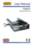
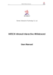
User Manual
www.doughty-engineering.co.uk
IWB
Internally Wired Bar
Version 12/10
www.doughty-engineering.co.uk
Purpose
Title
Purpose
To support and power items of equipment used within the entertainment industry (TV, Film,
and Theatre) such as specialist luminaires, fog machines, audio equipment etc.
Cautions
1. IWBs ARE FOR INDOOR USE ONLY
2. Fixings should only be made to a safe structure, using proprietary products and should
never be further than 2m apart.
3. This product should be installed by competent persons only, and in such a way as to
conform to any local regulations which may prevail.
4. The Safe Working Load must be adhered to: 39Kg per linear meter evenly distributed
or 19.5Kg point load, between any two fixing points at 2m spacing – grater loads are
acceptable with closer fixings, see BS 7906 – 1 for further information.
5. This product MUST be adequately earthed and the socket outlets must be protected with
a protective over current device, e.g. RCD, fuse, etc.
6. It is the responsibility of the installer to ensure the product and the cabling it is connected
to meets or exceeds the electrical safety standards which prevail in the territory in which
it is fitted.
7. The product should be installed/rigged in such a way as to ensure it is secure and not
likely to be a safety hazard.
8. Ensure no flammable items are placed close to or over the bar or any equipment rigged
from it; particular cautions should be exercised when using drapes.
9. Ensure the weight load is evenly distributed along the length of the IWB.
10.An inspection of the bar, associated rigging and electrical connections should be
regularly made by a suitably qualified person.
11.Maximum current rating must not be exceeded under any circumstance:
NUMBER OF OUTLETS
OVERALL MAXIMUM CURRENT
3
45Amps
4+
60Amps
See rating plate for further details.
12. Electrical phases not to be mixed on IWBs – Single Phase only - Do Not Cross Patch.
13. Caution should be exercised in relation to working at height, risk of electric shock and any other factors which may present a hazard.
14. Items connected to this equipment should be firmly secured by appropriately rated proprietary clamps and always protected by a secondary safety bond with a suitable safe working load.
15. Items should not be plugged or unplugged while the power is connected.
16. Disconnection of Mains power may take place remotely from the bar and may be via the buildings electrical infrastructure – ensure you know where this is, how it is operated
and that it can not be inadvertently re-connected while you are Rigging.
17. Ensure the rigging clamp is fully tightened to the IWB and the item being rigged.
18. Ensure that if extension leads are used from other bars these are on the same phase as
the IWB.
www.doughty-engineering.co.uk
Installation
Installation
1. Fixing type will depend upon building structure but should always be secure and
adequately specified to take the weight of the bar as well as any load to be placed on it,
consider allowing a safety factor. The safe working load of the bar will be dependent upon
its fixings and the structure they are attached to, if in doubt consult a structural engineer,
Doughty Engineering Ltd will not accept responsibility for ascertaining the safe working load
of its products that are dependant upon factors outside of its control.
2. Doughty Engineering Ltd recommends the bar is rigged using M12 threaded rod or quality
wire rope and associated fittings. Various primary fixing methods are available dependant
upon the structure being fitted to.
3. Ensure safety issues are observed and risk assessment/method statements are
undertaken. – KNOW THE RISKS
4. Fixings should be arranged to equally distribute the load along the bar and superstructure.
5. Lay the bar out to check fixing positions and orientation of sockets etc.
6. If the Bar is made in two sections, take care not to damage internal cable when securing
the joiner. Ensure the Joiner M6 earthing screw is tightened through the Bar Joiner and into
the tapped receiver in the adjoining Bar. This will serve to earth Bar Joiner and to locate the
adjoining Bar in the Bar Joiner. Ensure that both sections of bar are close together and that
the tube joiner is centered across the two bars, thus fixing to equal lengths of tube.
7. When drilling the cable entry point in the termination box, take care to ensure the electrical
components and cable insulation are not damaged by the hole-saw, hot swarf, etc.
8. Fixings should be between 1.5 and 2.0 meters apart, if necessary add additional fixings to
ensure compliance. See Figure 1 below.
9. Fit primary fixings to building structure in accordance with manufacturer’s instructions. If
using a chemical anchor ensures that it has fully cured before applying a load, ensure any
bolts or nuts are tightened to require torque setting.
10.Load test fixing points to ensure they are capable of taking the specified load - including
safety factor.
11.Attach threaded rod or Wire rope to primary fixing point, fit universal clamps or wire rope
hanging clamps as appropriate and tighten.
12.The bar should now be lifted into place and offered to the fixings, if possible temporarily tie
the bar off whilst fixings are fitted around the aluminium tubing.
13.Do not slide or twist bar through clamps as this may damage the finish.
14.If applicable bring the cable into the termination box via the hole and appropriate gland and
terminate in accordance with local wiring or electrical regulations, taking care to ensure the
bar is Earthed.
15.Perform appropriate Electrical and load Tests
Ensure Earth Bolt
Is Fully Tightened
Ino Adjoining Bar
EARTH
DO NOT
REMOVE
www.doughty-engineering.co.uk
www.doughty-engineering.co.uk
Service & Maintenance
Title
1. The bar should be inspected by appropriately qualified personnel for both electrical and
mechanical integrity at least once a year, more frequently if local regulations require.
2. Before a load test, all fixing fasteners should be checked to ensure they are free from
damage and are tight.
3. Load tests should be carried out under the constraints of any local regulations which
prevail, e.g. Lifting Operations and Lifting Equipment Regulations 1998 in the UK.
4. The bar should be kept dry and free from excessive dust build up – disconnect from
mains and clean with a dry cloth or brush – do not use water or solvents.
5. Sockets and covers should not be interfered with by unqualified personnel.
6. If the bar requires replacement parts or servicing please contact Doughty Engineering
Ltd for the details of an approved service agent.
7. If the IWB requires dismantling and folding (7 meters or greater) e.g. If re locating, ensure
any exposed cables are adequately protected.
www.doughty-engineering.co.uk
Fixings should be no further than 2m apart, this provides Max UDL = 39 Kg between any two
fixings Max point load = 19.5 Kg in any meter – see Cautions on Page 2.
Illustrations
www.doughty-engineering.co.uk
Declaration of Conformity
Title
Doughty Engineering Limited
CROW ARCH LANE, RINGWOOD, HANTS, BH24 1NZ. ENGLAND
Telephone: +44 (0) 1425 478961 Fax: +44 (0) 1425 474481
www.doughty-engineering.co.uk
email:[email protected]
EC DECLARATION OF CONFORMITY
Doughty Engineering Limited hereby certify that the equipment stated below has been designed to comply
with all relevant sections of the specifications referenced below and complies with all the applicable Essential
Requirements of the EC Directives and amendments and the National Laws and Regulations adopting these
Directives.
Description: Lighting Bar
Model/s: All Doughty Engineering IWB’s within the parameters shown in the table below
15a Outlets
1.5 to 12 metres 3 to 12 mains sockets With or Without Data Sockets Silver or Black
16a Outlets
1.5 to 12 metres 3 to 12 mains sockets With or Without Data Sockets Silver or Black
15a & 16a Outlets 1.5 to 12 metres 3 to 12 mains sockets With or Without Data Sockets Silver or Black
are in conformity with the provision of the following EC Directives:
2006/95EC: Low Voltage Directive - as implemented into English Law under Statutory Instrument
1994 No. 3260 - The Electrical (Safety) Regulations 1994.
Harmonised Standards applied:
BS EN 60059: Electric Current, Rated Current, Electrical equipment, Electrical power systems,
measuring instruments, electronically operated devices.
EN 69965: Audio, Video and similar electronic apparatus - Safety Requirements
BS EN 600659: Section 3 - Ratings.
National Technical Standards & Specifications applied:
BS EN ISO 9001:1994
Signed:
Date: 25-04-08
Name: Nigel Curtis
Position: Technical Director
Being the responsible person appointed by the manufacturer.
DEQ 083 Rev 4
Company Registration No. London 972614
Registered Office: Crow Arch Lane, Ringwood, Hants, BH24 1NZ
Directors: M.B.Lister. J.C.G. Chiverton. N.D. Curtis. S.C. Wright
www.doughty-engineering.co.uk
Contact
Doughty Engineering Ltd
Crow Arch Lane
Ringwood, Hampshire, BH24 1NZ
Tel: +44 (0) 1425 478961 Fax: +44 (0) 1425 474481
email: [email protected]
Web: www.doughty-engineering.co.uk
Note: Whilst every effort has been made to ensure that the information contained within this manual is correct,
Doughty Engineering does not accept any liability for errors or omissions. Specifications and technical data are
intended for guidance purposes only and may vary.
www.doughty-engineering.co.uk