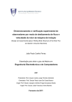
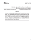
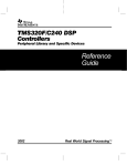
1
TECHNOSOFT RDIM16 Version 4.0 Resolver-to-digital Interface Module DSP Motion Solutions ACPM750E User Manual Technosoft 2001 TECHNOSOFT DSP Motion Solutions RDIM16 User Manual P091.080.UM.1001 October 2001 Technosoft S.A. Rue des Courtils 8A CH 2035 Corcelles Switzerland Tel: +(41) 32 732 5500 FAX: +(41) 32 732 5504 e-mail : [email protected] http://www. technosoft.ch RDIM16 v4.0 User Manual Contents Chapter 1. Introduction 2. Hardware overview 3. Installing and customizing RDIM16 4. Verifying RDIM16 Appendices Technosoft 2001 A. RDIM16 connectors and jumpers B. RDIM16 technical specifications C. Test program of the RDIM16 module D. RDIM16 - compatible DSP modules E. RDIM16 – mechanical drawings 1 RDIM16 v4.0 User Manual This page is empty Technosoft 2001 2 RDIM16 v4.0 User Manual Chapter 1. Introduction 1. Introduction The RDIM16 v4.0 is a resolver to digital interface module. It provides the resolver excitation and translates the returned angular analogue information into a digital form. The RDIM16 v4.0 is a plug-in module, which can be connected via the standard MC-BUS motion control bus with all the Technosoft products using the 5V MC-BUS or 3.3VMC-BUS. Hence, the RDIM16 module can be used together with: the MCK24xx Motion Control Kit, the IMMC24x Intelligent Modular Motion Controllers, the MSK24xx Motion Starter Kit, MCSK module, etc. thus offering an effective solution for motion control applications using motors with resolver feedback. The RDIM16 v4.0 module offers a complete solution for converting the analogue angular position provided by a resolver into a digital information, without the need for other components. The digital angular position output information is available on MC-BUS in 2 forms: • • as a serial binary output, providing the absolute position. This output is available on the serial peripheral interface (SPI) pins of the MC-BUS; The absolute position has 12 bits resolution providing 4096 values per rotation. The RDIM16 serial output can be enabled or disabled using the SPI control signal SPISTE. When disabled, the serial output is placed in the high-impedance state, allowing the exchange of the data with other serial devices connected on the same SPI bus. as 2 quadrature signals A and B, and a Z (zero) pulse, emulating an incremental encoder. These signals are available on the quadrature encoder interface pins of the MC-BUS; The encoder emulated outputs of the RDIM16 module continuously produce signals equivalent to a 1024-line encoder. If these outputs are used with an encoder interface, this multiplies by 4 the resolution, providing 4096 pulses per rotation. Key features • • • • • 12-bit serial absolute position 4x1024-lines incremental encoder emulation Differential inputs for resolver signals Internal 6.65-kHz oscillator providing sinusoidal excitation up to 7.5VRMS, 40mA 5V MC-BUS connectors allowing direct connection with Technosoft DSP boards for the TMS320F240 and TMS320F243 family • 3.3V MC-BUS connectors allowing direct connection with Technosoft DSP boards for the TMS320LF2407. • Do no request external power supply. Is powered via the MC-BUS connector Technosoft 2001 3 RDIM16 v4.0 User Manual Chapter 1. Introduction This page is empty Technosoft 2001 4 RDIM16 v4.0 User Manual Chapter 3. Hardware Overview 2. Hardware Overview Figure 2.1 presents the RDIM16 v4.0 block diagram. The interface module uses a step-up DC/DC converter to supply the reference generator unit which provides a constant amplitude sinusoidal excitation for a resolver. The differential sine and cosine signals generated by the resolver, pass through a signal conditioning unit and then are applied to a 12-bit resolver-to-digital converter1, which translates them into a digital information provided on the MC-BUS. Figure 2.1. The block diagram of the RDIM16 v4.0 interface board The resolver shall be connected to the RDIM16 v4.0 as following. Please read Chapter 3 to see how to adjust and set RDIM16 to match with your resolver. Resolver J5 Output connector 2 1 RR+ Off CC+ SW1 8 7 6 5 4 3 2 1 On S+ S- J6 Input connector 2 1 1 AD2S90, produced by Analog Devices Technosoft 2001 5 RDIM16 v4.0 User Manual Chapter 3. Hardware Overview RDIM16 v4.0 module connections Figure 2.2 presents a top view of the RDIM16 v4.0, which outlines the main components and the connectors. A short description of the connectors follows. Appendix A contains a complete description of all of the RDIM16 connectors. J3 M C-bus 3.3V connector J1 M C-Bus 5V connector 2 1 J5 Output connector Off SW1 J6 Input co nnector 8 7 6 5 4 3 2 1 On 2 1 2 1 J2 M C-Bus 5V connector Components side Solder side This drawing is not to scale Figure 2.2. The RDIM16 v4.0 board layout - Connectors Technosoft 2001 6 RDIM16 v4.0 User Manual Chapter 3. Hardware Overview MC-BUS connectors (J1, J2 and J3) Through the MC-BUS connectors, the RDIM16 board gets the +5VDC power supply and sends the digital angular information. When connected with the Technosoft DSP boards for the TMS320F24xx family, the digital angular information is passed to the MSK24xx DSP motion controller. Output connector (J5) Through J5 connector, the RDIM16 sends a constant amplitude sinusoidal excitation to the resolver. Input connector (J6) Through J6 connector, the RDIM16 gets the differential sine and cosine signals generated by the resolver. Technosoft 2001 7 RDIM16 v4.0 User Manual Chapter 3. Hardware Overview This page is empty Technosoft 2001 8 RDIM16 v4.0 User Manual Chapter 3. Installing and customizing RDIM16 3. Installing and customizing RDIM16 3.1. Installing RDIM16 module The RDIM16 v4.0 resolver to digital interface was designed as a module which can be plugged-in Technosoft DSP boards for the TMS320F24xx family (see Appendix D for the list of these modules), using the MC-BUS connectors for data exchange. In order to allow an easy mounting, and at the same time to leave open the possibility to add further modules on the MC-BUS, the RDIM16 board is delivered with standard 2 x 18 (0.1”) PC-104 connectors already mounted. Hence the board installation simply resumes to plug the RDIM16 module in the mother device (MSK240, MSK243, MSK2407, IMMC24x, MCSK, etc.) with J1, J2 connectors aligned (RDIM’s J1 to mother device’s J1 and RDIM’s J2 to mother device’s J2). If the mother device is not equipped with connectors, Technosoft will deliver them on request. DSP board Using RDIM16v4.0 and DSP boards with: TMS320F240 TMS320F243 MotionChip Using RDIM16v4.0 and DSP boards with: TMS320F2407 Position in stack first upper board last bottom board first upper board Boards assembly order PM50v2.0 ACPM750E v3.2 & v3.3 Any order Interconnection only through J1 and J2 connectors Any order Interconnection only through J1 and J2 connectors PM50v3.0 RDIM16v4.0(J1,J2) MCK240 (J1, J2) PM50v30 (J1, J2) MSK2407 (J3) MSK2407 (J3) RDIM16v4.0 (J3) RDIM16v4.0 (J3) MSK2407 (J3) LF2407 Adapter (Note1) LF2407 Adapter (Note2) RDIM16v4.0 (J3) PM50v30 (J3) last bottom PM50v20 (J1, J2) ACPM750 (J1, J2) board Note 1: For use LF2407 adapter with PM50v20 – all jumpers on LF2407 Adapter must be on 1-2 position. Note 2: For use LF2407 adapter with ACPM750 – all jumpers on LF2407 Adapter must be on 2-3 position. Note 3: Always, J1and J2 are used for 5V level signals, and J3 for 3.3V level signals. Technosoft 2001 9 RDIM16 v4.0 User Manual Chapter 3. Installing and customizing RDIM16 3.2. Customizing RDIM16 for your resolver In order to connect your resolver to the RDIM16 resolver to digital interface you first need to configure the board to match with your resolver basic data. CAUTION Do not connect your resolver without reading this information. If RDIM16 interface module is not properly configured, your resolver will be damaged! In most of the cases, the resolver basic data mean: • IIN - resolver input current for a given UIN - input voltage (RMS) and a given fIN - frequency; • UOUT - output voltage (RMS) or transformation ratio = UIN/UOUT; • RR - resolver resistance; Normally, the UIN input voltage at which the IIN input current is given represents the optimum value at which the excitation should be provided. The RDIM16v4.0 provides a 6.65 kHz sinusoidal excitation signal with constant amplitude. The excitation can be selected between 0.5 and 7.5VRMS. The 6.65 kHz excitation frequency is fixed and can not be adjusted. The excitation current can be up to 40mA. The resolver feedback voltage should be in the range 0.5 to 8 VRMS. 3.2.1. Computing the equivalent resolver input voltage at 6.65 kHz If your resolver input current is provided at 6.65 kHz go to next paragraph. If the frequency differs, you must estimate which is the equivalent input voltage at 6.65 kHz - UINE , you need, in order to supply the resolver with the same current IIN . This can be computed based on the resolver resistance RR and inductance LR. If the inductance is not given, it can be computed with formula: LR = U 2IN − R 2R ⋅ I 2IN I IN ⋅ 2 ⋅ π ⋅ f IN Where: IIN input current is in Amps, UIN input voltage in Volts, fIN input frequency is in Hz, RR resolver resistance is in ohms and the resolver inductance LR results in Henry Now you can estimate the equivalent input voltage for 6.65 kHz with formula: U INE = U IN ⋅ R 2R + L2R ⋅ ω 2RDIM R 2R + L2R ⋅ ω 2IN Where: ω IN = 2 ⋅ π ⋅ f IN , UIN input voltage in Volts, fIN input frequency is in Hz, RR resolver resistance is in ohms, LR resolver inductance is in Henry and the equivalent input voltage UINE results in Volts. Technosoft 2001 10 RDIM16 v4.0 User Manual Chapter 3. Installing and customizing RDIM16 3.2.2. Adjusting RDIM16 output stage amplification 2 1 Off SW1 8 7 6 5 4 3 2 1 On 2 1 2 1 Figure 2.3. The RDIM16 v4.0 board layout - Jumpers Once the equivalent input voltage is determined, you need to tune the RDIM16 output stage amplification to provide an excitation signal with RMS value equal with the UINE computed above. The excitation voltage level can be modified from potentiometer VR1 and jumper JP2 (see Figure 2.3). Do the following steps: 1. Remove jumper JP2 and turn to the end potentiometer VR1 in the CCW direction. In this configuration the excitation amplitude will be minimal with the resolver connected; 2. Mount the RDIM module into the mother device and connect the resolver excitation input to RDIM’s J5 connector with REF+ on pin 3, REF- on pin 1 and cable shield on pin 2 (see Appendix A); 3. Turn on the power supply; 4. Use a true RMS voltmeter to measure the excitation RMS value between pins 1 and 3; 5. Turn CW the potentiometer VR1 until the UINE value is reached; 6. If the potentiometer reaches the CW limit and excitation voltage is still under the desired value, turn back the potentiometer until the CCW limit is reached and put jumper JP2. Then turn once again CW the potentiometer VR1 until the UINE value is reached. 3.2.3 Adjusting RDIM16 input stage amplification Finally, you need to adjust the RDIM16 input stage in order to translate the resolver output voltage into the voltage range accepted by the resolver-to-digital converter, which is 2VRMS ± 0.1V. First, compute your resolver estimated output voltage UOUTE that results when the equivalent input voltage UINE is applied, with the formula: UOUTE = UINE ⋅ transformation ratio = UINE ⋅ UIN/UOUT Technosoft 2001 11 RDIM16 v4.0 User Manual Chapter 3. Installing and customizing RDIM16 Then configure SW1 (see Figure 2.3) according to Table 3.1. For intermediate values always choose the SW1 combination corresponding to the nearest lower voltage: VSET. For example if UOUTE = 1.8V, select the SW1 combination corresponding to VSET = 1.5V. Then, do the following steps: 1. Turn off the power supply; 2. Connect the resolver differential outputs to RDIM16’s JP6 connector with: COS+ on pin 2, COS- on pin 1, SIN+ on pin 4, SIN- on pin 5 and cable shield on pin 3 (see Appendix A); 3. Turn on the power supply; 4. Use a true RMS voltmeter to measure the resolver output value between J6 connector pins 1 and 2 or between pins 4 and 5; 5. Manually rotate your resolver (or the motor on which it is fixed) until you get the maximum voltage; 6. Turn slightly the VR1 potentiometer in the CCW/CW direction to decrease/increase the resolver output voltage until it becomes equal with VSET - the value corresponding to the selected SW1 combination. Table 3.1. SW1 configuration for different resolver output voltages Resolver output RMS voltage measured between JP6 pins 1 and 2 (or 4 and 5) 1 off on off on off on off on off on off on off on off on 0.5 V 1.0 V 1.5 V 2.0 V 2.5 V 3.0 V 3.5 V 4.0 V 4.5 V 5.0 V 5.5 V 6.0 V 6.5 V 7.0 V 7.5 V 8.0 V Technosoft 2001 SW1 configuration 12 2 off off on on off off on on off off on on off off on on 3 off off off off on on on on off off off off on on on on 4 off off off off off off off off on on on on on on on on 5 off on off on off on off on off on off on off on off on 6 off off on on off off on on off off on on off off on on 7 off off off off on on on on off off off off on on on on 8 off off off off off off off off on on on on on on on on RDIM16 v4.0 User Manual Chapter 4. Verifying RDIM16 4. Verifying RDIM16 After you have customized the RDIM16 for your resolver, you can verify how the interface module works. There are two interfaces of the RDIM16 module, which must be checked: 1. The SPI communication channel, allowing you to read the absolute position information from the RDIM16 module to the DSP one. 2. The QEP quadrature encoder interface, allowing you to read the encoder-like signals generated by the RDIM16 module towards the DSP module The RDIM16 package includes a demo floppy disk with a ready-to-run example presenting how to read the absolute position using the serial SPI interface, when RDIM16 is used together with one of the Technosoft DSP boards for the TMS320F24xx family. Source code of the demo program is included too. Use the communication monitor from your DSP board software package, to download the RDIM16 test program TSRDIM40.OUT for TMS320F240 based DSP boards, TSRDIM43.OUT for TMS320F243-based DSP boards, TSRDIM07.OUT for TMS320F243-based DSP boards with monitor command ‘l tsrdim40.out’ (respectively 'l tsrdim43.out' or 'l tsrdim07.out'). Then start it’s execution from the address 0x8000 with monitor command ‘r 8000’ and inspect memory location 0x200 with monitor command ‘i 200’. The value displayed represents the absolute position in the range 0 to 4096, read from the resolver through the SPI interface. If you turn manually the resolver you should see how the displayed position value is changing. A second test can be done using the Processor Evaluation program PROCEV, also included in the software packages accompanying Technosoft DSP boards for the TMS320F24xx family. Open the QEP (Quadrature Encoder Pulse) test. This test computes and displays graphically the relative position provided by the 2-quadrature signals A and B of an encoder. When the RDIM16 board is connected to the system, A and B signals are generated by the RDIM16, emulating an incremental encoder. Run the test and start turning manually the resolver. You should see how the relative position read through the quadrature encoder interface is changing. Technosoft 2001 13 RDIM16 v4.0 User Manual Chapter 4. Verifying RDIM16 This page is empty Technosoft 2001 14 RDIM16 v4.0 User Manual Appendix A. RDIM16 Connectors an Jumpers Appendix A. RDIM16 Connectors A.1. Connectors J1 MC-BUS 5V Connector - signals on 'F240-based DSP boards Pin # MC-BUS Signal RDIM16 Signal Pin # MC-BUS Signal RDIM16 Signal 1 3 5 7 9 11 13 15 17 19 21 23 25 27 29 31 33 35 n.c. PWM1 PWM3 PWM5 CMP7 / IOPB0 CMP9 / IOPB2 T2CMP / IOPB4 TMRDIR / IOPB6 QEP1 / IOPC4 CAP3 / IOPC6 PDPINT SCIRXD / IO +5VDC DGND DGND ADCIN5 ADCIN6 ADCIN7 n.c. n.c. n.c. n.c. n.c. n.c. n.c. n.c. encoder A (Dig. O) encoder Z (Dig. O) n.c. n.c. 5V Supply Input Power ground Analog ground n.c. n.c. n.c. 2 4 6 8 10 12 14 16 18 20 22 24 26 28 30 32 34 36 n.c. PWM2 PWM4 PWM6 CMP8 / IOPB1 T1CMP / IOPB3 T3CMP / IOPB5 TMRCLK / IOPB7 QEP2 / IOPC5 CAP4 / IOPC7 XINT2 / IO SCITXD / IO DGND DGND VrefLO ADCIN13 ADCIN14 ADCIN15 n.c. n.c. n.c. n.c. n.c. n.c. n.c. n.c. encoder B (Dig. O) n.c. n.c. n.c. Digital Ground Power ground n.c. n.c. n.c. n.c. Technosoft 2001 15 RDIM16 v4.0 User Manual Appendix A. RDIM16 Connectors an Jumpers J2 MC-BUS 5V Connector - signals on 'F240-based DSP boards Pin # 1 3 5 7 9 11 13 15 17 19 21 23 25 27 29 31 33 35 MC-BUS Signal RDIM16 Signal ADCIN2 n.c. ADCIN3 n.c. ADCIN4 n.c. VrefLO n.c. DGND Analog ground IOPA0 n.c. IOPA1 n.c. DGND Analog ground RX n.c. n.c. n.c. +5VDC 5V Supply Input PORESET n.c. n.c. n.c. SPISIMO / IO n.c. SPICLK / IO RDIM16 SPICLK (Dig. I) ADCSOC / IOPC0 n.c. XF / IOPC2 n.c. XINT3 / IO n.c. Pin # MC-BUS Signal RDIM16 Signal 2 4 6 8 10 12 14 16 18 20 22 24 26 28 30 32 34 36 ADCIN10 ADCIN11 ADCIN12 VrefHI DGND IOPA3 IOPA2 DGND TX n.c. +5VDC n.c. n.c. SPISOMI / IO SPISTE / IO CLKOUT / IOPC1 BIO / IOPC3 NMI n.c. n.c. n.c. n.c. Analog ground n.c. n.c. Digital Ground n.c. n.c. 5V Supply Input n.c. n.c. DATA OUT (Dig. O) SPI ENABLE (Dig. I) n.c. n.c. n.c. Notes: a) “I” - input; “O” - output; “Dig.” - Digital; “Anlg.” - Analog; “n.c.” - not connected b) Encoder emulated signals A,B,Z are always active. c) DATA OUT is in HighZ if SPI ENABLE is set high (1 logic) Technosoft 2001 16 RDIM16 v4.0 User Manual Appendix A. RDIM16 Connectors an Jumpers J1 MC-BUS Connector - signals on 'F243-based DSP boards Pin # MC-BUS Signal RDIM16 Signal Pin # MC-BUS Signal RDIM16 Signal 1 3 5 7 9 11 13 15 17 19 21 23 25 27 29 31 33 35 - n.c. PWM1 PWM3 PWM5 IOPD2 IOPD4 T2CMP / IOPB5 TMRDIR / IOPB6 QEP1 / IOPA3 CAP3 / IOPA5 #PDPINT SCIRXD / IOPA1 +5VDC DGND DGND - n.c. - (ADCIN4) ADCIN0 ADCIN2 n.c. n.c. n.c. n.c. n.c. n.c. n.c. n.c. encoder A (Dig. O) encoder Z Dig. O) n.c. n.c. 5V Supply Input Power ground Analog ground n.c. n.c. n.c. 2 4 6 8 10 12 14 16 18 20 22 24 26 28 30 32 34 36 - n.c. PWM2 PWM4 PWM6 IOPD3 T1CMP / IOPB4 IOPD5 TMRCLK / IOPB7 QEP2 / IOPA4 IOPD6 XINT2 / IOPD1 SCITXD / IOPA0 DGND DGND VrefLO - n.c. ADCIN1 ADCIN3 n.c. n.c. n.c. n.c. n.c. n.c. n.c. n.c. encoder B (Dig. O) n.c. n.c. n.c. Digital Ground Power ground n.c. n.c. n.c. n.c. J2 MC-BUS Connector - signals on 'F243-based DSP boards Pin # 1 3 5 7 9 11 13 15 17 19 21 23 25 27 29 31 33 MC-BUS Signal RDIM16 Signal - n.c. n.c. ADCIN4 n.c. ADCIN6 n.c. VrefLO n.c. DGND Analog ground - n.c. n.c. - n.c. n.c. DGND Analog ground RxD n.c. CAN_HI n.c. +5VDC 5V Supply Input #RESET n.c. CAN_LO n.c. SPISIMO / IOPC2 n.c. SPICLK / IOPC4 RDIM16 SPICLK (Dig. I) IOPD7 n.c. XF / IOPC0 n.c. Technosoft 2001 17 Pin # MC-BUS Signal RDIM16 Signal 2 4 6 8 10 12 14 16 18 20 22 24 26 28 30 32 34 - n.c. ADCIN5 ADCIN7 VrefHI DGND - n.c. - n.c. DGND TxD CAN_VCC +5VDC --CAN_GND SPISOMI / IOPC3 SPISTE / IOPC5 CLKOUT / IOPD0 BIO / IOPC1 n.c. n.c. n.c. n.c. Analog ground n.c. n.c. Digital Ground n.c. n.c. 5V Supply Input n.c. n.c. DATA OUT (Dig. O) SPI ENABLE (Dig. I) n.c. n.c. RDIM16 v4.0 User Manual Appendix A. RDIM16 Connectors an Jumpers Pin # MC-BUS Signal RDIM16 Signal Pin # MC-BUS Signal RDIM16 Signal 35 XINT1 / IOPA2 n.c. 36 #NMI n.c. Technosoft 2001 18 RDIM16 v4.0 User Manual Appendix A. RDIM16 Connectors an Jumpers J3 MC-BUS 3.3V Connector - signals for 'F2407 boards Pin # MC-BUS Signal RDIM16 Signal Pin # MC-BUS Signal RDIM16 Signal 1 3 5 7 9 +3.3V PWM1 / IOPA6 PWM3 / IOPB0 PWM5 / IOPB2 T1PWM / T1CMP / IOPB4 TDIRA / IOPB6 CAP1 / QEP1 / IOPA3 CAP3 / IOPA5 XINT2 / ADCSOC / IOPD0 SPISIMO / IOPC2 SPICLK / IOPC4 GND +5V VREFHI ADCIN00 ADCIN02 ADCIN04 ADCIN06 n.c. n.c. n.c. n.c. n.c. 2 4 6 8 10 n.c. n.c. n.c. n.c. n.c. n.c. encoder A (Dig. O) 12 14 encoder Z Dig. O) n.c. 16 18 +3.3V PWM2 / IOPA7 PWM4 / IOPB1 PWM6 / IOPB3 T2PWM / T2CMP / IOPB5 TCLKINA / IOPB7 CAP2 / QEP2 / IOPA4 #PDPINTA #BIO / IOPC1 n.c. SPICLK (Dig. I) GND +5V n.c. n.c. n.c. n.c. n.c. 20 22 24 26 28 30 32 34 36 SPISOMI_J3 SPISTE_J3 GND +5V VREFLO ADCIN01 ADCIN03 ADCIN05 ADCIN07 11 13 15 17 19 21 23 25 27 29 31 33 35 n.c. encoder B (Dig. O) n.c. n.c. DATA OUT (Dig. O) SPI ENABLE (Dig. I) GND +5V n.c. n.c. n.c. n.c. n.c. J5 RDIM16 Output Connector Pin # Signal Description 1 2 3 RSHIELD R+ Reference/Excitation Signal Return Cable Shield Reference/Excitation Signal J6 RDIM16 Input Connector Pin # Signal Description 1 2 3 4 5 CC+ SHIELD S+ S- COSLO Differential Input COS Differential Input Cable Shield SIN Differential Input SINLO Differential Input Technosoft 2001 19 RDIM16 v4.0 User Manual Appendix A. RDIM16 Connectors an Jumpers A.2. Jumpers JP1 Jumper (located on component side; use 0 Ohm link soldering) Configuration Description open emulated Z is 90° wide and starts on positive transition of A signal when angle is increasing - factory default 1-2 emulated Z is 180° wide and starts on positive transition of A signal when angle is increasing 2-3 emulated Z is 360° wide and starts on positive transition of A signal when angle is increasing JP2 Jumper Configuration open closed Description output (excitation) voltage is in lower half range output (excitation) voltage is in higher half range JP3 Jumper Configuration open closed Technosoft 2001 Description - used to select the RDIM16 from 24x DSP modules that do have also E2ROM memory, connected on the SPI interface - used for MSK2407 with JP10 in position 2-3 (share selection signals with E2ROM). See MCK2407 User Manual - used to select the RDIM from 24x DSP modules that do not have E2ROM memory, connected on the SPI interface - used for MSK2407 with jumper between JP10/3 and JP11/ 2 (without using on board E2ROM). See MCK2407 User Manual 20 RDIM16 v4.0 User Manual Appendix A. RDIM16 Connectors an Jumpers SW1 Dip Switch Resolver output RMS voltage measured between JP6 pins 1 and 2 (or 4 and 5) SW1 configuration 1 off on off on off on off on off on off on off on off on 0.5 V 1.0 V 1.5 V 2.0 V 2.5 V 3.0 V 3.5 V 4.0 V 4.5 V 5.0 V 5.5 V 6.0 V 6.5 V 7.0 V 7.5 V 8.0 V Technosoft 2001 21 2 off off on on off off on on off off on on off off on on 3 off off off off on on on on off off off off on on on on 4 off off off off off off off off on on on on on on on on 5 off on off on off on off on off on off on off on off on 6 off off on on off off on on off off on on off off on on 7 off off off off on on on on off off off off on on on on 8 off off off off off off off off on on on on on on on on RDIM16 v4.0 User Manual Appendix B. RDIM16 Technical Specifications Appendix B. RDIM16 - Hardware Technical Specifications Parameter Value Reference/excitation Output current Output voltage Frequency max. 40mARMS 0.5 – 7.5VRMS 6.65 KHz, fixed Feedback Impedance 6KΩ 0.5 - 8VRMS Input voltage Resolution 12 bits / revolution Power Supply 5V±5% max. 110mA Current consumption Angular Resolution of the RDIM16 module is 12 Bits. Technosoft 2001 22 RDIM16 v4.0 User Manual Appendix B. RDIM16 Technical Specifications This page is empty Technosoft 2001 23 RDIM16 v4.0 User Manual Appendix C. Test Program of the RDIM16 module Appendix C. Test program of the RDIM16 module The following programs may be used to perform a test of the RDIM16 module. The programs initialize the SPI interface of the TMS320F24xx DSP controller, and read the resolver output via the SPI interface. The read value is stored into a data memory location, and may be used consequently. The program continuously reads this value and communicates via the RS-232 interface (SCI), through the communication monitor, with the PC computer. Thus, the user may visualize on-line the value read from the resolver. The listings of two types of files are presented (asm and cmd): - C1 - the “TSRDIM40.asm” file for the TMS320F240-based DSP boards, containing the assembler source file of this example - C2 - the “TSRDIM40.cmd” file for the TMS320F240-based DSP boards, , containing the command file for the linker program - C3 - the “TSRDIM43.asm” file for the TMS320F243-based DSP boards, containing the assembler source file of this example - C4 - the “TSRDIM43.cmd” file for the TMS320F243-based DSP boards, containing the command file for the linker program - C5 - the “TSRDIM07.asm” file for the TMS320F2407-based DSP boards, containing the assembler source file of this example - C6 - the “TSRDIM07.cmd” file for the TMS320F2407-based DSP boards, containing the command file for the linker program Technosoft 2001 24 RDIM16 v4.0 User Manual Appendix C. Test Program of the RDIM16 module C.1. TSRDIM40.asm source file for TMS320F240 - based DSP modules ;---------------------------------------------------------------------; File Name: rdim.asm ; Project: MCK240 ; Originator: I. Stefan ; Description: ASM file for RDIM demo ; Copyright © 1998 Technosoft ;---------------------------------------------------------------------; Serial Peripheral Interface (SPI) Registers ;---------------------------------------------------------------------SPI_CNTL1 .set 07040h ; SPI Config Control Register 1 SPI_CNTL2 .set 07041h ; SPI Operation Control Register 2 SPI_STATUS .set 07042h ; SPI Status Register SPI_BAUD .set 07044h ; SPI Baud Rate Control Register SPI_BUF .set 07047h ; SPI Serial Input buffer reg SPI_DAT .set 07049h ; SPI Serial Data Register SPI_PORT_C1 .set 0704Dh ; SPI Port Control Register 1 SPI_PORT_C2 .set 0704Eh ; SPI Port control Register 2 ;---------------------------------------------------------------------; Constant defines ;----------------------------------------------------------------------MON240 .set 0109h ; monitor's command interpreter SPICCR .set 8007h ; SPI Configuration Control Register ; clk polarity low, 8 bits character length ; SPI software reset SPICTL .set 0006h ; SPI Operation Control Register ; disable receive error interrupt, disable SPI interr. ; enable transmitter, normal clocking, SPI master SPIPC1 .set 0052h ; SPI Port Control Register 1 ; SPISTE configured as output pin ; SPICLK pin contains SPI clock SPIPC2 .set 0022h ; SPI Port Control Register 2 ; SPISIMO and SPISOMI contains SPI data SPIBAUD .set 0013h ; SPI Baud Register, 500kBaud ; with 10 MHz SYSCLK ;---------------------------------------------------------------------; Bit Codes for Test Bit Instruction (BIT) ;---------------------------------------------------------------------BIT6 .set 0009h ; Bit Code for 6 ;---------------------------------------------------------------------; Bit masks to reset a bit with AND ;---------------------------------------------------------------------RSTB7 .set 0FF7Fh ; Bit Mask for 7 RSTB6 .set 0FFBFh ; Bit Mask for 6 ;---------------------------------------------------------------------; Bit masks to set a bit with OR ;---------------------------------------------------------------------SETB6 .set 0040h ; Bit Mask for 6 ;---------------------------------------------------------------------; M A C R O - Definitions ;----------------------------------------------------------------------RESBIT .macro DMA, MASK ;Clear bit Macro LACL DMA AND #MASK SACL DMA Technosoft 2001 25 RDIM16 v4.0 User Manual Appendix C. Test Program of the RDIM16 module .endm ;----------------------------------------------------------------------SETBIT .macro DMA, MASK ;Set bit Macro LACL DMA OR #MASK SACL DMA .endm ;----------------------------------------------------------------------; Global Variables ;----------------------------------------------------------------------.global _read_char .global _rdim_pos .global START ;----------------------------------------------------------------------; Global variables space reservation ;----------------------------------------------------------------------_rdim_pos .usect "MCK_1",1 _read_char .usect "MCK_1",1 _aux .usect "MCK_1",1 ;----------------------------------------------------------------------; Global Functions: ;----------------------------------------------------------------------.global _InitSPI .global _ReadSPIbuf .global _ReadRDIM .global _Delay ;----------------------------------------------------------------------; M A I N C O D E - starts here ;----------------------------------------------------------------------.text ;----------------------------------------------------------------------START: CALL _InitSPI Loop: CALL _ReadRDIM CALL MON240 B Loop ;----------------------------------------------------------------------; M A I N C O D E - ends here ;----------------------------------------------------------------------; S u b r o u t i n e s ;----------------------------------------------------------------------_InitSPI: ;----------------------------------------------------------------------LDP #0E0h SPLK #SPICCR, SPI_CNTL1 ; SPI Configuration Control Register SPLK #SPICTL, SPI_CNTL2 ; SPI Operation Control Register SPLK #SPIBAUD, SPI_BAUD ; SPI Baud Register SPLK #SPIPC1, SPI_PORT_C1 ; SPI Port Control Register 1 SPLK #SPIPC2, SPI_PORT_C2 ; SPI Port Control Register 2 RESBIT SPI_CNTL1, RSTB7 ; wake-up SPI from reset ; RET ;----------------------------------------------------------------------_ReadSPIbuf: ;----------------------------------------------------------------------Wait: LDP #0E0h Technosoft 2001 26 RDIM16 v4.0 User Manual Appendix C. Test Program of the RDIM16 module BIT BCND SPI_STATUS, BIT6 Wait,NTC ; test SPI INT FLAG ; wait to finish transmitting/receiving data LACL AND LDP SACL SPI_BUF #00FFh #_read_char _read_char ; load ACCL with received character ; mask unsignificant bits in ACC ; ; store SPI received character in memory ; RET ;----------------------------------------------------------------------_ReadRDIM: ;----------------------------------------------------------------------LDP #0E0h RESBIT SPI_PORT_C1, RSTB6 ; transmit "0" logic to select RDIM CALL _Delay SPLK #0ffh, SPI_DAT CALL _ReadSPIbuf ; read first character received via SPI SFL LDP #_aux SACL _aux,7 ; store rec. character shifted by 8 bits LDP #0E0h SPLK #0ffh, SPI_DAT CALL _ReadSPIbuf ; read second character received via SPI ; LDP #_aux OR _aux ; compose the word AND #7FFFh ; mask the first bit CLRC SXM RPT #2h SFR ; shift right with 3 bits to get position on 12bits ; LDP #_rdim_pos SACL _rdim_pos ; store position LDP #0E0h SETBIT SPI_PORT_C1, SETB6; transmit "1" logic to disable RDIM CALL _Delay ; necessary in case of continuously read from RDIM ; RET ;----------------------------------------------------------------------_Delay: ;----------------------------------------------------------------------RPT #10h NOP ; RET ;----------------------------------------------------------------------- Technosoft 2001 27 RDIM16 v4.0 User Manual Appendix C. Test Program of the RDIM16 module C.2. TSRDIM40.cmd linker command file /*-------------------------------------------------------------------*/ /* LINKER COMMAND FILE - MEMORY SPECIFICATION for C240 */ /*-------------------------------------------------------------------*/ /* LINKER DIRECTIVES */ /*-------------------------------------------------------------------*/ -e START /* Define Start Point*/ -l rts2xx.lib /* RUN-TIME SUPPORT - STACK MODEL */ -o testrdim.out -m testrdim.map /*-------------------------------------------------------------------*/ /* MEMORY ALLOCATION */ /*-------------------------------------------------------------------*/ MEMORY { PAGE 0: FLASH : origin = 0, length = 0x4000 /* on-chip Flash */ PM_F : origin = 0x8000,length = 0x3500 /* ext. PM free */ B0PM_F : origin = 0xfe00, length = 0x100 /* B0 PM free */ PAGE 1: REGS INTVEC BMCK1 M_VARS SPS AP_VAR LOG REF SPS1 : origin = 0, length = 0x60 /* mem.-mapped regs. */ : origin = 0x60,length = 0x20 /* DMB2 with int.vect*/ : origin = 0200h, length = 0x80 /* DARAM */ : origin = 0x280,length = 0x100 /* monitor used DM */ : origin = 0x380, length = 0x80 /* monitor stack */ : origin = 0xB500, length = 0x1000 /* appl. vars. */ : origin = 0xC500, length = 0x2000 /* logger DM */ : origin = 0xE500, length = 0x200 /* free ext.DM */ : origin = 0xE700, length = 0x300 /* free ext.DM */ } SECTIONS { .text: .cinit: .switch: .const: .data: .sysmem .bss: mvar: MCK_1: LOGGER: REFER: .stack: } { { { { { { { { } } } } } } } } > > > > > > > > { } { } { } { } Technosoft 2001 PM_F PAGE 0 PM_F PAGE 0 PM_F PAGE 0 PM_F PAGE 0 PM_F PAGE 0 M_VARS PAGE 1 AP_VAR PAGE 1 AP_VAR PAGE 1 > BMCK1 PAGE 1 > LOG PAGE 1 > REF PAGE 1 > SPS1 PAGE 1 28 RDIM16 v4.0 User Manual Appendix C. Test Program of the RDIM16 module C.3. TSRDIM43.asm source file for TMS320F243 - based DSP modules ;----------------------------------------------------------------------; File Name: TsRDIM43.asm ; Project: MCK243 ; Originator: I. Stefan ; Description: ASM file for RDIM demo ; Copyright © 1999 Technosoft ;----------------------------------------------------------------------; Constant defines ;----------------------------------------------------------------------; Serial Peripheral Interface (SPI) Registers ;----------------------------------------------------------------------SPI_CNTL1 .set 07040h ; SPI Config Control Register 1 SPI_CNTL2 .set 07041h ; SPI Operation Control Register 2 SPI_STATUS .set 07042h ; SPI Status Register SPI_BAUD .set 07044h ; SPI Baud Rate Control Register SPI_RX_BUF .set 07047h ; SPI Serial receive buffer reg SPI_DAT .set 07049h ; SPI Serial Data Register ;----------------------------------------------------------------------; Digital I/O ;----------------------------------------------------------------------OCRB .set 07092h ; I/O Mux. Control Register B ;----------------------------------------------------------------------; Data Page Pointer Definitions ;----------------------------------------------------------------------DP_PF1 .set 0E0h ; Data Page for Peripheral File 1 (7000h-7080h) DP_PF2 .set 0E1h ; Data Page for Peripheral File 2 (7080h-7100h) ;----------------------------------------------------------------------; Bit Codes for Test Bit Instruction (BIT) ;----------------------------------------------------------------------BIT6 .set 0009h ; Bit Code for 6 ;----------------------------------------------------------------------; Bit masks to reset a bit with AND ;----------------------------------------------------------------------RSTB7 .set 0FF7Fh ; Bit Mask for 7 ;----------------------------------------------------------------------; Bit masks to set a bit with OR ;----------------------------------------------------------------------SETB7 .set 0080h ; Bit Mask for 7 ;----------------------------------------------------------------------MON243 .set 0e3h ; monitor's command interpreter SPICCR .set 004Fh ; SPI Configuration Control Register ; clk polarity high, 16 bits character length SPICTL .set 0006h ; SPI Operation Control Register ; disable receive error interrupt, disable SPI interrupt ; enable transmitter, normal clocking, SPI master SPISEL .set 003Ch ; configure the shared I/O pins as SPI pins ; SPISIMO(OCRB.2), SPISOMI(OCRB.3), SPICLK(OCRB.4) and SPISTE(OCRB.5) ; SPISIMO - output pin, SPISOMI - input pin SPIBAUD .set 0009h ; SPI Baud Register 1MHz with CLKOUT = 20 MHz ;----------------------------------------------------------------------; M A C R O - Definitions ;----------------------------------------------------------------------- Technosoft 2001 29 RDIM16 v4.0 User Manual Appendix C. Test Program of the RDIM16 module RESBIT .macro DMA, MASK ;Clear bit Macro LACL AND SACL DMA #MASK DMA .endm ;----------------------------------------------------------------------SETBIT .macro DMA, MASK ;Set bit Macro LACL DMA OR #MASK SACL DMA .endm ;----------------------------------------------------------------------; Global Variables ;----------------------------------------------------------------------.global START .global _RDIM_Value ;----------------------------------------------------------------------; Global variables space reservation ;----------------------------------------------------------------------_RDIM_Value .usect "MCK_1",1 ;----------------------------------------------------------------------; Global Functions: ;----------------------------------------------------------------------.global ReadRDIM ;----------------------------------------------------------------------; M A I N C O D E - starts here ;----------------------------------------------------------------------.text ;----------------------------------------------------------------------START: ; reset SPI LDP #DP_PF1 RESBIT SPI_CNTL1, RSTB7 ; software reset SPI ; init SPI LDP LACL OR SACL #DP_PF2 ; Output Control Register Data Page #SPISEL ; pin functions ; Output Control Register OCRB OCRB LDP #DP_PF1 ; SPI Control Registers Data Page SPLK #SPICCR, SPI_CNTL1 ; SPI Comunication Control Register SPLK #SPICTL, SPI_CNTL2 ; SPI Operation Control Register SPLK #SPIBAUD, SPI_BAUD ; SPI Baud Register ; wake-up SPI from reset SETBIT SPI_CNTL1,SETB7 ; loop: ; call monitor CALL MON243 CALL ReadRDIM B loop ;----------------------------------------------------------------------; M A I N C O D E - stop here ;----------------------------------------------------------------------; S u b r o u t i n e s ;----------------------------------------------------------------------ReadRDIM: Technosoft 2001 30 RDIM16 v4.0 User Manual Appendix C. Test Program of the RDIM16 module LDP SPLK #0E0h #0h, SPI_DAT ; load data page ; SPI_DAT = FFFFh WaitToReadValue: LDP #DP_PF1 BIT SPI_STATUS, BIT6 BCND WaitToReadValue, NTC LACL CLRC RPT SFR LDP SACL RET ; read the word recceived via SPI ; test SPI INT FLAG ; if FLAG NEQ 1, loop back on output SPI_RX_BUF ;else,load ACCL with rcv.word,thus reset SPI flag SXM ; clear sign extention mode #3h ; repeat ; shift right with 4 bits to obtain position on 12bits #_RDIM_Value _RDIM_Value ; save the read value Technosoft 2001 31 RDIM16 v4.0 User Manual Appendix C. Test Program of the RDIM16 module C.4. TSRDIM43.cmd linker command file /*-------------------------------------------------------------------*/ /* LINKER COMMAND FILE-MEMORY SPECIFICATION for C243 */ /*-------------------------------------------------------------------*/ /*-------------------------------------------------------------------*/ /* LINKER DIRECTIVES */ /*-------------------------------------------------------------------*/ -e START /* Define Start Point*/ -l rts2xx.lib /* RUN-TIME SUPPORT - STACK MODEL */ -o tsrdim43.out -m tsrdim43.map /*-------------------------------------------------------------------*/ /* MEMORY ALLOCATION */ /*-------------------------------------------------------------------*/ MEMORY { PAGE 0: FLASH : origin = 0, length = 0x4000 /* on-chip Flash */ PM_F : origin = 0x8000, length = 0x3500 /* ext.PM free */ B0PM_F : origin = 0xfe00, length = 0x100 /* B0 PM free */ PAGE 1: REGS : origin = 0, length = 0x60 /* memory-mapped regs. */ INTVEC : origin = 0x60,length=0x20 /*DM B2 with int.vect. */ BMCK1 : origin = 0200h, length = 0x80 /* DARAM */ M_VARS : origin = 0x280, length=0x100 /* monitor used DM */ SPS : origin = 0x380, length = 0x80 /* monitor stack */ AP_VAR : origin=0xB500,length=0x1000/*appl.vars.in ext.DM */ LOG : origin=0xC500,length=0x2000/*ext.DM for logging */ REF : origin = 0xE500, length = 0x200 /* ext.DM free */ SPS1 : origin = 0xE700, length = 0x300 /* ext.DM free */ } SECTIONS { .text: .cinit: .switch: .const: .data: .sysmem .bss: mvar: MCK_1: LOGGER: REFER: .stack: { { { { } } } } > > > > { { { { } } } } > > > > { } { } { } { } PM_F PM_F PM_F PM_F PAGE PAGE PAGE PAGE 0 0 0 0 PM_F PAGE 0 M_VARS PAGE 1 AP_VAR PAGE 1 AP_VAR PAGE 1 > BMCK1 PAGE 1 > LOG PAGE 1 > REF PAGE 1 > SPS1 PAGE 1 } Technosoft 2001 32 RDIM16 v4.0 User Manual Appendix C. Test Program of the RDIM16 module C.5. TSRDIM07.asm source file for TMS320F2407 - based DSP modules ;----------------------------------------------------------------------; File Name: TsRDIM07.asm ; Project: MSK2407 ; Originator: I. Stefan ; Description: ASM file for RDIM demo ; Copyright © 2000 Technosoft ;----------------------------------------------------------------------; Constant defines ;----------------------------------------------------------------------;======================================================================= ; System Control Register ;======================================================================= SCSR1 .set 7018h ; System Control & Status register. 1 ;----------------------------------------------------------------------; Serial Peripheral Interface (SPI) Registers ;----------------------------------------------------------------------SPICCR .set 07040h ; SPI Config Control Register SPICTL .set 07041h ; SPI Operation Control Register SPISTS .set 07042h ; SPI Status Register SPIBRR .set 07044h ; SPI Baud Rate Control Register SPIRXEMU .set 07046h ; SPI Emulation Buffer Register SPIRXBUF .set 07047h ; SPI Serial receive buffer reg SPITXBUF .set 07048h ; SPI Serial transmit buffer reg SPIDAT .set 07049h ; SPI Serial Data Register SPIPRI .set 0704Fh ; SPI Priority Control Register ;----------------------------------------------------------------------; Digital I/O ;----------------------------------------------------------------------MCRB .set 07092h ; I/O Mux. Control Register B ;----------------------------------------------------------------------; Data Page Pointer Definitions ;----------------------------------------------------------------------DP_PF1 .set 0E0h ;Data Page for Peripheral File 1 (7000h-7080h) DP_PF2 .set 0E1h ;Data Page for Peripheral File 2 (7080h-7100h) ;----------------------------------------------------------------------;----------------------------------------------------------------------; Bit Codes for Test Bit Instruction (BIT) ;----------------------------------------------------------------------BIT6 .set 0009h ; Bit Code for 6 ;----------------------------------------------------------------------; Bit masks to reset a bit with AND ;----------------------------------------------------------------------RSTB7 .set 0FF7Fh ; Bit Mask for 7 ;----------------------------------------------------------------------; Bit masks to set a bit with OR ;----------------------------------------------------------------------SETB7 .set 0080h ; Bit Mask for 7 ;----------------------------------------------------------------------MON2407 Technosoft 2001 .set 019Ch ; monitor's command interpreter 33 RDIM16 v4.0 User Manual Appendix C. Test Program of the RDIM16 module SPI_CCR .set SPI_CTL .set SPISEL .set SPIBAUD .set 004Fh ; SPI Configuration Control Register ; clk polarity high, 16 bits character length 0006h ; SPI Operation Control Register ; disable receive error interrupt, disable SPI interrupt ; enable transmitter, normal clocking, SPI master 003Ch ; configure the shared I/O pins as SPIpins ; SPISIMO(MCRB.2), SPISOMI(MCRB.3), ; SPICLK(MCRB.4) and SPISTE(MCRB.5) ; SPISIMO - output pin, SPISOMI - input pin 29 ; SPI Baud Register 1MHz ; with CLKOUT = 30 MHz ;---------------------------------------------------------------------; M A C R O - Definitions ;----------------------------------------------------------------------RESBIT .macro DMA, MASK ;Clear bit Macro LACL DMA AND #MASK SACL DMA .endm ;----------------------------------------------------------------------------SETBIT .macro DMA, MASK ;Set bit Macro LACL DMA OR #MASK SACL DMA .endm ;----------------------------------------------------------------------; Global Variables ;----------------------------------------------------------------------.global START .global _RDIM_Value ;----------------------------------------------------------------------; Global variables space reservation ;----------------------------------------------------------------------_RDIM_Value .usect "MCK_1",1 ;----------------------------------------------------------------------; Global Functions: ;----------------------------------------------------------------------.global ReadRDIM ;----------------------------------------------------------------------; M A I N C O D E - starts here ;---------------------------------------------------------------------.text ;----------------------------------------------------------------------START: LDP LACC OR #DP_PF1 SCSR1 #20h Technosoft 2001 34 RDIM16 v4.0 User Manual Appendix C. Test Program of the RDIM16 module SACL SCSR1 ; enable SPI clk ; reset SPI LDP #DP_PF1 RESBIT SPICCR, RSTB7 ; software reset SPI ; init SPI LDP LACL OR SACL #DP_PF2 ; Output Control Register Data Page #SPISEL ; pin functions ; Output Control Register MCRB MCRB LDP #DP_PF1 ; SPI Control Registers Data Page SPLK #SPI_CCR, SPICCR ; SPI Comunication Control Register SPLK #SPI_CTL, SPICTL ; SPI Operation Control Register SPLK #SPIBAUD, SPIBRR ; SPI Baud Register ; wake-up SPI from reset SETBIT SPICCR,SETB7 ; loop: ; call monitor CALL MON2407 CALL ReadRDIM B loop ;---------------------------------------------------------------------; M A I N C O D E - stop here ;---------------------------------------------------------------------;----------------------------------------------------------------------; S u b r o u t i n e s ;----------------------------------------------------------------------ReadRDIM: RSXM ; reset sign extension LDP #0E0h ; load data page SPLK #0h, SPIDAT ; SPI_DAT = FFFFh WaitToReadValue: LDP #DP_PF1 ; read the word recceived via SPI BIT SPISTS, BIT6 ; test SPI INT FLAG BCND WaitToReadValue, NTC ; if FLAG NEQ 1, loop back on output LACC SPIRXBUF,12 thus reset SPI flag LDP #_RDIM_Value SACH _RDIM_Value RET Technosoft 2001 ; else, load ACCL with received word and ; save the read value 35 RDIM16 v4.0 User Manual Appendix C. Test Program of the RDIM16 module C.6. TSRDIM43.cmd linker command file /*--------------------------------------------------------------------*/ /* LINKER COMMAND FILE - MEMORY SPECIFICATION for C240 */ /*--------------------------------------------------------------------*/ /*--------------------------------------------------------------------*/ /* LINKER DIRECTIVES */ /*--------------------------------------------------------------------*/ -e START /* Define Start Point*/ -l rts2xx.lib /* RUN-TIME SUPPORT - STACK MODEL */ -o tsrdim07.out -m tsrdim07.map /*--------------------------------------------------------------------*/ /* MEMORY ALLOCATION */ /*--------------------------------------------------------------------*/ MEMORY { PAGE 0: FLASH : origin = 0, length = 0x4000 /* on-chip Flash */ PM_F : origin = 0x8000, length = 0x3500 /* external PM free*/ B0PM_F : origin = 0xfe00, length = 0x100 /* B0 PM free */ PAGE 1: REGS /* memory-mapped regs*/ INTVEC : origin = 0x60, length = 0x20 /* DM B2 with int. vectors */ BMCK1 : origin = 0200h, length = 0x80 /* DARAM */ M_VARS : origin = 0x280, length = 0x100 /* DM used by monitor */ SPS : origin = 0x380, length = 0x80 /* stack assigned by monitor */ AP_VAR : origin = 0xB500, length = 0x1000 /* appl.vars. in external DM */ LOG : origin = 0xC500, length = 0x2000 /* external DM for logging results */ REF : origin = 0xE500, length = 0x200 /* external DM free */ SPS1 : origin = 0xE700, length = 0x300 /* external DM free*/ } SECTIONS { .text: .cinit: .switch: .const: .data: .sysmem .bss: mvar: MCK_1: LOGGER: REFER: .stack: : origin = 0, { { { { } } } } > > > > { { { { } } } } > > > > { } { } { } { } length = 0x60 PM_F PM_F PM_F PM_F PAGE PAGE PAGE PAGE 0 0 0 0 PM_F PAGE M_VARS PAGE AP_VAR PAGE AP_VAR PAGE > BMCK1 > LOG > REF > SPS1 PAGE 0 1 1 1 PAGE 1 PAGE 1 PAGE 1 1 } Technosoft 2001 36 RDIM16 v4.0 User Manual Appendix C. Test Program of the RDIM16 module This page is empty Technosoft 2001 37 RDIM16 v4.0 User Manual Appendix D. RDIM16 - compatible DSP Modules Appendix D. RDIM16 - compatible DSP Modules The following of the Technosoft DSP boards, based on the TMS320F24x family, are compatible with the RDIM16v40 module: • MCK240 - Motion Control Kit based on the TMS320F240 –trough J1, J2 • MSK243 - Motion Starter Kit based on the TMS320F243 - trough J1, J2 • IMMC240 - Intelligent Modular Motion Controller based on the TMS320F240 - trough J1, J2 • IMMC243 - Intelligent Modular Motion Controller based on the TMS320F243 - trough J1, J2 • MCSK - MotionChip Starter Kit based on Technosoft MotionChip DSP - trough J1, J2 • MSK2407- Motion Starter Kit based on the TMS320LF2407 - trough J3 Technosoft 2001 38 RDIM16 v4.0 User Manual Appendix D. RDIM16 - compatible DSP Modules This page is empty Technosoft 2001 39 RDIM16 v4.0 User Manual Appendix E. RDIM16 – mechanical drawings Appendix E. RDIM16 – mechanical drawings 4 .1 0" (1 04 .1 4 m m ) 3 .8 0 ” (96 .5 2m m ) 0.15 " (3.81 m m ) 0 .3 0 " (7 .6 2 m m ) 0 .1 0 " (2 .5 4 m m ) 6x Ø 0.13 " 2 2 .2 0 " (5 5 .8 8m m ) 1 Off SW1 0.20 " (5.08 m m ) 2 .5 0 " (6 3 .5 0m m ) 8 7 6 5 4 3 2 1 On 2 1 2 1 = 0 .3 0 " (7 .6 2 m m ) = Solder side 0 .4 1 " Components side 0 .4 3 " 0.10 " This drawing is not to scale Technosoft 2001 40 RDIM16 v4.0 User Manual Appendix E. RDIM16 – mechanical drawings This page is empty Technosoft 2001 41 RDIM16 v4.0 User Manual