1
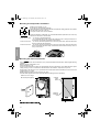
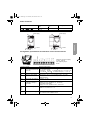
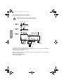
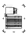
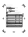
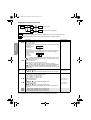
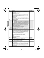
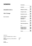
<< Back ATV11.book Page 1 Mercredi, 22. mai 2002 10:33 10 << Back Guide d’exploitation User’s manual Bedienungsanleitung Guía de explotación Guida all’impiego Altivar 11 Variateurs de vitesse pour moteurs asynchrones, Variable speed drives for asynchronous motors, Frequenzumrichter für Drehstrom-Asynchronmotoren, Variadores de velocidad para motores asíncronos, Variatori di velocità per motori asincroni. $79//////(8 FRANÇAIS 9DULDWHXUVGHYLWHVVHSRXUPRWHXUVDV\QFKURQHV ENGLISH 9DULDEOHVSHHGGULYHVIRUDV\QFKURQRXVPRWRUV DEUTSCH Frequenzumrichter für Drehstrom-Asynchronmotoren, ESPAÑOL 9DULDGRUHVGHYHORFLGDGSDUDPRWRUHVDVtQFURQRV Página 37 ITALIANO ATV11.book Page 2 Mercredi, 22. mai 2002 10:33 10 Variatori di velocità per motori asincroni Pagina 49 Page 1 Page 13 Seite 25 ATV11.book Page 13 Mercredi, 22. mai 2002 10:33 10 Steps for Setting Up the Drive 1 - Fit the drive 2 - Connect the following to the drive: • The line supply, ensuring that it is: - within the voltage range of the drive - voltage free • The motor, ensuring that its coupling corresponds to the supply voltage • The control via the logic inputs • The speed reference via the logic or analog inputs 3 - Switch on the drive, but do not give a run command • The nominal frequency (bFr) of the motor, if it is other than 50 Hz for the E range or other than 60 Hz for the U range (only appears the first time the drive is switched on). • The ACC (Acceleration) and dEC (Deceleration) parameters. • The LSP (Low speed when the reference is zero) and HSP (High speed when the reference is maximum) parameters. • The ItH parameter (Motor thermal protection). • The preset speeds SP2-SP3-SP4. • The speed reference if it is other than 0 - 5 V (0 -10V or 0 -20mA or 4 -20mA). 5 - Configure the following in the drC menu: The motor parameters, only if the factory configuration of the drive is not suitable. 6 - Start the drive Factory configuration The Altivar 11 is factory-configured for the most common operating conditions: • Logic inputs: - LI1, LI2 (2 directions of operation): 2-wire control on transition, LI1 = forward, LI2 = reverse. - LI3, LI4: 4 preset speeds (speed 1 = speed reference or LSP, speed 2 = 10 Hz, speed 3 = 25 Hz, speed 4 = 50 Hz). • Analog input AI1: speed reference (0 + 5 V). • Relay R1: the contact opens in the event of a fault (or drive off) • DO output: analog output, image of the motor frequency. If the factory configuration is not suitable, the FUn menu can be used to modify the functions and the I/O assignments. Dimensions H = G a = = = c G a c = = H = 4 = 2 ATV 11H a b mm mm c mm G mm H mm U05// E, U ranges U09// U range 72 142 6125 60±1 131±1 2 x 5 U09// E range U12// E range U18M/ E range 72 142 6138 60±1 120±1 2 x 5 U18M/ U range 72 147 138 60±1 131±1 2 x 5 U18F1 U range U29// E, U ranges U41// E, U ranges 117 142 156 106±1 131±1 4 x 5 ATV 11P a b mm mm c mm G mm H mm all ratings 72 101 60±1 131±1 2 x 5 142 Ø mm Ø mm 13 ENGLISH 4 - Configure the following: ATV11.book Page 14 Mercredi, 22. mai 2002 10:33 10 Mounting and Temperature Conditions ≥ 50 mm ≥d ≥d ≥ 50 mm Install the unit vertically, at ± 10°. Do not place it close to heating elements. Leave sufficient free space to ensure that the air required for cooling purposes can circulate from the bottom to the top of the unit. Free space in front of unit: 10 mm minimum. When IP20 protection is adequate, it is recommended that the protective cover on the top of the drive is removed, as shown below. ENGLISH • From -10°C to 40°C: • d ≥ 50 mm: no special precautions. • d = 0 (mounted side by side): remove the protective cover on the top of the drive, as shown below (the degree of protection becomes IP20). • From 40°C to 50°C: • d ≥ 50 mm: remove the protective cover on the top of the drive, as shown below (the degree of protection becomes IP20). • From 50°C to 60°C: • d ≥ 50 mm: remove the protective cover on the top of the drive, as shown below (the degree of protection becomes IP20), and derate the drive nominal current by 2.2% for every °C above 50°C. . Mounting the drives on machines ATV 11P////// drives can be mounted on (or in) a steel or aluminium machine frame, observing the following conditions: Maximum ambient temperature: 40 °C Vertical mounting at ± 10° The drive must be fixed at the centre of a support (frame) which is a minimum of 10 mm thick and with a square cooling area (S) of 0.12 m2 minimum for steel and 0.09 m2 for aluminium, exposed to the open air. Support area for the drive (min 142 x 72) machined on the frame with a surface smoothness of 100 µm max and a roughness of 3.2 µm max. Mill the tapped holes lightly in order to remove any burrs. Coat the whole support surface of the drive with thermal contact grease (or equivalent). m 131 mm ≥10 m 2 tapped holes Ø M5 ≥142 mm Attach the drive using 2 M5 screws (not supplied). S Minimum machined area 60 mm ≥72 mm 9HULI\WKHWKHUPDOVWDWHRIWKHGULYHE\FKHFNLQJSDUDPHWHUW+G683PHQXWRFRQILUPWKDWWKH GULYHKDVEHHQPRXQWHGFRUUHFWO\ 14 ATV11.book Page 15 Mercredi, 22. mai 2002 10:33 10 Power Terminals Maximum connection capacity Tightening torque in Nm AWG mm2 U05///, U09///, U18M// AWG 14 1.5 0.75 U18F1/, U29///, U41/// AWG 10 4 1 Power supply Power supply To motor To braking module To braking module ENGLISH Altivar ATV 11/ To motor Terminal Function RC RA + 15V LI 4 LI 3 LI 2 LI 1 DO + 5V AI 1 0V Not used RA RC Arrangement, specifications and functions of the control terminals - Maximum connection capacity: 1.5 mm2 - AWG 16 - Max. tightening torque: 0.5 Nm. Electrical characteristics Fault relay contact Min. switching capacity: 10 mA for 24 V $ (open if there is a fault or the Max. switching capacity: • 2 A for 250 V "and 30 V $on inductive load (cos ϕ = 0.4 - L/R = 7 ms) drive is off) • 5 A for 250 V " and 30 V $ on resistive load (cos ϕ = 1- L/R = 0) 0V I/O common 0V AI1 Voltage or current analog input Analog input 0 + 5V or 0 + 10 V: impedance 40 kΩ, 30 V max. Analog input 0 - 20mA or 4 - 20mA: impedance 250 Ω (with no additional resistor) +5V Power supply for reference potentiometer 2.2 to 10 kΩ • Precision: - 0 + 5% • Max. current available: 10 mA DO Output which can be configured as analog or logic output PWM open collector analog output at 2 kHZ: • voltage 30 V max., impedance 1 kΩ, 10 mA max. Open collector logic output: • voltage 30 V max., impedance 100 kΩ, 50 mA max. LI1 LI2 LI3 LI4 Programmable logic inputs • Power supply + 15 V (max. 30 V), Impedance 5 kΩ • State 0 if < 5 V, state 1 if > 11 V + 15V Logic input power supply + 15 V ± 15% protected against shorts-circuits and overloads. Max. customer current available 100 mA 15 ATV11.book Page 16 Mercredi, 22. mai 2002 10:33 10 Wiring diagram for factory settings • Supply terminals at the top, motor terminals at the bottom • Connect the power terminals before the control terminals Single phase supply 100...120 V N L1 ATV11////F1/ L1 ATV11////M2/ L2 Single phase supply 200...230 V L3 a 3-phase motor 200...230 V PA PB M 3 LI4 +15 V DO LI2 LI1 LI3 0V AI1 +5V PA / + PC / - + W - V1 W1 V U RC (1) RA L1 L2 (2) ATV11////M3/ U1 ENGLISH 3-phase supply 200...240 V Reference potentiometer (3) Braking module and resistor, optional (1) Fault relay contacts, for remote indication of the drive status. (2) Internal + 15 V. If an external source is used (+ 24 V max.), connect the 0 V of the source to the 0V terminal, and do not use the + 15 V terminal on the drive. (3) Galvanometer or low level relay. Note: Fit interference suppressors to all inductive circuits near the drive or coupled to the same circuit (relays, contactors, solenoid valves, etc) Choice of associated components: See the Altivar 11 catalog. 16 ATV11.book Page 17 Mercredi, 22. mai 2002 10:33 10 Functions of the display and the keys • Exits a menu or parameter, or aborts the displayed value to return to the previous value in the memory Altivar 11 • 3 "7-segment" displays ESC ENT • Returns to the previous menu or parameter, or increases the displayed value Pressing • Goes to the next menu or parameter, or decreases the displayed value does not store the selection. ENT ENGLISH Save the selection: Example: Parameter or • Enters a menu or a parameter, or saves the displayed parameter or value Value or assignment 1 flash (save) The display flashes when a value is stored. (Next parameter) Normal display, with no fault present and no startup: - rdY: Drive ready - 43.0: Display of the parameter selected in the SUP menu (default selection: frequency reference). - dcb: DC injection braking in progress - nSt: Freewheel stop If there is a fault, it is shown with a flashing display. 17 ATV11.book Page 18 Mercredi, 22. mai 2002 10:33 10 1st level adjustment parameters Displays the drive status XXX ENGLISH bFr Menu: Motor control drC Menu: Application functions Fun Menu: Monitoring SUP ESC 1st level adjustment parameters ESC ESC Menus ESC The parameters in clear boxes can only be modified when the drive is stopped and locked. Parameters in shaded boxes can be modified with the drive operating or stopped. Code B&R !## D%# ,30 (30 )T( 30 30 30 !)T Description Adjustment range Factory setting Motor frequency 50 Hz or 60 Hz 50 (E range) or 60 (U range) This parameter is only visible the first time the drive is switched on. It can be modified at any time in the FUn menu. Acceleration ramp time 0.1 s to 99.9 s 3 Range: 0 Hz to motor nominal frequency FrS (parameter in drC menu). Deceleration ramp time 0.1 s to 99.9 s 3 Range: motor nominal frequency FrS (parameter in drC menu) to 0 Hz. Low speed 0 Hz to HSP 0 LSP to 200 Hz = bFr Motor frequency to 0. High speed Motor frequency to max. reference. Check that this setting is appropriate for the motor and the application. Motor thermal current 0 to 1.5 In (1) According to drive rating Current used for motor thermal protection. Set ItH to the nominal current marked on the motor rating plate. The memory of the motor thermal state returns to zero when the drive is switched off. 2nd preset speed (2) 0.0 to 200 Hz 10 3rd preset speed (2) 0.0 to 200 Hz 25 4th preset speed (2) 0.0 to 200 Hz 50 Configuration of the analog input 5U, 10U, 0A, 4A 5U 5: voltage 0 - 5 volts (internal power supply) 5: voltage 0 - 10 volts (external power supply) !: current 0 - 20 mA !: current 4 - 20 mA - (1) In = nominal drive current (2) The preset speeds only appear if the corresponding function has remained at the factory setting or has been reconfigured in the FUn menu. 18 ATV11.book Page 19 Mercredi, 22. mai 2002 10:33 10 Motor control menu drC Value Nominal motor voltage Value Motor nominal cosine ϕ The parameters in clear boxes can only be modified when the drive is stopped and locked. Parameters in shaded boxes can be modified with the drive operating or stopped. Code 5N3 &R3 3T! &,' 5&R N#R #,) N3, 3,0 #/3 Description Adjustment range Factory setting Nominal motor voltage marked on the rating plate. 100 to 500 V Acc. to rating Nominal motor frequency marked on the rating plate. 40 to 200 Hz 50 / 60Hz dep. on bFr Frequency loop stability 0 to 100% when stopped 1 to 100% when operating 20 0 to 100% when stopped 1 to 100% when operating 20 ENGLISH Drive performance can be optimised by entering the values marked on the motor rating plate Value too high: lengthening of response time Value too low: overspeed, possible instability. Frequency loop gain Value too high: overspeed, instability. Value too low: lengthening of response time IR compensation 0 to 200% Used to optimise the torque at very low speed, or to adapt to special cases (example: for motors connected in parallel, lower UFr). 50 Nominal motor current marked on the rating plate 0.25 to 1.5 In (1) Acc. to rating Limiting current 0.5 to 1.5 In (1) 1.5 In Nominal motor slip 0 to 10.0 Hz Acc. to rating Calculate using the formula: nSL = parameter FrS x (1 - Nn/Ns) Nn = nominal motor speed marked on the rating plate Ns = motor synchronous speed Slip compensation 0 to 150% (of nSL) 100 Used to adjust the slip compensation around the value set by the nominal motor slip nSL, or to adapt to special cases (example: for motors connected in parallel, lower SLP). Nominal motor cosine ϕ marked on the rating plate 0.50 to 1.00 Acc. to rating (1) In = nominal drive current 19 ATV11.book Page 20 Mercredi, 22. mai 2002 10:33 10 Application functions menu FUn ENT FUn ESC ESC tCC Type of control ENT ESC ESC FCS Reminder of the configuration ENT The parameters in clear boxes can only be modified when the drive is stopped and locked. Parameters in shaded boxes can be modified with the drive operating or stopped. Code Description T#T RR3 trn Type of 2-wire control (parameter can only be accessed if tCC = 2C): : state 0 or 1 is taken into account for running or stopping. : a change of state (transition or edge) is necessary to initiate operation, in order to prevent accidental restarts after a power supply interruption. : same as LEL, but the "forward" input always takes priority over the "reverse" input. ,%, TRN 0&/ Reverse : function inactive to : choice of the input assigned to the reverse command N/ ,) 03 ,)! ,) Preset speeds If LIA and LIb = 0: speed = reference on AI1 If LIA = 1 and LIb = 0: speed = SP2 If LIA = 0 and LIb = 1: speed = SP3 If LIA = 1 and LIb = 1: speed = SP4 Assignment of input LIA : function inactive to : choice of the input assigned to LIA Assignment of input LIb : function inactive to : choice of the input assigned to LIb SP2 is only accessible if LIA is assigned, SP3 and SP4 if LIA and LIb are assigned. N/ ,) ,) ,)B N/ ,) ,) 30 30 30 2nd preset speed, adjustable from 0.0 to 200 Hz (1) 3rd preset speed, adjustable from 0.0 to 200 Hz (1) 4th preset speed, adjustable from 0.0 to 200 Hz (1) (1) The preset speeds can also be accessed in the 1st level adjustment parameters. 20 Factory setting Type of control = 2-wire control 2C = 3-wire control 2-wire control: The open or closed state of the input controls the running or stopping. +15 V LI1 LIx Example of wiring: LI1: forward LIx: reverse 3-wire control (pulse control): a "forward" or "reverse" pulse is sufficient to command starting, a "stop" pulse is sufficient to command stopping. Example of wiring: +15 V LI1 LI2 LIx LI1: stop LI2: forward LIx: reverse To change the assignment of tCC press the "ENT" key for 2 s. This causes the following functions to return to factory setting: rrS, tCt, Atr, PS2 (LIA, LIb). !#T # # ENGLISH T## if tCC = 2C: LI2 if tCC = 3C: LI3 if tCC = 2C: LI3 if tCC = 3C: LI4 if tCC = 2C: LI4 if tCC = 3C: nO 10 25 50 ATV11.book Page 21 Mercredi, 22. mai 2002 10:33 10 Code Description R3& 3T0 N/ ,) ,) ,) !# D% N/ ,) ,) 2nd acceleration ramp time, adjustable from 0.1 to 99.9 s 2nd deceleration ramp time, adjustable from 0.1 to 99.9 s nO 5.0 5.0 nO Controlled stop on loss of line supply : locking of the drive and freewheel stopping of the motor : stop according the valid ramp (dEC or dE2) : fast stop, the stopping time depends on the inertia and the braking ability of the drive. N/ &R0 &3T BR! !D# Second ramp Assignment of the 2nd ramp control input : function inactive to : choice of assigned input AC2 and dE2 are only accessible if LI is assigned. YES Deceleration ramp adaptation : function inactive : This function automatically increases the deceleration time, if this has been set at too low a value for the inertia of the load, thus avoiding the overvoltage fault. N/ 9%3 !#T ENGLISH R0 Factory setting nO Fault reset : function inactive to : choice of the input assigned to this function The reset takes place at a transition on the input (rising edge: 0 to 1). It is only authorised if the fault has disappeared. Automatic DC injection YES Operating mode : function inactive : DC injection on stopping, duration adjustable via tdC, when operation is no longer controlled and the motor speed is zero. The value of this current can be adjusted via SdC. : Continuous DC injection on stopping, when operation is no longer controlled and the motor speed is zero. The value of this current can be adjusted via SdC. In 3-wire control the injection is only active when LI1 is at 1. tdC is only accessible if ACt = YES, SdC if ACt = YES or Ct. N/ 9%3 #T 3&T TD# 3D# !#T 3&R Injection time on stopping, adjustable from 0.1 to 30.0 s Injection current, adjustable from 0 to 1.2 In (In = nominal drive current) Switching frequency Frequency range : random frequency around 2 or 4 kHz according to SFr : fixed frequency of 2 or 4 kHz according to SFr : fixed frequency of 8, 12 or 16 kHz according to SFr - ,&R ,& (& Switching frequency: - : 2 kHz (if ACt = LF or LFr) - : 4 kHz (if ACt = LF or LFr) - : 8 kHz (if ACt = HF) : 12 kHz (if ACt = HF) : 16 kHz (if ACt = HF) When SFr = 2 kHz, the frequency automatically changes to 4 kHz at high speed. When SFt = HF, the selected frequency automatically changes to the lower frequency if the thermal state of the drive is too high. It automatically returns to the SFr frequency as soon as the thermal state permits. 0.5 0.7 In LF 4 (if ACt = LF or LFr) 12 (if ACt = HF) 21 ATV11.book Page 22 Mercredi, 22. mai 2002 10:33 10 Code Description &,R Factory setting nO Catch on the fly Enables a smooth restart if the run command is maintained after the following events: - loss of line supply or disconnection - fault reset or automatic restart - freewheel stop. The motor resumes from the estimated speed at the time of the restart then follows the ramp to the reference speed. This function requires 2-wire control (tCC = 2C) with tCt = LEL or PFO. : function inactive : function active The function intervenes at each run command, resulting in a slight delay (1 second max.). If continuous automatic injection braking has been configured (Ct) this function cannot be activated. N/ 9%3 !#T ENGLISH D/ !TR B&R )0, 3#3 22 &TD #TD Analog/logic output DO rFr Assignment : not assigned : analog output = current in the motor. The full signal corresponds to 200% of the nominal drive current. : analog output = motor frequency. The full signal corresponds to 100% HSP. : logic output = frequency threshold reached, closed (state 1) if the motor frequency exceeds the adjustable threshold Ftd. : logic output = reference reached, closed (state 1) if the motor frequency is equal to the reference. : logic output = current threshold reached, closed (state 1) if the motor current exceeds the adjustable threshold Ctd. Ftd is only accessible if ACt = FtA, Ctd is only accessible if ACt = CtA. N/ /#R R&R &T! 3R! #T! frequency threshold, adjustable from 0 to 200 Hz = bFr current threshold, adjustable from 0 to 1.5 In (In = nominal drive current) In Automatic restart nO : function inactive : Automatic restart, after locking on a fault, if the fault has disappeared and the other operating conditions permit the restart. The restart is performed by a series of automatic attempts separated by increasingly long waiting periods: 1 s, 5 s, 10 s, then 1 min for the following periods. If the restart has not taken place after 6 min, the procedure is aborted and the drive remains locked until it is disconnected and then reconnected. The following faults permit this function: OHF, OLF, ObF, OSF, PHF. The drive fault relay remains activated if this function is active. The speed reference and the operating direction must be maintained. This function is only accessible in 2-wire control (tCC = 2C) with tCt = LEL or PFO. Check that an accidental start does not present any danger to personnel or equipment. N/ 9%3 Motor frequency (Same as bFr 1st level adjustment parameter) Set to 50 Hz or 60 Hz, taken from the motor rating plate. 50 (E range) or 60 (U range) Line phase loss fault configuration This parameter is only accessible on 3-phase drives. : inhibition of the line phase loss fault : monitoring of the line phase loss fault YES N/ 9%3 Configuration backup nO : function inactive : saves the current configuration to the EEPROM memory. SCS automatically switches to nO as soon as the save has been performed. This function is used to keep another configuration in reserve, in addition to the current configuration. When drives leave the factory the current configuration and the backup configuration are both initialised to the factory configuration. N/ 9%3 ATV11.book Page 23 Mercredi, 22. mai 2002 10:33 10 Code  Description Factory setting nO Reminder of the configuration : function inactive : the current configuration becomes identical to the backup configuration previously saved by SCS. rEC is only visible if the backup has been carried out. FCS automatically switches to nO as soon as this action has been performed. : the current configuration becomes identical to the factory setting. FCS automatically switches to nO as soon as this action has been performed. For rEC and InI to be taken into account the ENT key must be held down for 2 s. N/ R%# )N) Monitoring menu SUP ENT ESC ESC FrH ESC tHd ESC Value Frequency reference ENT ENT Value Drive thermal state When the drive is running, the value displayed is that of one of the monitoring parameters. The default value which is displayed is the motor reference (parameter FrH). While the value of the required new monitoring parameter is being displayed, the "ENT" key must be pressed a second time to confirm the change of monitoring parameter and to store it. From then on the value of this parameter will be displayed during operation (even after the drive has been switched off). If the new choice is not confirmed by pressing the "ENT" key for a second time, the drive will return to the previous parameter after it has been switched off. The following parameters can be accessed, with the drive stopped or running. Code &R( R&R ,#R 5,N T(R T(D Parameter Unit Display of the frequency reference (factory configuration) Hz Display of the output frequency applied to the motor Hz Display of the motor current A Display of the line voltage V Display of the motor thermal state: 100% corresponds to the nominal thermal state. % Above 118%, the drive trips on an OLF fault (motor overload). It can be reset below 100%. Display of the drive thermal state: 100% corresponds to the nominal thermal state. % Above 118%, the drive trips on an OHF fault (drive overheating). It can be reset below 80%. 23 ENGLISH SUP ATV11.book Page 24 Mercredi, 22. mai 2002 10:33 10 Faults - Causes - Remedies Starter does not start, no fault displayed • Check that the run command input(s) have been actuated in accordance with the chosen control mode. • When the drive is switched on, at a manual fault reset, or after a stop command, the motor can only be powered once the "forward" and "reverse" commands have been reset. If they have not been reset, the drive will display "rdY" or “nSt” but will not start. Faults displayed The cause of the fault must be removed before resetting. Faults SOF, OHF, OLF, OSF, ObF, and PHF can be reset via a logic input if this function has been configured. Faults OHF, OLF, OSF, ObF, and PHF can be reset via the automatic restart function, if this function has been configured. All faults can be reset by switching the drive off then on again. Fault Remedy overcurrent • Ramp too short, check the settings. • Inertia or load too high, check the size of the motor/drive/load. • Mechanical locking, check the state of the mechanism. /#& ENGLISH 3#& • Check the cables connecting the drive to the motor, and the insulation of the motor. motor short-circuit, insulation fault )N& internal fault • Check the environment (electromagnetic compatibility). • Replace the drive. configuration fault • Return to factory settings or call up the backup configuration, if it is valid. See parameter FCS in the FUn menu. #&& 3/& overspeed /(& • Instability, check the motor, gain and stability parameters. • Driving load too high, add a braking module and resistor and check the size of the motor / drive / load. drive overload • Check the motor load, the drive ventilation and the environment. Wait for the drive to cool before restarting. motor overload • Check the setting of the motor thermal protection, check the motor load. Wait for the drive to cool before restarting. /,& /3& • Check the line voltage. overvoltage /B& overvoltage during deceleration 0(& line phase failure 53& • Braking too harsh or driving load. Increase the deceleration time, add a braking resistor if necessary and activate the brA function if it is compatible with the application. This protection only operates with the drive on load. • Check the power connection and the fuses. • Reset. • Check the line supply / drive compatibility. • If there is an unbalanced load, inhibit the fault via IPL = nO (FUn menu). • Check the voltage and the voltage parameter. undervoltage #R& charging circuit 24 • Replace the drive. ATV11.book Page 1 Mercredi, 22. mai 2002 10:33 10 VVDED302031 W9 1623801 01 12 A02 028297 2002-05