1
Reconfigurable Sparse Matrix-Vector
Multiplication on FPGAs
Salma Mirza and Russell Tessier
Dept. of Electrical and Computer Engineering
University of Massachusetts
Amherst, MA 01003
Abstract—Cache-based, general purpose CPUs perform at a
small fraction of their maximum floating point performance when
executing memory-intensive simulations, such as those required
for sparse matrix-vector multiplication. This effect is due to the
memory bottleneck that is encountered with large arrays that
must be stored in dynamic RAM. An FPGA core designed for a
target performance that does not unnecessarily exceed the
memory imposed bottleneck can be distributed, along with
multiple memory interfaces, into a scalable architecture that
overcomes the bandwidth limitation of a single interface.
Interconnected cores can work together to solve a computing
problem and exploit a bandwidth that is the sum of the
bandwidth available from all of their connected memory
interfaces. This work demonstrates this concept of scalability with
two memory interfaces through the use of an available FPGA
prototyping platform. It is shown that our reconfigurable
approach is scalable as performance roughly doubles when two
FPGAs are used for computation instead of one.
Index Terms—FPGA, Sparse matrix-vector multiply
I. INTRODUCTION
S
parse matrix-vector multiply (SMVM) computations
perform poorly on cache-based CPUs because they are
highly memory intensive, have large sizes and require frequent
data updates. As an example, we consider sparse matrices that
arise from the finite element analysis used in several
disciplines to find approximate solutions to boundary value
problems. Sparse matrix-vector multiplication involves
iteratively multiplying a sparse matrix with a dense vector that
changes on every iteration. This is a stream-based computation
that lacks temporal locality and restricts the performance
advantage that a cache-based CPU would have as a result of
repetitive data use.
As cache hits in SMVM are rare, the speed of the algorithm
is entirely dictated by the sequential and random memory
access bandwidth. This “memory bottleneck” causes
processors to run at a small fraction of their peak floating point
rate for scientific computations resulting in a performance of
MFlops as opposed to GFlops. The floating point performance
is observed to drop down to as low as 2.7% of the peak value
of the CPU. An approach to overcome this memory wall by
using a system of FPGAs with external memory banks as a
math co-processor is implemented. The FPGA-based system is
demonstrated to be scalable; the memory bandwidth of the
FPGAs and hence the floating point performance of the
J. Blair Perot
Dept. of Mechanical and Industrial Engineering
University of Massachusetts
Amherst, MA 01003
FPGA-based implementation can be linearly increased by
increasing the number of FPGAs or the memory interfaces per
board.
Section II explains the motivation for implementing the
SMVM problem on a system of FPGAs. The floating point
performance for scientific computations is non-contingent on
the clock frequency [1]. The use of multiple cores is
complicated because concurrent techniques other than multithreading must be used by the programmer [2]. Increases in
processor clock speed and in the number of cores per
processor are current microprocessor industry trends. For
sparse matrix-vector multiply these improvements are
unhelpful because they do not address the memory bottleneck.
Section III gives an overview of the SMVM problem that
arises in an iterative simulation of two-dimensional heat
transfer. The differences between the sparsity patterns of the
sparse matrix for this problem are highlighted and an alternate
data structure that can store a sparse row and a sparse column
matrix with equal efficiency is explained.
Section IV looks into previous work for similar problems
that use approaches that are different than ours. Matrices
undergoing computation are stored in formats that are either
efficient for a sparse row format or a sparse column format,
but not both. The problem size constraints which arise due to
limited on-chip memory storage of sparse matrices and dense
vectors are explained.
Section V details our choice of FPGA board for this
implementation. Candidate boards are required to have dense
off-chip memory modules and inter-board communication
abilities.
In Section VI we detail the implementation algorithm for
SMVM on multiple boards. In our approach, operands,
operators and memory addresses that include board address
information are organized into packets to distribute
computations between FPGAs. A system of FIFOs is used to
implement a streaming paradigm on these packets, where data
is fetched from DRAM memory if FIFOs are non-empty. Data
values stored in a FIFO is subsequently processed. Based on a
fetch or write memory address, data packets are routed to a
destination FPGA by a router sub-system. The implementation
algorithm is exactly the same for a gather or a scatter
operation, and hence, the efficiency of either operation
remains the same. The size of a matrix is limited by the size of
the external memory. For bigger matrices, this architecture can
be scaled by using more FPGAs or bigger memory modules.
Section VII contains the results and some conclusions for
this work. A single board implementation performs at 12
MFlops. A two-board implementation performs at 24 MFlops,
indicating that our system is scalable. Section VIII highlights
planned future work.
The construction and storage of a sparse matrix prior to
computation is difficult, expensive and unnecessary. If
constructed at all, the sparse matrix should be stored in an
alternate representation, either a compressed row or
compressed column representation, whichever may be more
appropriate for the matrix at hand [3]. Computer codes that
actually build matrices slow down the simulations because of
the memory access times involved. This issue ultimately
restricts the accuracy at which the simulations can be
performed in a constrained time period.
III. BACKGROUND
II. MOTIVATION
Simulations allow scientists to quantitatively predict results
of real-life phenomena for a range of input conditions and with
a programmable degree of accuracy. In many cases,
simulations are preferred to physical experiments because they
are often cheaper, faster and less dangerous than these types of
experiments. For a reasonably good mathematical model, the
accuracy of the simulations is given by how closely a
simulation setup can imitate a physical experimental setup. To
increase accuracy, the problem must be made larger. This
translates to an increase in the number of computations, which
in turn is constrained by the available computing resources and
their efficiency.
Low-cost commodity computers are most often used in
clusters for scientific simulations. Commodity computers
utilize a cache-based architecture which is ill-suited for
streaming applications. SMVM performs poorly on cachebased CPUs because of the vast and constantly changing data
associated with iterative simulations. The data set is usually
too large to fit in the CPU cache and exhibits little temporal
locality, making cache hits rare. The speed of computation is
limited by memory access times that, typically, are at least ten
times slower than the time taken to perform an operation on
the CPU. This problem is particularly apparent in the DAXPY
(double precision y = ax + y) operation.
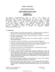
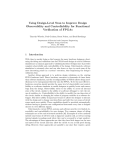
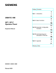
Consider the problem of two-dimensional heat transfer on
an unstructured mesh, as shown in Figure 1. To discretize the
partial differential equations associated with this problem, the
mesh is divided into smaller domains. In practice, the mesh
may consist of 100,000 sub-domains for a 2-D problem, and a
million tetrahedras for a 3-D problem. Dividing the mesh into
smaller sub-domains results in a more accurate solution, but
also involves more data and intensified computation. For the
purpose of simplification, we consider a triangle that is a part
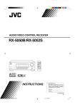
of a larger mesh, as shown in Figure 1. The temperature
unknowns are located at the four vertices and are calculated
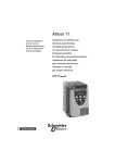
iteratively in two steps. The temperature gradient along the
edges is calculated as the first step. Roughly, this value is the
difference in temperature at the vertices that connect an edge
divided by the length of the edge as shown in Figure 2.
y1 = k1
y5 = k 5
x1 − x 4
L
5
y3 = k 3
x1 − x 3
L
3
x1 − x 2
L1
Figure 2: The Gradient Operation (Gather)
This is a gradient operation and in matrix form, it is
represented by y = Gx
y1
y2
y
3
y 4
Figure 1: Discretization of a PDE over a triangular mesh
=
1
L
1
0
1
L3
0
1
L5
1
L1
1
L2
−
0
0
0
0
1
L2
1
−
L3
1
L4
−
0
0
0
0
1
−
L4
1
−
L5
x1
x2
x
3
x 4
The matrix G is a sparse matrix. Every row of G contains
exactly two non-zero items. For simplicity, we refer to nonzero values as items. In relation to the problem at hand, the
number of columns in the matrix depends on the number of
nodes and the number of rows depends on the total number of
edges. The location of items in a row indicates the nodes
connected to each edge. The value of the item represents the
length of each edge. The values in a row are repeated except
for a minus sign. For example, in row 1, the items are located
in column 1 and column 2, indicating that edge 1 is between
nodes x1 and x2 and has length L1.
y1*k 1 + y 3*k 3 + y5*k 5
y1*k1
x1
L1
x2
y *k
5 5
L3
L5
L2
y 3*k 3
x4
x3
L4
Figure 3. The Divergence Operation (Scatter)
Each row has two items (which are identical except for the
sign) even when the number of unknowns is huge (e.g.
100,000), so the matrix remains extremely sparse as it
increases in size. As a result, it is best if this matrix is not
constructed to include all or most of the points. Matrix G can
be efficiently stored in a compressed row format given its
sparsity pattern.
To solve for y without generating an explicit (sparse) matrix
for the gradient operation, we construct the Edge to Node
[E2N] data structure which holds the connectivity information
for the mesh. The E2N structure contains the pointer
information specifying which two nodes define each edge. In
this sense, the E2N data structure is equivalent to a
compressed row sparse matrix because both hold the same
connectivity information. The E2N data structure for the
problem under consideration is given by:
x1 x2 x1 x3 x1
E2N =
x2 x3 x3 x4 x4
Then, in pseudo-code, the gradient operation can be
implemented with a single line (and without generating an
explicit matrix) as:
Equation 1:
for (e = 0; e < num_edges; e + + ) {
This represents the discrete divergence operation and in
matrix form it is given by: z =Dy
z
1
z2
z3
z 4
=
k
1
- k
1
0
0
0
k2
- k2
0
k3
0
- k3
0
0
0
k4
- k4
k5
0
.
0
- k 5
y
1
y2
y3
y 4
y 5
Matrix D, like matrix G, is sparse. Every column of D
contains exactly two items. Matrix D is best stored in the
compressed column format given its sparsity pattern, or it can
be directly implemented using the E2N data structure
discussed earlier. In this case, the E2N data structure can be
considered equivalent to the compressed column format.
In pseudo-code, the discrete divergence operation can be
implemented without generating an explicit matrix as:
Equation 2:
z = 0;
for (e = 0; e < num_edges; e + + ) {
z[E2N[1, e]] + = y[e] * k[e];
z[E2N[2, e]] − = y[e] * k[e]; }
y[e] + = 1/Li[e] * x[E2N[1, e]] ;
y[e] – = 1/Li[e] * x[E2N[2, e]] ;
}
In the above operation, indirect memory reads (gather) of
the type x = a[i] of the node temperatures are performed from
the dense vectors that hold this information to calculate the
gradient at each edge. Henceforth, we refer to the gradient
operation as the “gather operation”.
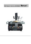
The second step multiplies the gradient on each edge (‘y’ as
obtained in the first step) by the conductivity along the edge
(‘k’), to obtain the flux along each edge. The fluxes associated
with each edge attached to a node are the summed up to obtain
temperature unknowns, as shown in Figure 3.
In the above operation, indirect memory writes of the type
a[i] = x are performed in which the value at each edge is
“scattered” to the nodes that contain it. Henceforth, we refer to
the discrete divergence operation as the “scatter operation”.
Forcing column-sparse matrices into a compressed row
format or row-sparse matrices in the compressed column
format is unnatural and inefficient. Using the E2N data
structure, it is possible to store both matrices efficiently. For
this implementation of SMVM, the sparse matrices are stored
using the E2N data structure.
IV. PREVIOUS WORK
Several previous research projects have implemented
SMVM algorithms using FPGAs. de Lormier and DeHon
developed a multi-FPGA approach which uses matrices
available in compressed row format [4]. As discussed, some
sparse matrices are best represented in compressed row
format, while others are best represented in compressed
column format. Forceful representation of a matrix in a
compressed row format might not be efficient. The limited size
of the source and destination vectors (about 10,000 values)
allows them to be stored inside FPGA embedded memory.
This approach is hence not scalable to larger problem sizes.
This design was also optimized for repeated multiplication by
the same matrix. Inter-FPGA communication is coordinated at
compile time and hard-coded into FPGA hardware. Although
efficient, this approach requires recompilation for every
matrix. Recompilation is unsuitable for dynamic problems
where matrices are continually changing.
TABLE I
MEMORY MANAGEMENT
Data
Notation
Edge to node matrix
Temperature gradient along edge
Length of edge
Conductivity along edge
Temperature at each node
Sum of fluxes at each node
E2N[1/2,e]
y[e]
Li[e]
k[e]
x[E2N[i,e]]
z[E2N[i,e]]
Operation
Gather, Scatter
Gather
Gather
Scatter
Gather, Scatter
Scatter
TABLE 2
PACKET STRUCTURE
Data contained in each packet
Multiplier value
Source address
Store/Destination address
Sign value
Source board information
Store/ Destination board information
Gather
Scatter
Li[e]
k[e]
E2N[1/2,e]
&z[e]
&y[e]
E2N[1/2,e]
+/+
Included in source address
Included in destination address
V. IMPLEMENTATION PLATFORM
Zhuo and Prasanna also developed a SMVM approach
based on FPGAs which uses a matrix represented in
compressed row format [5]. For this implementation, the entire
source value vector is again placed in each FPGA. This
restriction is a limiting factor on problem size and scalability.
A faster implementation was developed by Sun, Peterson
and Storaasli [6]. They designed an FPGA approach which
uses a non-conventional data format and takes advantage of a
specialized accumulator. This approach is again limited to
small matrices and uses a prescribed (but slightly nonstandard)
matrix format as well as the assumption of an explicitly-built
matrix.
Our algorithm differs considerably from these prior designs
by focusing on improving the memory bandwidth rather than
improving the performance of the FPGA implementation.
Previous works have bypassed the memory bottleneck by
placing matrix data in FPGA memory blocks. This approach is
convenient for small problems that can conveniently fit in the
memory blocks. However, for problems with larger data sizes,
this architectural approach is not scalable. In our approach, the
data is stored explicitly in on-board memory and accessed by
the FPGA at DDR2 data rates. This data is stored in multiple
memory banks and the FPGA’s capability of accessing
multiple memory banks is used to overcome the memory wall.
In this scheme, our algorithm is closer to that of El-kurdi,
Gross, and Giannocopolos, which also focuses on very large
vectors that cannot reside in FPGA embedded memory [7].
The algorithm implemented by DuBois et al. can work on very
long vectors, but still assumes an explicit matrix is present in a
prescribed format [8]. Matrix data is stored in external DRAM
memory.
The main criteria used to choose a board for
experimentation was the presence of off-chip memory, the
presence of on-chip hardware multipliers and an inter-board
communication ability. The DE3 boards available from
Terasic provided these capabilities [9]. Each board contains a
Stratix III EP3SL150 FPGA with 142,000 logic elements
(LEs) and 384 18x18-bit multiplier blocks. Each board has a
single DDR2 SO-DIMM socket with a maximum capacity of
up to 4GB. Inter-board communication is through a 128-pin
low voltage differential signaling (LVDS) connector.
VI. IMPLEMENTATION ALGORITHM
In this SMVM implementation, both scatter and gather
operations can be performed using the same architecture with
the same efficiency and without logic reconfiguration. The
gather and the scatter operations discussed in Section III
require the arrays shown in Table 1 be stored in external
memory. The packet structure for scatter and gather operations
is shown in Table 2. The compute platform can be
reconfigured for new SMVM operations simply by loading
new sparse matrix and vector information into the memory
banks.
These matrices are stored in four banks of the off-chip
memory. The term ‘banks’ does not imply the presence of
multiple memory interfaces in this case. These banks cannot be
accessed in parallel. Only one bank can be accessed at a time,
through the single memory interface. However, we continue to
use the bank structure to organize data, as if multiple interfaces
were available to us. The motivation in using this approach is
that if multiple memory interfaces were indeed available, this
data could be accessed in parallel without making any major
changes to the core. Stratifying the data into banks is also
helpful in developing estimates of how the presence of
multiple banks would improve the performance of the design.
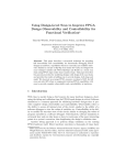
For a multiple-board implementation, the matrix is
approximately evenly divided between the external memories
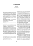
of the two boards. The gather operation takes place in a series
of ten steps as discussed below and demonstrated in Figure 4.
Step 5: On the source board, the source value (x[E2N[i,e]]) is
then fetched from the FPGA read memory bank and replaces
the source address in the data packet, which is now stored in a
FIFO called SOURCE. All memory reads are directed through
a single FIFO called RAND. If multiple memory reads are
requested through the single interface at the same time, priority
can be given to packets from the same FIFO. This approach
improves DDR controller efficiency by preventing the
controller from swapping between writes and reads to different
rows, forcing a row to be opened and closed on every
transaction.
Step 6: The compute element in the source value FPGA
multiplies L[e] and x[E2N[i,e]], replaces L[e], discards
x[E2N[i,e]] and stores the packet in a FIFO called MULT.
Step 7: The router decides if the packet should be routed to
another FPGA (puts packet in ROUTE FIFO) or will remain
on the same FPGA (puts packet in NOROUTE1 FIFO). The
result, L[e]*x[E2N[i,e]], is routed to the destination FPGA’s
NOROUTE1 FIFO. In this example, the packet is routed back
to FPGA-1.
Figure 4: The Gather Operation
Step 1: The floating point multiplier values (L[e]) are
sequentially fetched from the memory and stored in a FIFO
called SEQ0. Because it is a gather operation, the destination
addresses (for y[e]) are internally generated by the FPGA and
stored in a FIFO called ADDR (given the fact that y[e] is laid
out exactly like L[e] since they are the same size).
Step 2: The two integer destination address values (E2N[1,e]
and E2N[2,e]) are fetched sequentially from the memory and
stored in a FIFO called SEQ1.
Step 3: From the data present in SEQ0, SEQ1 and ADDR,
packets are generated for each source address. These packets
are stored in a FIFO called PACKET. Each packet contains a
± multiplier, a destination address, and the source address.
Both the source and destination addresses contain the board
identifiers of the target FPGAs. The board containing the
source address is referred to as the source FPGA and the board
containing the destination address is referred to as the
destination FPGA.
Step 4: Each packet is examined by the router to determine if
it needs to be routed to the source address on a different board
or if it can remain on the same board. Accordingly, it places
the packets in FIFOs called NOROUTE0 (for packets that stay
on the same FPGA) and ROUTE (for packets that need to be
routed). The router subsystem routes the packets from ROUTE
to the NOROUTE0 FIFO on the source FPGA. For a gather
operation this routing is required because the nodes are
randomly distributed between the FPGAs. For this example,
assume that the packet is routed to FPGA-2.
Step 8: The destination value y[e] is fetched from the memory
through RAND and the packet is stored in DEST FIFO.
Step 9: The product from Step 6 is added to or subtracted
from the destination value y[e] using the adder on the
destination FPGA. The destination data is discarded and the
packet is stored in ACCUM FIFO. Depending on the matrixbased application, this operation could also be a subtract, max,
or min function. However, the specified operation is the same
for all packets traveling through the system.
Step 10: The accumulated value is written to the appropriate
memory bank on the FPGA using the destination address.
The scatter operation operates in exactly the same way as
the gather except that the locations of the source and the
destination addresses are interchanged while constructing the
packets in Step 3. Accordingly, the packet does not need to be
routed in Step 4, because the memory bank with the source
value is attached to the same FPGA as the one with the
multiplier values. The packet goes through the router subsystem in any case to maintain a common architecture for the
gather and scatter operations. Whether an operation is a gather
or a scatter is indicated by the presence of a slide switch on the
board. When the switch is in the “ON” position, the operation
is a gather, and when the switch is in the “OFF” position the
operation is a scatter. The location of the source and the
destination addresses in the packets in Step 3 is the only
information determined by the position of the switch. After
this location is determined, it is not necessary to differentiate
between a scatter and gather operation.
The Router Subsystem:
Each FPGA in the system has a board identifier hard-coded
into its RTL core. The FPGAs are connected to each other
over a 128-bit bi-directional High Speed Terasic Connector
(HSTC) channel. Since there is a single 128-bit channel
present to route the packets from any FPGA to any other
FPGA in the system, a bus arbitration mechanism is required.
For this purpose, a single board is designated as the bus
controller, and the other board is designated as a slave. A
single slide switch indicates whether a board is a master or a
slave. If the slide switch is in the ON position, the board is the
master. There can be only one master board in the system. The
master board receives and processes all routing requests
according to a rotating priority mechanism.
On each board, the router sorts and routes packets over the
HSTC interface that connects all the boards in the system. The
router compares the board address present in the source (or the
destination) address of each packet with the board identifier of
the board the where the packet is present. If the packet is
already present on the correct board, it is not routed, but is
instead written to the appropriate FIFO for random access to
the memory module attached to the board. If the comparison
fails, the packet needs to be routed to a different board and the
routing operation is initiated.
Each packet is assigned a single-bit header that indicates
whether it is being routed to the source address or the
destination address. Once the packet reaches the destination
board, this information is used to determine whether the
requested data is from the source or the destination address of
the packet.
The interface between the master and the slave consists of
the following signals:
1. A 114 bit bi-directional data bus (packet size)
2. A “Busy” signal driven by the master
3. Dedicated bus request signals between the master and
each slave (1 in this case)
4. Dedicated bus grant signals between the master and
each slave (1 in this case)
If the board that requires a route is a slave, the following set
of events takes place:
1. The slave requests the master to release the bus using
the dedicated bus request line between them.
2. If the bus is not busy, the master does the following:
• Stops driving the data bus
• Drives the dedicated bus grant signal high
• Drives the busy signal high
• When the slave receives the bus grant signal, it starts
driving the data bus to transfer packets.
3. If the bus is busy, the master waits for the current
transfer to complete and then assigns the bus to the
slave. If there are other requests present, the master
uses a rotating priority scheme to assign the bus.
The slave now drives the data bus, sending packet
information across the bus along with the destination board ID.
The slave will maintain the bus request signal high for as long
as it requires data transfer. This data is sent to all the boards in
the system, but only the board with the correct board ID
processes this information. Once the slave has transferred all
the packets, it releases the data bus and drives the bus request
signal low. The master takes control of the bus, drives the busy
signal low and processes the next request, if any.
If the board requiring a route is the master, the following set
of events takes place:
• If the busy signal is driven low and no other bus requests
are available, the master drives the busy signal high and
broadcasts the destination board ID and the packet
information.
• If the busy signal is driven high, a transfer in progress is
indicated. The master will send the packets across once that
transfer is complete.
Memory Operations
STEP 1
(Sequential Read)
Non Memory Operations
STEP 2
(Sequential Read)
STEP 3
(Packet Creation)
STEP 4
(Route)
STEP 5 (Read
from Source)
STEP 6
(Multiply)
STEP 7
(Route)
STEP 8 (Read
from Destination)
STEP 9
(Accumulate)
STEP 10 (Write to
Destination)
Figure 5: Existing Parallelization
Note on Parallelization:
The sequential read operations in Steps 1 and 2 are
performed by the DDR controller for only 2% of total time that
the DDR is busy. Similarly, the write operation in Step 10
occupies only 10% of the DDR time, while 88% of the time is
spent doing the random reads from the source and the
destination addresses.
The operations that require memory access are constrained
by the presence of a single memory interface per FPGA. They
must be performed sequentially, as demonstrated in Figure 5.
If three memory interfaces were present, then it would be
possible to parallelize the steps as summarized in Figure 6. In
this figure, for simplicity of representation, the random read
operations are performed using Interface 2 and Interface 3
only.
the run time, including time spent waiting for the read data to
appear on the data bus. A total of 88% of the time was spent
doing random reads, 10% of the time was spent doing random
writes and only 2% of the time was spent doing sequential
reads. A total of 70 of the 384 hardware multipliers were used
(18%) to perform DPFP multiplication and 0.5MB of on-chip
memory was used of the available 0.68 MB (76%). Out of the
0.5 MB block memory utilized in the design, 0.25MB was
used to load the matrices into the DRAM through a USB Byte
Blaster and the remaining memory was used by various FIFOs
implemented in the design.
Figure 6: Potential Parallelization
Realistically, it would be possible to perform random reads
from all three interfaces, interleaving random reads and writes
in Interface 1. Since the random read memory access latency is
the largest, dividing the random reads between three interfaces
would decrease the computation time to about 33% of the time
taken with a single interface.
VII. RESULTS
FPGA-based experiments were conducted for three matrix
sizes:
1. 11k nodes and 34k edges
2. 128k nodes and 383k edges
3. 237k nodes and 710k edges
The experiments were performed on a single FPGA board,
two FPGA boards and a 2.8 GHz CPU-based workstation. For
both the CPU and the FPGAs, the matrices were pre-loaded
into the DRAM, either a gather or a scatter operation was
performed and the time taken to perform the operations was
recorded. Finally, the results were read back from the DRAM
on the FPGA board and checked for correctness with results
obtained using the microprocessor.
TABLE 3
PERFORMANCE RESULTS
Matrix Size
Nodes
11k
128k
237k
Edges
34k
383k
710k
Calculation Time (msec)
1
Board
2
Board
11.5
125
228
5.8
65
118
CPU
~15
VIII. FUTURE WORK
Future work includes performing similar experiments on
more boards with more DRAM interfaces. The design could
also use an SRAM-based cache that is implemented on the
hardware resources not being used by FIFOs and floating point
units. Further optimization of the DRAM interface controller
would also be desirable.
REFERENCES
[1]
[2]
Floating Point
Performance (MFlops)
1
2
CPU
Board Board
11.82
12.26
12.45
The CPU was found to be 8 times faster than the two board
implementation for the largest matrix size. Each board
operates at a frequency of 133 MHz, and the AMD Phenom
X4 processor operates about 21 times faster at a frequency of
2.8 GHz. If four memory interfaces were available on each
board, then the performance of the FPGA system would be
twice as slow as the microprocessor. If four boards with four
memory interfaces were present, the performance of the FPGA
would be on par with the microprocessor, assuming that the
routing overhead remains constant. Larger FPGA systems
would lead to a performance benefit, especially if the DRAM
interfaces were optimized for the application.
23.44
23.56
24.06
[3]
[4]
[5]
~190
The run times on a single board, two boards and for a CPU
implementation for the three matrix sizes are indicated in
Table 3. It was found that the FPGA system run times
increased linearly with increases in matrix sizes but the
floating point performance remained constant. The run time
for a two-board implementation was approximately half that of
a single-board implementation, indicating little routing
overhead. Up to four reads/writes were buffered at a time by
the DDR controller. The DDR interface was busy for 90% of
[6]
[7]
[8]
[9]
R. Murphy, "On the Effects of Memory Latency and Bandwidth on
Supercomputer Application Performance," IEEE International
Symposium on Workload Characterization, pp. 35-43, 2007
E. A. Lee, "The Problem with Threads," Computer, vol. 39, no. 5, pp.
33-42, May 2006,
Y. Saad, “Iterative Methods for Sparse Linear Systems,” Society for
Industrial and Applied Mathematics, 2003.
M. deLorimier and A. DeHon, “Floating-point Sparse Matrix-vector
Multiply for FPGAs,” ACM/SIGDA International Symposium on FieldProgrammable Gate Arrays, pp. 75–85, 2005.
L. Zhou and V. Prasanna, “Sparse Matrix-Vector Multiplication on
FPGAs.” ACM/SIGDA International Symposium on FieldProgrammable Gate Arrays, pp. 63-74. 2005
J. Sun, G. Peterson and O. Storaasli, “Sparse Matrix-Vector
Multiplication Design on FPGAs,” IEEE International Symposium on
Field-Programmable Custom Computing Machines, pp. 349-352, 2007
Y. El-Kurdi, D. Fernández, E. Souleimanov, D. Giannacopoulos, W. J.
Gross, “FPGA architecture and implementation of sparse matrix-vector
multiplication for the finite element method,” Computer Physics
Communications vol. 178, no. 8, pp. 558-570, 2008
D. Dubois, A. Dubois, C. Connor, S. Poole, "Sparse Matrix-Vector
Multiplication on a Reconfigurable Supercomputer," IEEE Symposium
on Field-Programmable Custom Computing Machines, pp. 349-357,
2008.
Altera DE3 Board User’s Manual, Altera Corporation, 2009.