1
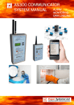
AS200 ALARM SYSTEM
ALARMING
MONITORING
DATA LOGGING
AS200 Wireless Alarm,
Monitoring and Data Logging System
USERS MANUAL
Features
Multi Function Alarm / Data Transmitter
♦ Multi Channel Receiver
♦ Range Increase Transceiver
♦ Internet Access for Alarm Information
♦ Communication Options
♦ Data Capture Capability
♦
Important ► Before operating the system the notice on the third page of this manual must be read.
© Doc No 0602-AS200-004
Leaflet No AS200 Manual
AS200 ALARM SYSTEM
Page 2
Table of Contents
IMPORTANT : THIS PAGE MUST BE READ BEFORE OPERATING ALARM SYSTEM
Page 3
1.0
Overview
Page 4
3.5
Display Indicating Lost
Page 9
2.0
Transmitter AS200TX
Page 4
3.6
Alarm Guard Time
Page 9
2.1
Transmitter Features
Page 4
3.7
Power Fail
Page 9
2.2
Transmitter Inputs
Page 4
3.8
Delete Alarm Memory
Page 9
2.2.1
Temperature Input 1
Page 4
3.9
Volt Free Contact
Page 9
2.2.2
Temperature Input 2
Page 4
3.9.1
Communications Connections
Page 10
2.2.3
Volt Free Contact Input 3
Page 4
3.9.2
Buffer Board
Page 10
2.3
Output
Page 4
4.0
Transceiver
Page 10
2.4
Transmitter Power Failure / Battery Low
Page 5
4.1
Transceiver Overview
Page 10
2.4.1
Battery On Sw / Transmitter Disable
Page 5
5.0
Monitoring & Data Capture Software
Page 11
2.5
Front Panel Description
Page 5
5.1
Overview
Page 11
2.5.1
Setup Switch
Page 5
5.1.2
Connecting a Computer to AS200RX
Page 11
2.5.2
Transmitter Initial Setup
Page 5
5.1.3
Installing Capture Software
Page 11
2.5.2.1
Base Setting
Page 5
5.1.4
Connecting to the AS200RX
Page 11
2.5.2.2
Calibration Reminder
Page 5
5.1.5
Main Screen
Page 11
2.5.2.3
Unit Number Setting
Page 6
5.1.6
Descriptions
Page 12
2.5.2.4
Delay Time Setting
Page 6
5.1.7
Alarms
Page 12
2.5.2.5
High and Low Alarms
Page 6
5.2
Data Analysis Software Overview
Page 12
2.5.3
Quick Setup to change Unit No, Time Delay or High & Page 6
Low Alarms
5.2.1
Installing Data Analysis Software
Page 12
2.5.3.1
Unit Number Setting
Page 6
2.5.3.2
Delay Time Setting
Page 6
2.5.3.3
High & Low Alarms
Page 6
2.6
Automatic Self Test Wireless Link
Page 6
2.7
Check Signal Strength
Page 6
2.8
Calibration for Temperature
Page 6
2.9
AS200TX Simulator
Page 7
3.0
Receiver AS200RX
Page 7
3.1
Receiver Features
Page 7
6.1.2
SIM Card & Signal Strength
Page 14
3.2
Positioning Receiver
Page 7
6.1.3
Initial Setup
Page 14
5.2.2
Opening a Data File
Page 12
5.2.3
Using a Data File
Page 12
5.2.4
Top Screen Displayed Information
Page 12
5.2.5
Column Data
Page 13
5..2.6
Filtering Data
Page 13
5.2.7
Displaying Graphs
Page 13
5.2.8
Printing Data or Graphs
Page 13
6.0
Communications
Page 14
6.1.
COMGSM Dialler Overveiw
Page 14
3.1.2
Arial and Power
Page 7
6.1.4
Arial & Power
Page 14
3.1.3
On / Off & Battery Switch
Page 7
6.1.5
Battery Switch
Page 14
6..1.6
Connection to Computer
Page 14
3.1.4
User KeyKey-Fobs
Page 7
3.2
Connecting a Computer to AS200RX
Page 8
6.1.7
Installing COMGSM Software
Page 14
3.2.1
Set Time / Date & KeyKey-Fob Names
Page 8
6.1.8
Using GSM Software
Page 14
3.2.2
Download Memory
Page 8
6.2
User Number Message Setup
Page 15
3.3
Mute Button
Page 8
6.3
Telephone Outgoing Calls
Page 15
3.3.1
Scroll Button
Page 8
3.3.2
Acknowledger Button
Page 8
3.3.3
Add / Remove Transmitter Button
Page 8
3.4
Power Led
Page 8
3.4.1
Alarm Led
Page 8
3.4.2
Alarm not Acknowledged
3.4.3
Alarm Reactivation Led
Page 9
Communications Sent Led
Page 9
3.4.5
Relay Activated Led
Page 9
Receiver Display / Messages
© Doc No 0602-AS200-004
Enabling COMGSM Unit
Page 16
Connecting the GSM Unit to a Receiver
Page 16
6..6
Alarm Activation
Page 16
6.7
Acknowledging Alarms
Page 16
6.8
Canceling Multiple Alarms
Page 16
6.9
Conventional Speech Dialler Unit
Page 17
7.0
Installation
Page 18
Page 8
3.4.4
3.4.6
6..4
6.5
8.0
Testing System Integrity
Page 19
9.0
Appendix
Page 20
10.0
Test Record Sheet
Page 21
Page 9
AS200 ALARM SYSTEM
Page 3
Important ►THIS PAGE MUST BE READ BEFORE
OPERATING THE ALARM SYSTEM
To maintain a high level of confidence in the complete Alarm System it’s integrity must be tested on a regular basis.
The responsibility rests with the user as to how often the Alarm System is
fully tested. This will probably depend on the value of the samples which
are being kept in their equipment.
All alarm systems are there to assist in the overall protection of your product. Good maintenance of the alarm monitored equipment is the first line
of defence in maintaining the correct operating temperature or environment for your product.
All alarm systems have to be checked on a regular basis. Regular checking
will find any faults that have occurred thus improving the overall integrity.
A test schedule and procedure is shown in Section 8 which is provide as a
minimum. The responsibility for product protected by the alarm system
rests completely with the user. The alarm system must be used only as one
aid in the customers overall procedure for protecting their product.
The alarm system must never be used as the primary alarm to protect
humans or animals.
The Alarm System can only be set up correctly and its operation
understood if the manual is read fully. If there are any points
which are not clear please contact your supplier for assistance.
© Doc No 0602-AS200-004
AS200 ALARM SYSTEM
Page 4
Section 1 ► Overview
•
The AS200 Wireless Alarm, Monitoring and Data Logging
System allows laboratory and hospital equipment to be
alarmed, monitored and data logged such as Liquid Nitrogen, ULT Freezers, Fridges, Freezers and Incubators . The
temperature transmitter range is -200°C to +100°C with
an accuracy of 0.1°C.
2.2 Inputs
The system ensures the safety and continued effectiveness of medicine produce, blood products and samples
at specific refrigeration and freezer temperatures. Due to
the high value of many of these goods, QA programs increasingly require that storage temperatures are to be
verified several times per day and that records be maintained. The AS200 System will meet the alarm, monitoring and logging requirements, offering different levels of
logging software.
Several types of communications can be fitted to the
receiver unit, from a conventional auto-dialler to a GSM
dialler or web enabled facility.
2.1 Features
•
Compact size.
Simple to use.
•
110H x 65W x 27D (mm)
Section 2 ► AS200TX
•
•
•
•
•
•
•
•
•
•
•
•
•
•
•
•
•
Inputs available : Temperature, 44-20mA and Volt Free
Contact.
Temperature range –200°C to
+100°C.
Temperature transmitter resolution 0.1°C.
Temperature transmitter accuracy better than 0.1°C across
the full range.
Front panel display of I/P1,
temperature (or other variable
input used), time delay, unit
number ID and alarm parameters.
Temperature high and low alarms.
Audible and visual indication of an alarm.
Adjustable time delay for temperature alarm. (0 to 90
minutes)
Mains power failure alarm.
Alarm information sent to receiver AS200RX, giving
details of transmitter unit and fault.
Status and alarm indication on transmitter.
Temperature, high & low alarms and delay time data
transmitted every 30 minutes. This increases to every
10 minutes when in alarm. (Increased
(Increased frequency data
transmitters available on request)
request)
System self test.
Volt free contact output available.
Rechargeable battery backup.
Easy calibration procedure / Auto calibration reminder
customer set. Settings ; none, 6 months or 1 year.
Rubber holster for easy installation and positioning.
© Doc No 0602-AS200-004
Traceable calibration for temperature can be carried out
for the AS200TX alarm transmitters.
The Transmitter unit has three inputs labelled I/P1,
I/P2 and I/P3.
I/P3 All the input connectors have screw terminals and are accessible by removing the back cover. To
locate the input connectors remove the rear compartment flap.
2.2.1 Temperature Input (I/P 1)
Temperature input 1 uses a PT1000 probe. The value of
this input is displayed on the front panel when temperature is selected. The input range is +100°C to –200°C
with a instrument accuracy of 0.1°C. This input is usually
used as the main air temperature alarm input..
This input has an adjustable time delay between 0 and
90 minutes.
2.2.2 Temperature Input (I/P 2) (Option)
Temperature input 2 uses a PT1000 probe. The input
range is +100°C to –200°C with a instrument accuracy
of 0.1°C. This input is usually used as an auxiliary input
and is mainly used to measure product temperature. The
time delay for this input mirrors the time delay set for I/
P1.
2.2.3 Volt Free Contact Input (I/P 3) (Option)
Volt free input 3 can be used to monitor any normally
closed contact. This input is normally used as a door
switch monitor.
Normally closed position = No alarm
Normally open = alarm
This input has a fixed time delay of 10 minutes.
2.3 Output (Option)
The Transmitter unit has one relay output. This is in the
normally open position and will go to the normally closed
position in the event of an alarm. Depressing the mute
switch will reset the relay in the alarm condition.
Page 5
AS200 ALARM SYSTEM
2.4 Transmitter Power Fail/Battery Low
If mains power has been removed from the transmitter
unit the system will activate an alarm after a preset 10
minute delay. A signal will be sent to the receiver. The
receiver will indicate the transmitter unit number and AC
off. The display on the transmitter is extinished and the
buzzer does not sound. This is preserve battery life especially useful if the transmitter is used to log data.
If the power is not re-supplied and the unit is left on battery power, a further alarm “Low Bat” will be generated
when the batteries are nearly exhausted.
2.4.1 Battery ON Switch/Transmitter Disable
To locate the battery switch remove the rear compartment flap. The battery On / Off switch is located at the
bottom LHS of the transmitter. To turn the battery ‘ON’
first connect the D.C. power, then place battery switch to
the ‘ON’ position. If the battery switch is not switched on
after the DC supply is connected the display will intermittently flash up Bat, reminding the user that the battery
has not been switched on.
To disable the transmitter turn the battery switch to the
‘OFF’ position and remove the DC supply.
Note : If a transmitter is removed from the system, the
receiver will have require the Add/ Remove transmitters
from system initiated. If this is not done the removed
transmitter will come up as being “lost” at the receiver.
Led's
Alarm Active :Bright red led which flashes when the transmitter is in the alarm condition.
Status :White Led indicating the status of the transmitter.
System ok: - Status Light “ON
ON”
OFF”
ON for 4 seconds and “OFF
OFF for
1 second.
Setup Mode : - Status Light flashes rapidly.
Calibration Mode : - Status Light and Alarm light flashes
rapidly.
Mains Power Fail : - Status Light “OFF
OFF”
OFF for 4 seconds and
“ON
ON”
ON for 1 second. (Note in a power fail condition the
display is switched off to conserve battery life).
In Alarm Condition : - Status Light “ON
ON”
ON for 1 seconds and
“OFF
OFF”
OFF for 1 second. (A full alarm will only be initiated
after delay time has elapsed.)
Unit Number :Red led which is illuminated when the display is indicating the transmitter unit number.
Time Delay : Red led which is illuminated when the display is indicating the transmitter time delay for input 1
and input 2.
Temperature :Red led which is illuminated when the display is indicating the transmitter temperature of input 1.
2.5.1 Setup Switch
The setup switch is located at the top of the transmitter
(Small hole). This will require a end of a paper clip or pen
pushed through the small hole to activate setup the
mode. When in setup mode the white status led will flash
rapidly. If the transmitter is left in setup mode it will return to normal mode after approximately 3 minutes.
2.5.2 Transmitter Initial Setup
The setting of the base, calibration reminder, unit number, time delay and high & low alarms are carried out in
one complete sequence. The sequence must be completed to return the transmitter to its normal operating
condition. The white status led will flash rapidly in setup
mode, this will return to solid for 4 seconds on, 1 second
off in the normal OK condition. If the transmitter is left in
the setup mode it will return to normal mode after approximately 3 minutes.
2.5.2.1 Base Setting
2.5 Front Panel Descriptions.
Switches
Display Switch:
Switch Scrolls the display between Unit Number,
Time Delay and Temperature. This switch is also used in
the setup procedure.
Depress the setup button once, located on the top of the
transmitter. (Small hole) This will require the end of a
paper clip or pen pushed through the small hole.
When in setup mode the white status led will flash rapidly.
Depress the mute button three times and the display will
Mute/Test Switch:
Switch When the audible alarm is sounding it show BASE. Use the up and down arrows to set the base
on the transmitter to the same base as the receiver. (Up
can be muted by depressing the switch for one second.
A signal strength test to the receiver can be carried out by to 16 bases are available, factory default is base 1).
depressing this switch for 10 second. This switch is also Once this has been done press the Mute switch to register this value.
used in the setup procedure.
2.5.2.2 Calibration Reminder Setting
Up/Down Switches:
Switches Scrolls the parameter selected to the Depress the display switch and the Cal reminder mode
will be entered, CAL is displayed. This will now set up the
required value. These switches are also used in the
frequency for CAL being shown on the display. By desetup procedure.
pressing the up and down arrows this can be set for No
CAL, 6 monthly or 12 monthly. Once the required value is
selected depress the mute switch to register this value.
© Doc No 0602-AS200-004
AS200 ALARM SYSTEM
2.5.2.3 Unit Number Setting
Depress the display switch, the unit number led is illuminated. The unit number can be changed by depressing
the up and down arrows. Select a number between 1
and 125. Once the required value is selected, depress
the mute switch to register the value.
Page 6
minutes. Once the required value is selected depress the
mute switch to register the value.
2.5.3.3 High and Low Alarms
Depress the display switch, the temperature led is illuminated, HIAL is displayed momentary. The temperature
high alarm can be changed by depressing the up and
down arrows. Select a number between 100 and –200,
the display will scroll very fast. Once you are near the
2.5.2.4 Delay Time Setting
required value depress the mute switch. Depress the
Depress the display switch, the time delay led is illuminated. The time delay can be changed by depressing the display switch and FINE will be momentarily displayed.
up and down arrows. Select a number between 0 and 90 Depress the up or down arrows to select your actual high
alarm set-point and depress the mute switch to register
minutes. Once the required value is selected, depress
the value.
the mute switch to register the value.
The display switch is again depressed entering the low
alarm mode LOAL is displayed momentary. The tempera2.5.2.5 High and Low Alarms
ture high alarm can be changed by depressing the up and
Depress the display switch, the temperature led is illumidown arrows. Select a number between 100 and –200,
nated, HIAL is displayed momentary. The temperature
the display will scroll very fast. Once you are near the
high alarm can be changed by depressing the up and
required value depress the mute switch. Depress the
down arrows. Select a number between 100 and –200,
display switch and FINE will be momentarily displayed.
the display will scroll very fast. Once you are near the
Depress the up or down arrows to select your actual low
required value depress the mute switch. Depress the
alarm set-point and depress the mute switch to register
display switch and FINE will be momentarily displayed.
the value.
Depress the up or down arrows to select your actual high
The status led will now stop flashing rapidly to indicate
alarm set-point and depress the mute switch to register
that the transmitter is in normal mode.
the value.
The display switch is again depressed entering the low
alarm mode LOAL is displayed momentary. The tempera- 2.6 Automatic Self Test Wireless Link
ture high alarm can be changed by depressing the up and The system will automatically test its communications
between every transmitter and the receiver.
down arrows. Select a number between 100 and –200,
the display will scroll very fast. Once you are near the
If the receiver has not received a signal from a transmitrequired value depress the mute switch. Depress the
ter, a lost alarm will be generated approximately every
display switch and FINE will be momentarily displayed.
Depress the up or down arrows to select your actual low four hours at the receiver until it is acknowledged.
alarm set-point and depress the mute switch to register
2.7 Check Signal Strength.
the value.
The transmitter can be forced to send a test signal to the
The status led will now stop flashing rapidly to indicate
receiver. This is achieved by depressing the Mute/Test
that the transmitter is back in normal mode.
Switch for 10 seconds. No alarms will be activated at the
receiver upon receipt of a test signal. The display will
2.5.3 Quick Setup to change Unit number, Time
show the unit number with the message “Test” to indiDelay or High and Low alarms.
cate a successful transmission. The strength of the sigThe changing of the unit number, time delay and high &
nal will be described as Excellent, Good, Average and
low alarms are carried out in one complete sequence.
The sequence must be completed to return the transmit- Low.
ter to its normal operating condition. The white status led This should be used when installing the system and when
will flash rapidly in setup mode and will return to solid for a transmitter is moved to a new location. The test display
4 seconds on, 1 second off in the normal OK condition. If is removed from the receiver by depressing the Mute
switch on the receiver. Each time a test signal is sent to
the transmitter is left in setup mode it will return to northe receiver it must be removed by depressing the mute
mal mode after approximately 3 minutes.
switch. If this is not carried out the next test signal will
Depress the setup button once, located on the top of the not be registered.
transmitter. (Small hole) This will require the end of a
paper clip or pen pushed through the small hole.
When in setup mode the white status led will flash rapidly.
2.5.3.1 Unit Number Setting
Depress the display switch, the unit number led is illuminated. The unit number can be changed by depressing
the up and down arrows. Select a number between 1
and 125. Once the required value is selected depress
the mute switch to register the value.
2.5.3.2 Delay Time Setting
Depress the display switch, the time delay led is illuminated. The time delay can be changed by depressing the
up and down arrows. Select a number between 0 and 90
© Doc No 0602-AS200-004
2.8 Calibration for Temperature
To locate the calibration switch remove the rear compartment flap. The calibration switch is located to the L.H.S.
above the battery switch. An internal switch disconnects
the temperature probe and a temperature resistance
simulator is attached to simulate the temperature probe.
The simulated probe resistance is set at 1000Ω, which
accurately simulates 0°C. The calibration of the instrument displays a resistance measurement which now can
be adjusted by the up and down switches. The value
required is 999.9 or 0.0 this adjustment is made by the
up and down switches.
Page 7
AS200 ALARM SYSTEM
Once adjusted the accuracy of the instrument can be
checked by switching the calibration switch off. The temperature should now read 0.0. If a AS200TS simulator is
used +50 and –50 can easily be checked. Remove the
simulated probe and return the probe bypass switch to
read the actual probe temperature.
3.2 Positioning Receiver
The choice of receiver site affects the ultimate system
performance; this can be important if transmitters are
positioned at the limit of their range or in buildings were
significant metal is used in their construction (such as
reinforced concrete containing metal rods), or utilising
metal internal partitioning.
The AS200TX is a very stable instrument and will rarely
For maximum range coverage and reliability the receiver
require calibration. It is recommended that the AS200TX should be located in a central position with respect to the
is checked by simulating several temperatures to ensure transmitters. In general, the higher the receiver, the betit is within calibration parameters. This can easily be
ter the range achieved. To avoid screening effects, the
achieved by using the AS200TC temperature simulator.
receiver should be mounted well away from large metal
masses such as metal cabinets. The receiver should be
2.9 AS200TX Simulator
mounted at least 1.5 metres above ground level and
Test temperatures at +50.0°C, 0.0°C and -50.0°C can
positioned at least 3 metres away from mains electrical
be simulated on transmitter input 1 to test the alarm.
panels, electricity cables and sources of high speed
The fob temperature simulator is attached to a connector switching, such as computers, otherwise radiated electriinside the transmitter unit and a temperature probe bycal noise may reduce the receiver sensitivity.
pass switch is thrown. The simulated temperature is
If these instructions are not carried out the Receiver will
selected and will be shown on the display. If this temhave reduced sensitivity and possible future problems
perature is out with the alarm limits it will activate the
can occur like lost transmission of transmitter units.
relevant alarm after the time delay.
The resistance to simulate 0.0C can be supplied with a
Common mistakes when positioning a receiver
traceable calibration certificate. This can be used to
calibrate the AS200TX transmitter.
1. Receiver is positioned in receptions or gate houses
were there is considerable communications equipment.
Section 3 ► AS200RX
3.1 Features
• Compact Size.
• Simple to use.
• 125 Channels, one transmitter
•
•
•
•
•
•
•
•
•
•
•
•
•
•
•
•
per channel.
Additional receivers can be
added to expand system.
Two line LCD display of alarms
giving details of transmitter unit
and fault.
Last 999 alarms stored.
All alarms are time and date
stamped.
key--fob.
Acknowledged by user key
2. Receiver is positioned close to electricity cables beneath the wall surface. Check position of electricity sockets and light switches. Cables from these items will be
run vertically or horizontally. Do not locate the receiver
within 0.5 metre of these cables.
3. Receiver is positioned in a basement.
3.1.2 Arial and Power
The receiver aerial must be screwed into position and DC
power supply connected before operation can proceed.
3.1.3 On / OFF & Battery Switch
The On / Off & Battery switch must be switched ”ON” to
power up the receiver.
Up to four individually named
keykey-fobs available.
Acknowledged alarms gives details of acknowledger and are
time and date stamped.
Add and remove transmitters by a simple press of one button & administrators keykey-fob.
Audible alarm.
Programmable alarm communications window of 10 minutes.
Auxiliary Volt Free Contact : Common, Normally Open, Normally Closed.
Power failure alarm.
Rechargeable battery backup.
Selectable Communications available, internet dialler or
conventional autoauto-dialler.
Internet Access to logged alarm information with internet
dialler option.
10 Selectable Mobiles can be text messaged with detailed
alarm information with the internet dialler option.
3.1.4 User KeyKey-Fobs
The key-fob acknowledges alarms on the receiver. When
acknowledged, the alarm is time and date stamped with
the acknowledgers name. Unacknowledged alarms have
an astrix flashing beside it. Up to four user key-fobs are
available.
Once all alarms have been acknowledged, the relay,
alarm led and communications activated led will be reset.
If any alarms are not acknowledged on the system the
Alarm Not Acknowledged led will be illuminated.
© Doc No 0602-AS200-004
AS200 ALARM SYSTEM
Page 8
Key-fob User 1 is the administrator fob and can be used to add / remove transmitters and delete the alarm memory.
Key-fob user 2 , 3 and 4 can only be used to acknowledge an alarm.
3.2 Connecting a Computer to AS200RX
Load the CD supplied with the receiver and connect the USB cable from the computer to the receiver. New hardware
found screen will appear . Follow on screen instructions to instal drivers.
The drivers are located in the driver section of the CD. Load the software on to the computer and open program
AS200RX following on screen instructions to load time / date and key fob usernames.
3.2.1 Set Time / Date & User Keyfob Names
Load the CD supplied with the receiver and connect the USB cable from the computer to the receiver
Load the AS200RX Setup software on to the computer and open program AS200RX. Click on the
connect button and connected will be displayed once a connection to the receiver has been established.
To set the time and date insert the current time and date then click on Set. Uploaded will be displayed when the new time and date has been installed in the receiver.
To set the key-fob usernames select the key-fob number and insert name then click on set. Uploaded will be displayed when the username has been installed in the receiver. Repeat for all
users key-fobs.
3.2.2 Download Memory
To download alarm log connect the receiver to the computer. Open up the AS200 setup software and click on
Download. You will be asked to give it a file name.
Once the file has been downloaded you can view it by
clicking on view and opening the file.
3.3 Mute Button
When the Mute button is pressed, the alarm sounder is
silenced.
3.3.1 Scroll Button
The Scroll buttons are used to scroll through the
alarms displayed on the LCD. The up scroll button
scrolls the alarm towards alarm No 001. When the
company screen is displayed it will go to the last alarm
then move towards No 001. The down scroll button
scrolls the alarm towards the last alarm. When the
company screen is displayed it will go to the first alarm
then move towards the last alarm.
3.3.2 Acknowledger Button
The Acknowledger button when depressed shows acknowledgement information of acknowledger, time and date.
Scroll to the alarm number where acknowledgement information is required and press the acknowledger button.
3.3.3 Add / Remove Transmitters Button
The Add / Remove button is used when new transmitters are introduced to the system or transmitters are removed
from the system.
To add or remove transmitters depress the Add / Remove button whilst depressing user key-fob 1. The user has 1
hour after this procedure to add new transmitters.
Transmitters which require to be removed from the system must have their power removed and battery switched off
before this procedure is carried out.
3.4 Power Led
The power indicator will be illuminate when mains power is connected
3.4.1 Alarm Led
The alarm indicator will be illuminated when an alarm is active.
3.4.2 Alarm Not Acknowledged Led
If any alarms are not acknowledged on the system the Alarm Not Acknowledged LED will be illuminated.
3.4.3 Alarm Reactivation Led
Will be illuminated when an alarm has been reactivated.
© Doc No 0602-AS200-004
Page 9
AS200 ALARM SYSTEM
3.4.4 Communications Sent Led
The communications sent indicator will be illuminated when communications have been activated.
3.4.5 Relay Activated Led
The relay activated indicator will be illuminated when the relay for the volt free contacts have been activated.
3.4.6 Receiver Display/Messages
The receiver display consists of 2 lines by 16 characters. The last 999 alarms are stored and can be scrolled
through A backlight will illuminate the display when powered. In a power fail condition the backlight will be extinguished to prolong battery life.
The display always shows the last event received. Examples of display messages are as follows :
AV200RX
2401141 Base 1
Power On Display
AV200RX is the product name.
240118 Is the software version
Base 1 is the Receiver address.
COMPANY
34 Units Base 1
NO ALARMS DISPLAY
Company is the Supplier.
34 Units is the total number of Transmitters on
the system.
Base 1 is the Receiver Address.
097 Unit 12 I/P 1
* 15:47 26:08:05
097 is alarm number.
Unit 12 is Transmitter 12.
I/P 1 is Alarm on Input 1.
* Alarm Acknowledgement Status.
15:47 Time alarm was received
26:08:05 Date alarm was received
Note * Flashing indicates alarm not acknowledged
* Solid indicates alarm acknowledged.
098 Unit 38 I/P 2
* 16:47 26:08:05
098 is alarm number.
Unit 38 is Transmitter 38.
I/P 2 is Alarm on Input 2.
* Alarm Acknowledgement Status.
16:47 Time alarm was received
26:08:05 Date alarm was received
If the transmitter has not been switched off the likely cause
is that equipment has been place in the signal path or new
building works etc have interrupted the signal. Move the
transmitter and test. If lost keeps appearing after this action has been taken fit a transceiver between the transmitter and receiver.
3.6 Alarm Guard Time
The alarm guard time is the time allowed once an alarm is
activated at the receiver, to acknowledge an alarm with
the user key-fob, without activating the external communications and volt free contact.
The guard time has two options, no delay or a 10 minutes
delay. This time is set at SW2 on the rear of the receiver.
When this switch is in the ON position the guard time is O
minutes. When this switch is in the OFF position the guard
time is 10 minutes.
3.7 Power Fail
099 Unit 29 I/P 3
* 17:57 26:08:05
101 Unit 17 AC
* 18:57 26:08:05
103 Unit 10 Lost
* 22:11 29:09:05
098 is alarm number.
Unit 38 is Transmitter 38.
I/P 2 is Alarm on Input 2.
* Alarm Acknowledgement Status.
16:47 Time alarm was received
26:08:05 Date alarm was received
101 is alarm number.
Unit 17 is Transmitter 17.
AC is a power fail alarm.
* Alarm Acknowledgement Status.
18:57 Time alarm was received
26:08:05 Date alarm was received
103 is alarm number.
Unit 10 is Transmitter 10.
Lost indicates that the automatic test transmission was not received over a calculated period.
* Alarm Acknowledgement Status.
22:11 Time alarm was received
29:09:05 Date alarm was received
Note Lost indicates a serious or complete transmission problem from a particular transmitter and
should be investigated immediately.
Unit 01 Test
GOOD
Unit 10 is Transmitter 10.
Test indicates a manual test transmission from
the transmitter and gives the percentage signal
received from that transmitter.
When the receiver detects the loss of external AC power,
the sounder is activated, AC Fail is displayed and an alarm
is activated.
3.8 Delete Alarm Memory
It is strongly advised that the alarm memory log is
downloaded and saved to a computer before deletion.
The alarm memory can be completely deleted by the following procedure.
1. Depress Add / Remove button once.
2. Within 10 seconds after depression of Add / Remove
button, press Mute Alarm button once.
3. Depress and hold Acknowledger Button and depress
user key-fob 1 (Administrators Key-Fob).
4. During the depression of Acknowledger Button and KeyFob User 1 the display will flash CAUTION! MEMORY WILL
BE ERASED.
5. Once deleted the display will flash MEMORY ERASED for
approx 5 seconds then the memory record 001 will display
Memory Deleted with the User name, date and time
3.9 Volt Free Contacts
The relay contacts are rated at 2A @ 240Vac.
The relay contacts are for clients own remote alarm connections and are presented on an 3 way screw terminal
block accessible at the rear of the enclosure. They are
3.5 Display Indicating Lost
Indicates that the automatic test transmission was not marked C (Common), NC (Normally Closed) and NO
(Normally Open). They change from this state in an alarm
received over a calculated period. This indicates that
the transmitter has been switched off or the usual path condition. E.g. The Normally Open contact will become
of the signal has been severely interrupted. If the trans- closed.
mitter has been switched off remove it from the receiver with the acknowledgers key-fob and add/remove
button.
AC failure of the receiver and any transceivers on the
system will also be displayed on the screen.
© Doc No 0602-AS200-004
AS200 ALARM SYSTEM
3.9.1 Communications
Page 10
Section 4 ► AS200TR
Once an alarm is received at the receiver and the User
Key-Fob is not depressed within the alarm guard time the 4.1 Overview
following will happen: The transceiver unit is used to
increase the distance between a
With Standard Speech Dialler
transmitter and the receiver, if
The speech dialler will be activated and will send a rerequired. There is no limit to the
corded message to up to four telephone numbers.
number of transceivers that can
The volt free contact will be activated.
be used in the system.
The transceiver is powered by an
external DC supply and has a rechargeable battery fitted as standard. If power fail is detected on
the transceiver an alarm will be
sent to the receiver initiating an
alarm condition.
Battery Switch
12 34
Switch 1 switches the battery ON or OFF. The normal
operational setting for this switch is ON.
Test Switch
Switch 2 switches the test mode ON or OFF. This switch
must be in the OFF position under operational conditions.
Setup Switches
With Internet Communication
The alarm information will be sent to the users password
protected web page. When an alarm is sent to the web
page it will be date and time stamped. The full history of
alarms will be logged on the web page and cannot be
deleted. The full alarm message will then selectively text
messaged, up to a maximum of 10 mobiles or e-mails.
If the User Key-Fob is depressed to acknowledge the
alarm within the guard time no communications will be
activated.
3.9.2 Data Buffer
If a data buffer is fitted to the receiver (internally fitted) it
will store one transmitters data for 170 days. The
amount of memory used by the number of transmitters
on the system is easily calculated by dividing 170 days by
the number of transmitters on the system. E.g. 10 transmitters on the system would allow for 17 days of storage.
The data buffer should only be used as a backup if there
is a failure on the computer collecting the transmitters
data.
© Doc No 0602-AS200-004
See appendix 8 for setup configuration. (Para 8.2)
AS200 ALARM SYSTEM
Page 11
Section 5 ► Monitoring & Data Capture Software
5.1 Overview
• Display and logging of all the information sent from the transmitters.
• Data is updated every 30 minutes from each transmitter, increasing to every 10 minutes when in an alarm con•
•
•
•
dition.
Information sent from each transmitter includes the following :- transmitter number, transmitter serial number,
value I/P1, value I/P2, value I/P3, high alarm set-point, low alarm set-point, delay time and time of last update.
Alarm status of input 1, input 2, input 3, AC power and low battery are displayed.
Data is recorded in a CSV and PSA file. The PSA file is encrypted and can only be decoded and read by our
analysis software. The CSV file can be read in our analysis software or excel. A set of new CSV and PSA files are
generated every day to make record archiving simple.
Standard 25 inputs can be expanded in blocks of 25 up to 125 inputs.
5.1.2 Connecting a Computer to AS200RX
Connect the USB cable from the computer to the receiver. It is assumed that the drivers will be loaded from the initial
installation of the setup software. If the drivers have not been installed consult the AS200 Operating manual and
disc supplied with the receiver.
5.1 3 Installing Capture Software
It is suggested that a new folder is made called Temperature Data or a name of your choice to describe were the
data and Capture software file will be stored. Double click on the AS200 Capture 25 file, prompts will guide the installation. Once installed the program can be accessed from the program bar under the heading Asper.
♦ Note : If the capture software is installed in the desktop folder and not a folder nominated by the user the data
icons will be displayed on the desktop screen.
5.1.4 Connecting to the AS200RX
If the Receiver is connected to the computer the capture software will connect automatically when the program is
started. Connect will be displayed at the bottom LHS of the screen. If the software has not been connected disconnected will be displayed. To connect manually go to File > Connect.
The Capture software must be continually run to capture and store data. If the receiver becomes disconnected from
the computer the system will display “Disconnected”.
♦
Note : If you find that the software does not collect data, this will be displayed by an error file at the first time a
transmitter sends its data. This is caused by older drivers for USB ports on older operating systems. A simple
fix to upgrade drivers and USB port is to install a USB hub and connect it into the existing USB port. A USB hub
is supplied free of charge with the software in case it is required.
5.1.5 Main Screen
The data will collect the following details from each transmitter, transmitter number, transmitter serial number, value
I/P1, value I/P2, value I/P3, high alarm set-point, low alarm set-point, delay time and time of last update. This data
will be collected every 30 minutes, this interval will increase to every 10 minutes when the transmitter is in an alarm
condition.
© Doc No 0602-AS200-004
AS200 ALARM SYSTEM
Page 12
5.1.6 Descriptions
The user can enter descriptions for I/P1, I/P2 and I/P3 for each transmitter. Most transmitters purchased only use
I/P1 and a typical description would be type of equipment or ID or location. E.g. –80 Freezer No 05
5.1.7 Alarms
Alarms are indicated on the screen by the colour off the transmitter monitoring box changing from green to red.
Items monitored are I/P1, I/P2, I/P3, AC connected and battery low.
5.2 Data Analysis Software Overview
• CSV and encoded PSA files can be read.
• Numerical & Graph information easily displayed for any transmitter.
• Easy print facility for data required.
• Filtering of data is possible between specific dates and times.
• Statistical Information of the following is recorded : First Reading; Date and Time, Last Reading; Date and Time,
•
Number of Readings, Maximum Temperature, Minimum Temperature, Average Temperature, Time in High Alarm
and Time in Low Alarm.
The Data Capture software and Data Analysis software come as a package. Each licence allows one capture
software and up to 5 data analysis software programs.
5.2.1 Installing Data Analysis Software
Double click on the AS200 Alarm and Monitoring Data Analysis file, prompts will guide the installation. Once installed the program can be accessed from the program bar under the heading Asper.
5.2.2 Opening a Data File
To open a data file go to File > Open. The files are automatically saved in a date form e.g. 12_08_2006 is data collected on the 12th August 2006. Two files are made for each date a csv and psa. The psa file is encrypted and can
only be viewed in the analysis software.
5.2.3 Using a Data File
Once the required date or dates are opened for analysis, select the transmitter unit number required to be viewed.
This is done by using the mouse to move the “Transmitter Unit” Column numbers up or down. Once the required
transmitter unit is selected data for this unit is displayed.
5.2.4 Top Screen Displayed Information
Information at the top of the screen is displayed for the selected transmitter. The information is Serial Number, Descriptions if entered into the capture screen, First Reading, Last Reading, Number of Readings, Max Temp, Min Temp
and Average Temp.
© Doc No 0602-AS200-004
AS200 ALARM SYSTEM
Page 13
5.2.5 Column Data
The data in the columns gives easy access to the following :Date, Time, Temperature input 1, Temperature Input 2, Door Switch I/P3, AC Power, Battery Condition, High Alarm
Set-point, Low Alarm Set-point and Delay Time.
5.2.6 Filtering Data
Data can be filtered by ticking the filter box and selecting a start date and time and end date and time. Once this has
been done click on the filter button.
5.2.7 Displaying Graphs
A graph of the current data can be displayed by clicking on the Graph Tab at the bottom LHS of the screen. To return
to the data display, click on the Data Tab at the bottom LHS of the screen.
5.2.8 Printing Data or Graphs
To print out the data selected go to File > Print. To print out a graph of the data selected, display the graph as described in para 2.7 and go to File > Print.
© Doc No 0602-AS200-004
AS200 ALARM SYSTEM
Page 14
Section 6 ► Communications
6.1 COMGSM Dialler
Overview
The GSM Dialler will dial up to 5 telephone numbers or emails when an alarm is activated. Targeted personnel for a particular piece of equipment will be contacted in the
event of an alarm. The targeted message will contain the alarming transmitter unit
number and a generic description. No telephone line is required so installation of this
device can be carried out in remote locations.
6.1.2 SIM Card & Signal Strength
An 02 pay as you go sim card is provided with approximately £10 worth of credit on it.
This has been provided primarily to get the system commissioned on site. The user
can top up this sim card or opt for a contract sim card of their choice. As the GSM unit
is usually connected to give information for an alarm it is highly recommend that the
user replaces the pay as you go sim to a monthly contract sim. The O2 network has
been chosen as it has a very good network coverage in the UK. The final location the
COMGSM unit site may require another network for good signal strength.
Once power has been connected to the COMGSM Unit, the system will sound a bleeping tone and the status and function leds will be red. The status and function leds will
turn green within 30 seconds of applying power. When the unit picks up a satisfactory
network signal the bleeping will stop. If the signal strength is lost to the COMGSM unit
a bleeping tone will sound. This gives audible indication to the user that the unit will
not respond to an alarm, as the unit has not got adequate signal strength from the network being used. If this happens the COMGSM unit should be located in an area where a good network signal is achievable or change the sim
card to another network with a good signal strength in the area required.
To check signal strength and if any alarms are active on the GSM unit, send the message Q to the GSM’s sim’s telephone number.
6.13 Initial Setup
All Connections and layouts can be found in Figure 1, 2, 3, 4 and 5.
6.1.4 Arial & Power
Connect the Arial and 12V DC Power Supply to the Unit.
6.1.5 Battery Switch
Switch battery ON, remove rear flap battery switc located near middle at bottom. Yellow in colour.
6.1.6 Connection to Computer
Connect the serial cable between the GSM unit and serial port 1 of a computer, using the cable supplied. If your
computer does not have a serial port a USB to serial port adaptor (USB to RS232 connector) is supplied with the
COMGSM unit.
6.1.7 Installing COMGSM Software
Install the COMGSM SETUP file on to your computer. This file is found on the CD supplied in the AS200 COMGSM
folder. Follow screen prompts to install the software.
6.1.8 Using GSM Software
The COMGSM unit must be placed into the configuration mode before any changes can be made to the unit. This is
achieved by toggling the large button marked EDIT SETTINGS. In the configuration mode the function led on the front
panel of the COMGSM unit will turn red.
To return the COMGSM unit back to normal alarm mode click on the large button marked ENABLE GSM UNIT. In this
mode the function led on the front panel will turn green.
When the view buttons are depressed e.g. View Selected, View Contacts etc, the information displayed in the black
top screen is the stored details taken from the COMGSM Dialler. Details entered into the Setup menu on the computer will not become active in the COMGSM dialler unit until the relevant “Update” buttons are depressed.
It is recommended that the relevant “View” buttons are depressed before the GSM dialler is disconnected from the
computer setup. This is to check the correct details are entered into the COMGSM dialler unit. Once the COMGSM
unit is connected to a receiver a full test to check the dialler unit is working correctly must be carried out.
© Doc No 0602-AS200-004
AS200 ALARM SYSTEM
Page 15
6.2 User Number Message Setup
6.2.1 Entering Contact Phone Numbers or Email address
This is achieved in the User Number Message setup box. Enter telephone numbers or email address in the Contact
Numbers 1 to 5. To update this information into the COMGSM dialler click on the “Update All Contacts” button.
When entering a number +44 must be used in front of the number and the 0 must be removed.
E.g. Mobile number 07756452398 would be entered as +447756452398, Land Line 0131 645 3976 would be
entered as +441316453976
Land lines will receive the sms message through a BT service which converts the sms message to a synthesised
voice message. Email address entered will receive a message containing the mobile number which has acknowledged the alarm message. This is useful record of who acknowledged the alarm call. The email address is not used
to send an alarm.
6.2.2 Entering Outgoing Message
Enter a outgoing message in the outgoing message box. To update this information into the COMGSM dialler click on
the “Update Outgoing Message” button. When a message is sent it will contain this message and the transmitter
unit number which activated the alarm.
6.2.3 E Mail Gateway
The email gateway is a number which is used to convert an sms message to an email. This has been setup as default and will only required to be changed if the user wishes to use another provider. The provider of this service is
sent on every email and at present they do not charge for this service.
6.2.4 View Settings
Clicking on this button will display in the top black screen the email gateway and outgoing message that are programmed into the COMGSM Dialler.
6.2.5 View Contacts
Clicking on this button will display in the top black screen the contact numbers and email address that are programmed into the COMGSM Dialler.
6.3 Telephone Outgoing Calls
6.3.1 Telephone Outgoing Call Sequence
Select the transmitter number required. Select the outgoing
sequence for this transmitter for the first call through to the
fifth. If a outgoing number is not required select 0.
E.g. If transmitter number 02 is selected and the outgoing
sequence is 1st : 3, 2nd : 2, 3rd : 1, 4th : 4 and 5th : 5. This
would mean the first number phoned would be contact number 3, the second number phoned would be 2, the third number phoned would be 1 etc.
6.3.2 Update Selected
Clicking on this button will update the selected transmitter
number outgoing call sequence to the COMGSM unit.
6.3.3 Update All Sequences
Clicking on this button will update all the transmitter numbers sequences to the COMGSM Dialler. An “Updating All
Sequences” tool bar will be displayed on the progress of this
update which can take approximately 90 seconds.
6.3.4 View Selected
Clicking on this button will display the telephone number sequence for the transmitter selected in the COMGSM unit,
this will be displayed in the top black screen.
6.3.5 View All
Clicking on this button will display all the telephone number sequences for all the transmitters in the COMGSM unit,
this will be displayed in the black screen.
6.3.6 Clear All
Clicking on this button will clear the memory in the COMGSM Dialler unit. All transmitter outgoing call sequences and
the user number setup will be deleted.
6.3.7 Store Sequences / Store Settings on PC
Clicking on this button will save the data entered into the COMGSM setup menu into a file on the PC. Please do this
before closing the program to save your data.
© Doc No 0602-AS200-004
AS200 ALARM SYSTEM
Page 16
6.4 Enabling COMGSM Unit
Once all settings have been entered and checked the COMGSM unit must be taken out of the configuration mode to
enable alarm mode. Click on the “Enable GSM Unit” button, the function led on the COMGSM unit front panel will
change from red to green. Note :- This can take up to 30 seconds.
6.4.1 Testing an Alarm Call From COMGSM Unit
The COMGSM unit must be in the enable alarm mode e.g. function led green, Select the transmitter number and I/p
required and click on the test alert button.
The unit will now dial the required sequence for the selected unit. The test alert transmitter must be set up previously in the configuration mode. E.g. If unit 7 is selected for testing, unit number 7 must have its call sequence setup
to work.
6.5. Connecting the GSM unit to the Receiver
Make sure the function led is green. Connect the cable supplied between the Rx connection of the COMGSM unit,
Fig 3 and connecter in rear of the receiver.
6.6 Alarm Activation
When an alarm is received at the AS200RX receiver it will trigger the GSM unit. This could be delayed for up to 10
minutes depending on the guard time setting at the receiver. If the receiver is acknowledged within the guard time
the GSM unit will not be activated.
Once the GSM unit is triggered the status led will start flashing red, after approximately 40 seconds the first number
on the telephone list off the transmitter that has activated the alarm will be telephoned. If the alarm is not acknowledged the second number on the list will be telephoned and so on up to contact number 5. The time between calls
is approximately 90 seconds. If no person has acknowledged the alarm the telephone sequence will be repeated.
This will take place approximately 10 to 15 minutes after the call to contact number 5.
Only approximate times can be given between calls as it depends on the network used and how busy it is.
6.7 Acknowledging Alarms
To acknowledging an alarm a mobile phone can only be used. When an alarm message is received at the mobile
phone, reply to the call with the unit number alarming. If this is successful no more calls will be phoned and a second message will be received with the mobile number of the person who acknowledged the call. This acknowledgement message will go to all mobile telephone numbers that have been set up in the call sequence. If an email is in
the contact list the acknowledgers telephone number will be sent to the email address for reference purposes.
E.G. Alarm from Transmitter number 9, reply to alarm message with 09 then send., Alarm from transmitter number
36, reply to alarm message with 36 then send.
6.8 Cancelling Multiple Alarms
If multiple alarms are received at the GSM unit e.g. an AC power fail so all transmitters are sending in power fail
alarms. In this case the GSM unit will send out each alarm until acknowledged, which could be annoying and take a
considerable mount of time depending how many transmitters are on the system.
The GSM unit can be reset of all its alarms by sending the message reset in lower case to the GSM’s Sim’s telephone number.
RS232 PC / RX CONNECTION
© Doc No 0602-AS200-004
AS200 ALARM SYSTEM
Page 17
6.9 Conventional Speech Dialler Unit
General Note : It is always recommended to have installed a direct telephone line for this device.
If simpler communications are required a speech dialler unit can be fitted to the
receiver.
Power for the speech dialler and alarm trigger is obtained from the receiver. This
ensures that, even during a mains power cut, the equipment will still detect an
alarm condition and dial out.
The Speech Dialler Unit accepts one input from the receiver, which causes corresponding messages (A,) to be sent
out to pre-arranged telephone numbers.
Telephone Numbers: The Speech Dialler Unit will dial up to a maximum of four different telephone numbers and play
its message. The numbers may be up to 16 digits long and are simply programmed using the text display and keypad
on the unit.
Messages: The Speech Dialler Unit has a built-in microphone and speaker so that phrases can be recorded and replayed directly from the unit. When the out-going call is answered by the remote telephone the speech dialler unit
plays a common phrase (0) plus one of the specific alarm messages (phrase A). Phrase 0 normally states the location
of the establishment or building and phrases A relate to the location of the Receiver. Each phrase can be up to 20
seconds long giving a total possible message length of 40 seconds (messages 0 + A).
Acknowledgement : On receiving a call from the Speech Dialler Unit the person answering acknowledges it by pressing the number [8] on their telephone keypad, this prevents further calls being initiated. The speech dialler unit may
be programmed to stop dialling after the first call has been acknowledged or when two or three have been acknowledged, as required.
If the message is not acknowledged then it is repeated three times, after which the dialler abandons the call. It then
dials the next number. This procedure is repeated three times in sequence for all four telephone numbers. If no acknowledgement has been received then the dialler shuts down.
FOR FULL UP TO DATE INFORMATION ON HOW TO SET UP AND USE THE AUTODIALLER PLEASE READ ENCLOSED BOOKLET SD1+ SPEECH DIALLER / OPERATORS MANUAL. (Only
(Only Supplied if this option is selected)
lected)
The Speech Dialler unit is manufactured by an independent company from the alarm system. Its operation and warranty guarantee are that of the manufacturing company.
© Doc No 0602-AS200-004
AS200 ALARM SYSTEM
Page 18
Section 7 ► Installation
Purpose: The information given in this section will enable a the alarm system to be installed correctly with no
expert help. If the system has already been installed and
commissioned by the supplier then this section can be
ignored. Most of the information required to operate the
system has already been covered in previous sections but
is summarised here in relevant stages for clarity during
installation.
Receiver
STAGE 1
Selecting the Alarm Receiver Site.
Site
The choice of receiver site affects the ultimate system
performance; this can be important if transmitters are
positioned at the limit of their range or in buildings were
significant metal is used in their construction (such as
reinforced concrete containing metal rods), or utilising
metal internal partitioning.
For maximum range coverage the receiver should be
located in a central position with respect to the transmitters. In general, the higher the receiver, the better the
range achieved. To avoid screening effects, the receiver
should be mounted well away from large metal masses
such as metal cabinets. The receiver should be mounted
at least 1.5 metres above ground level and positioned at
least 3 metres away from mains electrical panels and
sources of high speed switching, such as computers,
otherwise radiated electrical noise may reduce the receiver sensitivity.
The receiver requires to be sited near to a single 13A
power outlet and also a standard telephone socket if the
communication facility is to be used.
Transmitters
STAGE 6
Selecting the Alarm Transmitter Site
There is less choice in sighting transmitters, as they must
normally be mounted close to the equipment being monitored.
To minimise shielding effects, the transmitter should be
positioned at the top of equipment to be monitored if
possible, with the wire aerial stub standing above the top
surface of the equipment. This will allow the aerial to
radiate freely in all directions when a signal is transmitted
and ensure maximum range.
The normal operating range of the transmitter is about
100 metres. In practice, depending on the construction
materials of the building, this distance can be larger or
smaller. Once the site has been chosen use the eyelets
and self-adhesive hooks to hang the transmitter in place.
STAGE 7
Inserting the probe into the equipment.
As the probe wire is made out of PTFE covered wire it is
very thin and strong and can normally be passed through
the door gasket of freezers or top inserts of liquid nitrogen equipment without any problem and secured with the
supplied cable ties and bases. In this case, it is not necessary to disconnect the probe wires from the terminal
block located inside the transmitter.
Freezers / Incubators
Once the transmitter is mounted, the probe has to be
inserted into the equipment. This can be done in two
ways:
a) Disconnect the probe wire from the input terminal
block inside transmitter box and pass this wire from the
STAGE 2
inside through any existing probe holes in the freezer,
Setting up Unit Base
Up to 16 individual receivers can be used on one system then reconnect probe wire to the terminal block in the
transmitter unit. In many cases the probe entry into the
giving up to 2048 individual channels. The transmitters
freezer will be frozen solid, making it impossible to fit the
and receivers have to be configured to activate the releprobe in this way until a total defrost has taken place.
vant receiver base unit. The receiver will be factory set
for base No 01. As one standard receiver gives up to 126 b) As the probe wire is made out of PTFE- covered wire it
channels most clients will not require any additional set- is very thin and strong and can normally be passed
up. If additional receivers are used the receiver base can through the door gasket without any problem and secured with the supplied cable ties and bases. In this
be configured on the rear of the receiver. (See Para 3.6
case, it is not necessary to disconnect the probe wires
for details)
from the terminal block.
Allow 30 minutes for the probe to reach the cabinet temSTAGE 3
perature
Setting up Time Guard
The time guard delay allows staff that are present to reset LN2
the receiver thus avoiding any unnecessary alarm phone Employ safety procedures before proceeding e.g. correct
gloves and full-face protection.
calls.
As the probe wire is made out of PTFE covered wire it is
The time delay switch is located at the rear of the revery thin and strong and can be passed through the top
ceiver. (See Para 3.7 for details)
inserts of liquid nitrogen equipment without any problem.
Once the desired depth for the probe is established loop
STAGE 4
the probe wire round the dewar handle and secure with
Enabling Battery.
cable ties.
The battery enable switch should be switched on. (See
Para 3.1.3 for details)
Stage 8
Plug in three-pin transformer into 240V mains and switch
STAGE 5
on battery
Mounting.
Mount unit on wall with single screw, plug in three-pin
transformer into 240V mains socket and connect commu- STAGE 9
Set required Base and Cal Details.
nications option to telephone socket.
(See Para 2.5.2 for details)
© Doc No 0602-AS200-004
Page 19
AS200 ALARM SYSTEM
STAGE 10
Set required Unit No, Delay Time and High & Low Alarms
(See Para 2.5.2.3 for details)
ter on a full alarm. Do this by simulating an alarm on an
input, checking all communications are working.
Every Three Months
Stage 11
Depress the test button.
Depress the test button on the alarm transmitter for 10
seconds. The display on the receiver will give information
of unit number tested.
Stage 12
Test
Test all alarm transmitters to make sure the receiver has
logged on the relevant transmitter unit.
N.B. If the receiver is not triggered move transmitter to a
more suitable location or install a transceiver.
Stage 13
Communications
Connect relevant communications selected.
(See Section 5 for details)
Section 8 ► Testing System Integrity
Check the entire system. Do this by simulating an alarm
on the input of each transmitter, checking all communications are working
Main Cause of Faults
1. Alarm equipment is switched off at mains.
Action: Do not ignore AC Fail alarms at the receiver and
carry out weekly check.
2. Communications equipment is setset-up wrongly or company/hospital telephone exchange has blocked telephone line for certain types of calls.
Action: Check full communications on a regular bases. A
company can change the status of a telephone line at its
exchange to have several blocks on it.
3. Persistent alarms from a faulty piece of equipment,
are ignored.
The system testing is only a recommended minimum; it is Action: Switch off Alarm Transmitter on the faulty piece of
up to the customer to decide how important their samequipment until it has been repaired. Remove the transples are and the frequency of testing required.
mitter unit from the receiver.
Transmission of signal
The system automatically tests transmission between
each transmitter and the receiver. If the receiver does
not receive a test transmission it will alarm at the receiver
as “Lost” giving the transmitter unit number approximately every four hours. To stop the alarming of a lost
transmitter, the transmitter must be removed from the
receiver.
A manual test signal can be sent by depressing the test
button for between eight and twelve seconds on the
transmitters. The receiver will indicate the unit number
with the message “Test”; no alarms will be activated on a
test signal.
Testing Inputs
The only way to completely test the system is by simulating a real fault on an input. Example : If it was a temperature input, the probe would be warmed up and after the
time delay an alarm signal would be sent to the receiver.
If communications were fitted the relevant action would
be processed.
Recommended Minimum
Each Week
Alarm Transmitters
Check white status led is illuminated.
If white led is ‘OFF’ check power has not been switched
off. If mains power is ‘ON’, unit is faulty and must be
returned for repair.
Receiver
Check blue power led is illuminated. If this light is ‘OFF’
check mains power has not been switched off. If power is
on, unit is faulty and must be returned for repair.
Each Month
In addition to the weekly check, test at least one transmit-
© Doc No 0602-AS200-004
AS200 ALARM SYSTEM
Page 20
Section 9 ► Appendix
8.1 Receiver Base Settings Setup
BASE
Sw1
Sw2
Sw 3
Sw
4
0
OFF
OFF
OFF
OFF
1
ON
OFF
OFF
OFF
2
OFF
ON
OFF
OFF
3
ON
ON
OFF
OFF
4
OFF
OFF
ON
OFF
5
ON
OFF
ON
OFF
6
OFF
ON
ON
OFF
7
ON
ON
ON
OFF
8
OFF
OFF
OFF
ON
9
ON
OFF
OFF
ON
10
OFF
ON
OFF
ON
11
ON
ON
OFF
ON
12
OFF
OFF
ON
ON
13
ON
OFF
ON
ON
14
OFF
ON
ON
ON
15
ON
ON
ON
ON
1 23 4
8.2 Transceiver Setup Switches
TRANCEIVER
RECEIVES
BASE
TRANSCEIVER
TRANSMITS
BASE
Battery
Sw1
Test
Sw2
Sw
3
Sw
4
Sw
5
Sw
6
ANY
SAME
Battery
OFF
ON
ON
ON
ON
2
1
Battery
OFF
ON
ON
ON
OFF
3
2
Battery
OFF
ON
ON
OFF
ON
4
3
Battery
OFF
ON
ON
OFF
OFF
5
4
Battery
OFF
ON
OFF
ON
ON
6
5
Battery
OFF
ON
OFF
ON
OFF
7
6
Battery
OFF
ON
OFF
OFF
ON
8
7
Battery
OFF
ON
OFF
OFF
OFF
ANY
SAME
Battery
OFF
OFF
ON
ON
ON
3
1
Battery
OFF
OFF
ON
ON
OFF
4
2
Battery
OFF
OFF
ON
OFF
ON
5
3
Battery
OFF
OFF
ON
OFF
OFF
6
4
Battery
OFF
OFF
OFF
ON
ON
7
5
Battery
OFF
OFF
OFF
ON
OFF
8
6
Battery
OFF
OFF
OFF
OFF
ON
9
7
Battery
OFF
OFF
OFF
OFF
OFF
© Doc No 0602-AS200-004
Examples :
1. Transmitter at Base 1 (Default Setting)
require to go through one Transceiver to a
Receiver at Base 1.
Set Transceiver to [transceiver receives any
base] [transceiver receivers any base] Sw3Sw3ON, Sw4Sw4-ON, Sw5Sw5-ON, Sw6Sw6-ON
2. Transmitter to go through two transponders
to reach a Receiver set at Base 1.
Change the base on the Transmitter to Base 3
Appendix 5.
Set the first Transceiver to [transceiver receives base 3] [transceiver transmits base 2]
Sw3Sw3- ON, Sw4Sw4-ON, Sw5Sw5-OFF, Sw6Sw6-ON.
Set the second Transceiver to [transceiver
receives base 2] [transceiver transmits base
1] Sw3Sw3- ON, Sw4Sw4-ON, Sw5Sw5-ON, Sw6Sw6-OFF.
3. Transmitter to go through three transponders to reach a Receiver set at Base 1.
Change the base on the Transmitter to Base 4
Appendix 5.
Set the first Transceiver to [transceiver receives base 4] [transceiver transmits base 3]
Sw3Sw3- ON, Sw4Sw4-ON, Sw5Sw5-OFF, Sw6Sw6-OFF.
Set the second Transceiver to [transceiver
receives base 3] [transceiver transmits base
2] Sw3Sw3- ON, Sw4Sw4-ON, Sw5Sw5-OFF, Sw6Sw6-ON.
Set the third Transceiver to [transceiver receives base 2] [transceiver transmits base 1]
Sw3Sw3-ON, Sw4Sw4-ON, Sw5Sw5-ON, Sw6Sw6-OFF.
Page 21
AS200 ALARM SYSTEM
Section 10 ► Test Record Sheet
Tx No
Location
© Doc No 0602-AS200-004
Please Photocopy
DATE
TX ON / OFF
Test Record