1
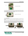
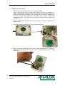
MEC
User Manual
Analox Ltd
15 Ellerbeck Court, Stokesley Business Park
North Yorkshire, TS9 5PT, UK
T: +44 (0)1642 711400 F: +44 (0)1642 713900
W: www.analox.net E: [email protected]
MEC User Manual
List of Contents
1
2
Safety information ..............................................................................................................6
About the MEC...................................................................................................................7
2.1 MEC variants available ..................................................................................................7
3
Installation ..........................................................................................................................8
3.1 Physical mounting..........................................................................................................8
3.2 Gas connections ............................................................................................................9
3.3 Electrical connections (External) .................................................................................10
3.4 Electrical connections (Internal) ..................................................................................10
4
Operation .........................................................................................................................11
5
Oxygen cell replacement .................................................................................................12
6
General care ....................................................................................................................14
7
Calibration ........................................................................................................................15
8
Specification.....................................................................................................................16
9
Warranty Information .......................................................................................................17
10 Disposal ...........................................................................................................................18
Document Ref: MEC-800-00 - March 2011
Page 4
MEC User Manual
Document Ref: MEC-800-00 - March 2011
Page 5
MEC User Manual
1
Safety information
WARNING: Read the safety information fully before using the Analox MEC.
Electrochemical oxygen sensor
The oxygen sensor used in MEC Oxygen variant is an electrochemical sensor which contains
toxic compounds. Under normal conditions the sensor will be safely sealed. To prevent
leakage, the unit must not be exposed to temperatures outside the specified range, or be
exposed to organic vapours, which may cause physical damage to the body of the sensor.
The unit must not be stored in areas containing organic solvents or in flammable liquid stores.
When the life of the sensor has expired or it is leaking or otherwise damaged it must be
disposed of safely in accordance with local regulations.
The sensor contains an acidic electrolyte which is hazardous. In the event of an accident,
use the following first aid procedures
Body Part
Skin
Effect
Contact could result in a chemical burn.
Persons with pre-existing skin disorders
may be more susceptible to the effects
of the substance.
Ingestion
Eye
Corrosive. May cause sore throat,
abdominal pain, nausea, and severe
burns of the mouth, throat, and
stomach, and may be fatal.
Persons with pre-existing eye problems
may be more susceptible to the effects
of the substance.
First Aid Procedures
Immediately flush the skin thoroughly with
water for at least 15 minutes.
Remove contaminated clothing and wash
before re-use.
Obtain medical advice if continued irritation.
If swallowed DO NOT INDUCE VOMITING.
Wash out mouth thoroughly with water and
give plenty of water to drink.
Obtain medical advice immediately
Irrigate thoroughly with water for at least 15
minutes.
Obtain medical advice immediately.
Corrosive. May cause redness, pain,
blurred vision, and eye burns.
Inhalation
Contact can result in the permanent
loss of sight.
Persons with pre-existing impaired
respiratory function may be more
susceptible to the effects of the
substance.
Remove to fresh air.
Rest and keep warm.
Obtain medical advice if applicable.
Inhalation is not an expected hazard
unless heated to high temperatures.
Mist or vapour inhalation can cause
irritation to the nose, throat, and upper
respiratory tract.
Document Ref: MEC-800-00 - March 2011
Page 6
MEC User Manual
2
About the MEC
The Analox MEC is a small, robust sensor module housed in an IP65 enclosure.
An integral pressure sensor provides compensation for the effects of atmospheric pressure.
Digital communication via RS485 permits mounting the sensor up to 500m from the
monitoring equipment.
The Analox MEC allows for easy replacement of sensor cells.
This manual details the use of the Analox MEC with the Analox SDA.
2.1
MEC variants available
The Analox MEC is available in the variants shown in Table 1 below:
Gas
Oxygen
Oxygen
Range
0 to 100%
0 to 3000mBar
In / out of chamber
Outside chamber
In chamber
Table 1
Part Number
MECO2ABB
MECO2AABP
Document Ref: MEC-800-00 - March 2011
Page 7
MEC User Manual
3
Installation
3.1
Physical mounting
The sensor is housed in an IP65 ABS box with integrated mounting holes. The instrument
should be screwed to a suitable surface using the two mounting holes. The drill drawing for
mounting the enclosure is shown in Figure 1 below.
Dimensions: mm
Figure 1 – Mounting drill drawing
The enclosure lid holes are located in the top left and bottom right of the enclosure. The
enclosure lid screws are captive screws.
The mounting holes of the enclosure are located at the top right and bottom left of the
enclosure. A 4mm hole is pre-drilled at these corners that will accept an M4 screw thread. For
the initial installation the enclosure lid should be removed to access the mounting hole
chambers. The mounting screws are fitted in to these and the enclosure can then be secured
to a suitable surface using either tapped holes or nuts. The maximum allowable diameter of
the screw head that can be fitted in to the mounting hole chambers is 6.5mm.
Document Ref: MEC-800-00 - March 2011
Page 8
MEC User Manual
Mounting hole chambers
In the lid at the mounting hole corners there are 4mm access holes predrilled to allow the
mounting screws to be accessed. Once mounted, this enables the MEC to be removed from
its mounting position without needing to remove the enclosure lid. The mounting screws will
then remain captive as long as the lid remains fitted.
Mounting screw access holes
3.2
Gas connections
The sensor may either monitor gas in the surrounding atmosphere or a flow adapter can be
inserted into the gas port inlet to allow monitoring of pumped sample gas from a remote
location.
When used to monitor a pumped sample, Analox recommend that a short length (100 to
300mm) of tubing should be attached to the flow adapter exhaust. Care should be taken to
ensure that the sample flow rate is within specification (0.2 to 1.0 litres/minute) and that the
exhaust line is not restricted, otherwise gas pressure within the sensor may be increased,
resulting in false, elevated O2 readings or damage to the cell.
Monitoring local atmosphere
Monitoring a remote atmosphere via a
sample line
Document Ref: MEC-800-00 - March 2011
Page 9
MEC User Manual
3.3
Electrical connections (External)
Electrical connections with the sensor are made via a short screened cable. The cable screen
is made off into a green/yellow wire terminated with an M4 ring terminal. This wire is unterminated inside the MEC enclosure.
TERMINAL
1
5
4
2
3
CORE
COLOUR
Red
Blue
Blue
Yellow
Green
Green/Yellow
SIGNAL
DETAILS
+SUPPLY
-SUPPLY
RS485 reference
RS485A
RS485B
Earth
Table 2
Power Supply
4.5 to 5.5V DC
Used for 3-wire connection
RS485 communications
Screen
5 4 3 2 1
Use of the screen will depend on the particular installation. It is best connected to a clean
Earth to form a shield around the sensor cable. Note that it is not recommended for the
screen to be connected to the negative supply line.
3.4
Electrical connections (Internal)
The electrical connections made to the internal electronics are made via clamp terminals. It is
important to ensure that each core or the cable is connected to the correct terminal. Shown
below are the correct electrical connections for the power/comms and Oxygen cell.
Document Ref: MEC-800-00 - March 2011
Page 10
MEC User Manual
4
Operation
The MEC connects to the sensor port of the SDA as shown below.
The 5-way terminal block is connected to the SENSOR socket and the Screen should be
connected to the earth stud of the of the SDA enclosure.
Once the MEC and SDA are connected communication between them will automatically be
established.
For further details of operation of the MEC with the SDA refer to the SDA user manual (XK0801).
Document Ref: MEC-800-00 - March 2011
Page 11
MEC User Manual
5
Oxygen cell replacement
1. Replacement part number for your cell is: 9100-9212-9HM
When a replacement cell is received check that the sensor has not leaked. The
sensors are themselves sealed and do not under normal circumstances present a
health hazard however if leakage of the electrolyte has occurred use rubber gloves
and wear chemical splash goggles to handle and clean up. Rinse contaminated
surfaces with water. If anybody comes into contact with the electrolyte, please refer
to Section 1.
2. Ensure all electrical connection between the MEC and monitor equipment are
disconnected.
3. Loosen the corner screws of the enclosure and remove the lid.
4. Using a terminal screwdriver push down the clamp release button to release the
clamp and gently pull the cell wire from the clamp. Repeat this for both the red and
black wires.
Document Ref: MEC-800-00 - March 2011
Page 12
MEC User Manual
5. Unscrew the green lock ring from the chimney of the cell housing and remove from
the enclosure lid.
6. Fit the new cell in to the enclosure lid and secure in place using the lock ring.
7. Using a terminal screwdriver push down the clamp release button to release the
clamp. Push the ferrule of the cell wire in to the clamp and remove the screwdriver
from the clamp release button. Gently pull on the wire to ensure that the wire is held
by the clamp. Repeat this for both the red and black wires, taking note of the correct
polarity as shown below.
Black (-ve)
Red (+ve)
8. Refit the enclosure lid in place and secure in place using the corner screws.
9. Following an Oxygen cell replacement a full calibration MUST be performed. For
further details of calibration of the MEC refer to the SDA user manual (XK0-801).
Document Ref: MEC-800-00 - March 2011
Page 13
MEC User Manual
6
General care
Although designed to be water resistant the MEC should not be intentionally immersed in
liquid or left outside unprotected.
To clean the MEC use a damp soft cloth.
Document Ref: MEC-800-00 - March 2011
Page 14
MEC User Manual
7
Calibration
The calibration of the MEC is performed using the user interface of the SDA. For details of
calibration procedures refer to the SDA user manual (XK0-801).
Document Ref: MEC-800-00 - March 2011
Page 15
MEC User Manual
8
Specification
These units comply with the requirements of DNV for use in commercial diving to a depth of
350m and across the following variations in environmental conditions.
Sensor range (Atmospheric pressure)
Sensor range (Hyperbaric)
Temperature range
Ambient pressure
Humidity
Accuracy
Supply voltage
Data output
Enclosure dimensions (H x W x D)
Remote sensor gas flow rate
0 to 100%
0 to 3000mBar
-5°C to 55°C (23°F to 131°F )
600mbar to 1400mbar (525.0mmHg to
975.1mmHg)
0 to 99% non-condensing
The sensor error is less than 350ppm plus 1% of
the sensor reading at constant temperature. The
variation with temperature is less than 0.15% of
reading /°C.
4.5V to 5.5V dc
RS485 using Analox protocol
65 x 50 x 35 mm
0.2 to 1.0 litres/minute
Document Ref: MEC-800-00 - March 2011
Page 16
MEC User Manual
9
Warranty Information
We provide the following Warranties for the MEC:
A 1 year electronics warranty.
A 2 year graded sensor warranty.
In both cases the warranty period runs from the date of our invoice.
We warrant that the equipment will be free from defects in workmanship and materials.
The warranty does not extend to and we will not be liable for defects caused by the effects of
normal wear and tear, erosion, corrosion, fire, explosion, misuse, use in any context or
application for which the equipment is not designed or recommended, or unauthorised
modification.
Following a valid warranty claim in accordance with the above, the equipment, upon return to
us, would be repaired or replaced without cost or charge but in our discretion we may elect
instead to provide to you which ever is the lesser of the cost of replacement or a refund of net
purchase price paid as per our Invoice on initial purchase from us. We shall have no liability
for losses, damages, costs or delays whatsoever. We shall have no liability for any incidental
or consequential losses or damages. All express or implied warranties as to satisfactory or
merchantable quality, fitness for a particular or general purpose or otherwise are excluded and
no such Warranties are made or provided, save as set out in this Clause 7.
In order to effectively notify a warranty claim, the claim with all relevant information and
documentation should be sent in writing to:
Analox Ltd
15 Ellerbeck Court
Stokesley Business Park
Stokesley
North Yorkshire
TS9 5PT
Or by e-mail to : [email protected]
Or by Fax to : +44 1642 713900
We reserve the right to require from you proof of dispatch to us of the notification of warranty
claim by any of the above alternative means.
The equipment should not be sent to us without our prior written authority. All shipping and
Insurance costs of returned equipment are to be born by you and at your risk. All returned
items must be properly and sufficiently packed.
Document Ref: MEC-800-00 - March 2011
Page 17
MEC User Manual
10
Disposal
According to WEEE regulation this electronic product can not be placed in household waste
bins. Please check local regulations for information on the disposal of electronic products in
your area.
Document Ref: MEC-800-00 - March 2011
Page 18