Transcript
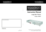
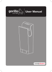
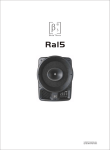
DAILY USE & MAINTENANCE
1
COMPONENTS
External Maintenance
Clean with a soft cloth. If the unit is
very dirty use a soft, dampened cloth
with a neutral cleaning agent,
then polish with a soft, dry cloth
Shell
Power switch
Heat switch
Power light
Water
tray
Sensing
device
•Only use neutral cleaning agents
•Do not use thinners, acidic or alkaline
toilet cleaners or nylon brushes
(they may damage the surface)
•If using chemical cloths, read instructions first
•Disinfecting agents will damage the unit
Operation
light
Outlet
Release clip
Motor
cover
Filtering disk
Cover
Motor
base
Filtering
Tray
2
•If the accumulated water is left in the
drain tank it may degrade and start to smell!
Sensing
device
Excess water tray
Power cable
Release Water
clip
tray
•Regularly wash and disinfect the inside
of the drain tank
3
Outlet
Empty excess water
o prevent water from overflowing
T
it is necessary to regularly empty
the excess water tray
ELECTRICAL SCHEMATIC
To clean the filter
Fuse
Remove the filter unit
Power switch
L
Power
Indicator
N
This should come
out easily by
holding the raised
piece and pulling
gently downwards
Remove the filter
from the unit
User Manual
Sensing
device
Water tray
Clean the filter by
tapping or using a
vacuum cleaner
DO NOT use
water to clean
the filter
Temperature
probe
Sensing
probe
Control
relay
Temperature
switches
Brushed
motor
Replace the filter
every 3 years
Heater
4
Switch power on
Use as normal
Heat switch
Thermal fuse
Place hands
inside the unit,
palms down
Move backwards
and forwards in
the air flow
Turn hands and
repeat backwards
and forwards
motion
Finally rub hands
together to
remove any final
dampness
PACKING LIST
Crocodillo T2 . . . . . . . . . . . . . . . . . . . . . . . . . . . . . . . . . . . . . . . . 1
30mm self tapping screws . . . . . . . . . . . . . . . . . . . . . . . . . . . . . 5
5mm expansion pipe. . . . . . . . . . . . . . . . . . . . . . . . . . . . . . . . . . 1
User manual. . . . . . . . . . . . . . . . . . . . . . . . . . . . . . . . . . . . . . . . . 1
WARNING:
INJURY MAY OCCUR IF MISUSED
•Do not open the front panel – electric shock risk
Prohibited
SPECIFICATION TABLE
Voltage
INSTALLATION
AC2202400V~
Motor
Brush motor
•Do not allow children or adults to pull or hang on
the machine
Phase
Single-phase
Sensing
distance
9–15cm
•Place the unit away from direct water supplies
Input
1400-1650W
Protection
class
IPX4
Air drying
speed
105m/s
Unit
dimensions
250 x 175 x
488mm
Heating
power
800-950W
Net weight
4.3kg
•A suitably rated fused power supply is required
•Ensure the correct power supply is used, if more
than +/-10% the unit may malfunction
•The power must be turned off during maintenance
Do not allow
unit to get
•The drain tank and air filter must be installed for
excessively wet
correct operation
•Ensure the unit has a reliable earth connection
•This hand dryer must be installed by a qualified
electrician
•If the power cord is damaged it must be replaced
by the manufacturer, its service agent or a qualified
person
Follow
instructions
carefully
•A residual current device (RCD) with a rated
residual operating current, not exceeding 30mA
is recommended
•If power tolerance is above +/- 10% the machine
will malfunction
•Please use dedicated spur
•Fix the metal wall plate to the
wall with 5 screws and raw plugs
•A long power cord is supplied
with this machine, trim excess
and connect to junction box
or spur.
Live = brown wire, neutral line = blue
Metal
installation
board
Power
cable
Fixing point
Floor
PRE-INSTALLATION PRECAUTIONS
& INSTALLATION LOCATION
2
DO NOT install in the following places
•Where the temperature can be below -10°C or above 40°C
•Where the unit may come into direct contact with excessive water
Remove water tray
•Using one hand hold the clip open
whilst pulling the tray out with other hand
•If the unit will be in direct or strong sunlight
•If there is a lot of condensation in the environment
•If there are corrosive, neutral or reductive gases present
•20m or more below, or 2000m or higher than, sea level
3
Installation position
The following picture shows the recommended position
•Ensure there is at least 150mm clear space below the machine
(either to the floor or other objects in the location)
•Switch off the power during maintenance
•It is recommended that a minimum distance of100mm should
be left clear to either side of the unit
•Excess water tray and filter must be installed
•Avoid locations where people or doors might damage the unit
•In case of malfunction, switch off power
immediately
Install metal wall plate
Power
supply
cable
•Do not install connected to a power supply
Do not
dismantle
1
•Choose a completely flat wall surface to mount the unit to
Raw plugs
102.5mm
•Ensure power is not connected during installation
Junction box hole
Hang the unit
•Hang the unit on the metal wall plate
•Attach the unit to the wall including
5th fixing screw behind water tray
4
Fix metal wall plate screw
• Remove the filter
•Using the single screw, at an angle
of 45°, fix the unit through the
filter hole, tighten gently until
the unit is fixed firmly to the wall plate
Environmental Protection
•Do not dispose of electrical waste with household
waste, please recycle in appropriate facilities.
Check with your Local Authority or retailer for
recycling advice.
5
Floor
Replace all components
•Replace filter and excess water tray –
See diagram