1
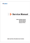
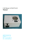
User Manual
Do not attempt to install the unit yourself, unless you are a trained service
technician, or this may affect the safety and functioning of the machine
Read this manual thoroughly before using the unit and retain for future reference
CONTENTS
Contents & Specifications. . . . . . . . . . . . . . . . . . . . . . . . . . . . . . . . . . . . . . . . . . . . . . . . . . . . . . . . . . . . . . . . . . . . . . . 1
Precautions. . . . . . . . . . . . . . . . . . . . . . . . . . . . . . . . . . . . . . . . . . . . . . . . . . . . . . . . . . . . . . . . . . . . . . . . . . . . . . . . . . 2
Component Names & Unit Dimensions. . . . . . . . . . . . . . . . . . . . . . . . . . . . . . . . . . . . . . . . . . . . . . . . . . . . . . . . . . . . . 3
Use . . . . . . . . . . . . . . . . . . . . . . . . . . . . . . . . . . . . . . . . . . . . . . . . . . . . . . . . . . . . . . . . . . . . . . . . . . . . . . . . . . . . . . . . 4
Cleaning . . . . . . . . . . . . . . . . . . . . . . . . . . . . . . . . . . . . . . . . . . . . . . . . . . . . . . . . . . . . . . . . . . . . . . . . . . . . . . . . . . . . 5
Trouble Shooting • Electrical Schematic. . . . . . . . . . . . . . . . . . . . . . . . . . . . . . . . . . . . . . . . . . . . . . . . . . . . . . . . . . . . 6
Pre-installation Precautions. . . . . . . . . . . . . . . . . . . . . . . . . . . . . . . . . . . . . . . . . . . . . . . . . . . . . . . . . . . . . . . . . . . . . . 7
Installation. . . . . . . . . . . . . . . . . . . . . . . . . . . . . . . . . . . . . . . . . . . . . . . . . . . . . . . . . . . . . . . . . . . . . . . . . . . . . . . . . . . 8
Test Run. . . . . . . . . . . . . . . . . . . . . . . . . . . . . . . . . . . . . . . . . . . . . . . . . . . . . . . . . . . . . . . . . . . . . . . . . . . . . . . . . . . . . 9
Packing List. . . . . . . . . . . . . . . . . . . . . . . . . . . . . . . . . . . . . . . . . . . . . . . . . . . . . . . . . . . . . . . . . . . . . . . . . . . . . . . . . 10
SELF PROTECTION
This machine has inbuilt self-protection, which means it will automatically stop working after 25 seconds.
To continue drying withdraw hands and re-insert them
SPECIFICATIONS
2
Rated voltage
AC220 – 240V–
Motor
Brushless DC motor
Input power
1650 – 2050W
Induction method
IR blocking
Wind velocity
95m/S
Protection class
IPX4
Heating power
1000 – 1200W
Dimensions
300 x 215 x 700mm
Net weight
9.5kg
WARNING: Injury may occur if misused
• DO NOT OPEN THE FRONT PANEL – ELECTRIC SHOCK RISK
Prohibited
• DO NOT ALLOW CHILDREN OR ADULTS TO PULL OR HANG ON THE MACHINE
•Place the unit away from direct water supplies
Do not allow unit
to get excessively wet
• A suitably rated fused power supply is required
•Ensure the correct power supply is used, if more than +/-10% the unit may malfunction
Follow instructions
carefully
• The power must be turned off during maintenance
• The drain tank and air filter must be installed for correct operation
• Ensure the unit has a reliable earth connection
Ensure unit
is earthed
• Do not install connected to a power supply
• This hand dryer must be installed by a qualified electrician
•If the power cord is damaged it must be replaced by the manufacturer, its service agent
or a qualified person
•A residual current device (RCD) with a rated residual operating current,
not exceeding 30mA is recommended
Do not
dismantle
• ENVIRONMENTAL PROTECTION
Do not dispose of electrical waste with household waste, please recycle in appropriate
facilities. Check with your Local Authority or retailer for recycling advice.
3
COMPONENTS AND DIMENSIONS
Heater button
Power supply
Power
indicator
Drying time
and fault display
Filter sterilisation
indicator
Fan speed button
Self-check
indicator
Manual power switch
Sensor
Hand drying area
Unit
Lock
Drain hose
Switch door plate
Air inlet panel
Drain outlet
Bottom
Full level
indicator
Drainage tank
Lock
Air inlet
Air filter
85
25
Hook
215
90
300
278
4
638
700
545
Terminal box location
170
USAGE
Stretch out both hands and insert them into the unit
The drying function will start automatically
Pull them back slowly, allowing the water
to blow away
Repeat if necessary
Pull hands out completely
WALL STICKER
Place wall sticker in a prominent position
(the front of the unit or a wall nearby)
10 seconds
www.handydryers.co.uk
5
ROUTINE CLEANING
CLEANING YOUR GORILLO ULTRA
WARNING
Before it gets obviously dirty
•Before cleaning the unit ensure power is
switched off
•DO NOT splash excessive water into the unit
•Clean with a soft cloth.If the unit is very dirty use
a soft, dampened cloth with neutral cleaning agent,
then polish with a soft, dry cloth
• Remove dirt from the sensor (to prevent malfunction)
NOTE
• Only use neutral cleaning agents
•Do not use thinners, acidic or alkaline toilet cleaners
or nylon brushes (they may damage the surface)
Use *alcohol to clean the hand-drying area,
but DO NOT use alcohol anywhere else on the unit
• If using chemical cloths please read instructions first
• Disinfecting agents will damage the unit
*Disinfectant alcohol below 83% concentration
CAUTION
• Wear gloves when cleaning
•The antibacterial coating is effective when bacteria is exposed
to the surface
•The antibacterial coating will become ineffective if the surface
is very dirty
DRAIN TANK MAINTENANCE
CLEANING THE AIR FILTER
Before it fills up (at least once a week)
About once a week
•To prevent water from overflowing it is
necessary to regularly empty the drain tank
•If the accumulated water is left in the drain tank
it may degrade and start to smell!
1
•Open the air inlet panel
Pull the air filter out by
the handle
Gently pull the drain tank out
in a horizontal direction
Full level
2
1
Remove the air filter
Drain tank
1Open the cover and empty
2Wash and disinfect the inside of the drain tank
2
1Cleaning the air filter
Air filter
•Beat it lightly by hand
or use a vacuum cleaner
•You can also use a soft
brush to brush off the dust
3Replace the cover and return to the unit
2Re-attach insert the
correct way around into
the unit and secure the
door shut and lock
Cover
Drain tank
3
NOTE
DO NOT use water to clean the air filter
Add 200cc (about 1 cup)
of clean water through
the drain hole and clean
with supplied brush
(to prevent clogging
with debris)
Drain hole
6
TROUBLE SHOOTING • ELECTRICAL SCHEMATIC
TROUBLE SHOOTING
Problem
Check
Action
No air blows even
if hands are inserted
Are the display indicators lit?
Turn the ground-fault circuit breaker on
Is the power switched on?
Turn the power switch on
Are you putting your hands all the way into
the unit?
Put hands all the way into the unit
Machine continues working
when hands are removed,
screen shows ‘E2’
Is there any dirt or foreign body on the sensor?
Swith off the power button and once the power light has gone off
remove the dirt or foreign body from the sensor. Once finished,
switch the power back on.
No hot air
There is an inbuilt heat sensor in the unit – is
there any dirt on the heating sensor?
Is the ambient temperature higher than 20°C?
Airflow is too low
Has the fuse inside the terminal box blown?
Switch off the power, remove the front cover. There is a terminal
box inside, take the cover off this. Check whether the fuse inside
the terminal box has blown.
Is the speed button set to low level?
Turn the speed button to the high setting
If the above actions do not work, turn off the power and call your dealer to inspect and repair your unit, if necessary.
ELECTRICAL SCHEMATIC
Motor
Control PCB
Fuse
Temperature Thermal protection
probe
switch
Thermal
circuit breakers
Power
switch
Heaters
Wiring
terminal
blocks
Fuse
Compensation
probe
Sensors
receiving PCB
Temperature
probe
Display
PCB
Sensors
start PCB
Power
Power
indicator light
State indicator
light
Status
Introductions
Status
Lit
Power on
Off
Off
Machine not in use
Flashing light
Introductions
Solution
Power not supplied
Check external power source, close
the power switch
Master board fuse
blown
Repair fuse
Motor fault, it won’t
operate nomally
Check motor connecting wires and
the clear any foreign objects
Used for longer
than 25s
Clear workspace of foreign objects,
restart to work
Digital Readout
Timing digital
tube
E1
Motor fault, nomally
E2
Run time longer
than 25s
Clear workspace of foreign objects,
restart to work
E3
Incorrect voltage/power
surge
E4
Voltage drop
Check the power supply circuit
E5
Machine temperature
higher than 80°C
E6
Master board temperature is higher than 80°C
Ensure the air inlet and outlet are
clear of foreign objects
E8
Fan fault
Check the fan sensor connection
7
PRE-INSTALLATION PRECAUTIONS
There are locations unsuitable for this unit.
DO NOT install in the following types of location:
•Where the temperature can be below -10°C or above 40°C
•Where the unit may come into direct contact with water
•If the unit will be in direct or strong sunlight
•If there is a lot of condensation in the environment
•If there are corrosive, neutral or reductive gases present
•20m or more below, or 2000m or higher than, sea level
Installation location considerations:
•Install the unit in a position where the unit will be easy to use.
Note that if the unit is installed too low it may get wet when the floor is cleaned
•Ensure there is at least 150mm clear space below the machine
(either to the floor or other objects in the location)
•It is recommended that a minimum distance of100mm should
be left clear to either side of the unit
•Avoid locations where people or doors might damage the unit
•Choose a completely flat wall surface to mount the unit to
Spur location:
•Connect directly to fused spur, ensuring spur is at least 300mm away from the machine
(never directly above or below the unit)
Fixed screws
Installation panel
Unit
Safety screws
Recommended
installation heights
890mm (for gents)
870mm (for ladies)
Drain tank
Power switch
Installation panel
Air filter
8
Terminal box
630mm
Distance between the
terminal box without
cover and ground
INSTALLATION
Use a single-phase alternating rated voltage supply
(Not to be used with a power supply exceeding ±10%)
Use a power cord between 2mm2 and 2.5mm2 thick
(A voltage drop is possible if longer than 11m, so we recommend using 2.5mm2 cable)
Power cord
(with earth)
Embed a backbox in the installation location (1 switchbox no cover)
•If no backbox is used the power cord may prevent
the unit from sitting flush against the wall
3
•If the wall is concrete, use metal screw plugs
(raw plugs etc)
•If the wall is not concrete, reinforce it prior
to installation
•Place the drilling template onto the wall
and drill holes
•Place rawplugs into the holes and screw
on mounting plate as shown
1Remove the drain tank and air filter
Drilling
template
Installation
screws
Installation
panel
Switchbox
Security
screw holes
870–890mm
Attach the installation panel to the wall using the 5 screws supplied
870–890mm
2
m
0m
40
615mm
1
Wire the unit
130mm
2 Remove electric cover and power cords
iUnscrew the 2 screws on theTerminal
electricbox
cover
Drain tank
and remove lid
line
iiUnscrew the 2 screws on the Pressure
pressure
line cover,
Air filter
cover
loosen the 3 screws on terminal box, then pull out
the power line
Drain tank
Air filter
Electric
Terminal
boxcover
Power cords
Pressure line
cover
Electric cover
Power cords
9
INSTALLATION
4
Replace the terminal block cover
Terminal box
•Ensure power cables sit within the cabling channel
and the terminal block cover is flat after installation
Pressure line
cover
Power cords
Electric cover
5
6
Fix the unit
•Tidy the power lines and press any excess into the terminal
block on the wall
•Hang on metal wall brackets and ensure it sits flush to the wall
• Install the safety screws (x 2)
Unit
NOTE: the unit must be installed with the
safety screws or it will be unstable
Safety
screw
Hook
1Replace the air filter
Unit
•Carefully push the air filter up into the unit, close the air inlet
door and lock it with the catch
2Replace the drain tank
•Push the drain tank into the unit, as shown
10
Installation panel
Drain
tank
Air
filter
PACKING LIST
Unit . . . . . . . . . . . . . . . . . . . . . . . . . . . . . . . . . . . . . . . . . . . . . . . . . . . . . . . . . . . . . . . . . . . . . . . . . . . . . . . 1
Mounting plate . . . . . . . . . . . . . . . . . . . . . . . . . . . . . . . . . . . . . . . . . . . . . . . . . . . . . . . . . . . . . . . . . . . . . . 1
5mm Expansion pipe. . . . . . . . . . . . . . . . . . . . . . . . . . . . . . . . . . . . . . . . . . . . . . . . . . . . . . . . . . . . . . . . . . 6
5 x 30 Self-tapping screws. . . . . . . . . . . . . . . . . . . . . . . . . . . . . . . . . . . . . . . . . . . . . . . . . . . . . . . . . . . . . 6
User manual (including Packing List and Warranty Card). . . . . . . . . . . . . . . . . . . . . . . . . . . . . . . . . . . . . . 1
Method of use figure. . . . . . . . . . . . . . . . . . . . . . . . . . . . . . . . . . . . . . . . . . . . . . . . . . . . . . . . . . . . . . . . . . 1
Drilling template . . . . . . . . . . . . . . . . . . . . . . . . . . . . . . . . . . . . . . . . . . . . . . . . . . . . . . . . . . . . . . . . . . . . . 1
11
www.handydryers.co.uk