1
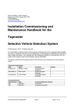
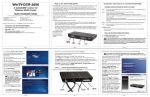
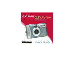
CMOR
Professional IR Dome
User Manual
Product ranges covered by this manual
CMOR D4
Vi-AL1A
Vi-PSU-1
Options
Document Reference
Date
Firmware
Vc607a.doc
14/12/2012
From Vc006-210
Videoswitch
Telephone
01252-851510
Ocean House, Redfields Industrial Park
Fax
01252-851296
Redfields Lane, Church Crookham
Email
[email protected]
Hants GU52 0RD
Web
www.videoswitch.co.uk
Videoswitch
Page 1
Vc607a.doc
Contents
1
Installing the Dome ..................................................1
1.1
Vi-B2 Wall Bracket .................................................................................................................1
1.1.1
Fixing the mounting plate...................................................................................................1
1.1.2
Securing the bracket ..........................................................................................................1
1.1.3
Attaching the CMOR Dome ...............................................................................................2
1.1.4
Attaching the umbilical cable .............................................................................................2
1.1.5
Fitting the bracket cover.....................................................................................................3
1.2
Vi-B4 Pendant Bracket...........................................................................................................3
1.3
Vi-B4 Swan-Neck Bracket......................................................................................................3
1.4
Vi-B5 Corner Adaptor.............................................................................................................4
1.5
Vi-B6 Pole Adaptor ................................................................................................................4
2
Installing Power Supply ...........................................5
2.1
Fixing power supply to a wall .................................................................................................5
2.2
Power Supply Connections ....................................................................................................5
2.2.1
Mains Input ........................................................................................................................6
2.2.2
Connections to dome .........................................................................................................6
2.2.3
Connections to DVR ..........................................................................................................6
3
Configuring the Dome..............................................7
3.1
CMOR D4 Configuration ........................................................................................................7
3.1.1
Auto-Protocol and Auto-Baud ............................................................................................7
3.1.2
Address ..............................................................................................................................7
3.1.3
Clear Address ....................................................................................................................8
3.1.4
Reset Address ...................................................................................................................8
3.1.5
Termination ........................................................................................................................8
4
Menus ........................................................................9
4.1
Menu Navigation ....................................................................................................................9
4.1.1
Entering Menu....................................................................................................................9
4.1.2
Moving cursor ....................................................................................................................9
4.1.3
Select .................................................................................................................................9
4.1.4
Cancel ................................................................................................................................9
4.1.5
Exit Menu .........................................................................................................................10
4.2
Menu Summary....................................................................................................................10
4.3
Login ....................................................................................................................................12
4.3.1
Display .............................................................................................................................13
4.3.2
Information Screens.........................................................................................................13
4.3.3
Date/Time ........................................................................................................................13
4.3.4
Camera Title ....................................................................................................................13
4.3.4.1
4.3.5
4.4
Coordinate Display .........................................................................................13
Show Preset During Tours...............................................................................................13
Setup....................................................................................................................................13
4.4.1
Dome Address .................................................................................................................13
4.4.2
Passwords .......................................................................................................................13
4.4.3
Datum Checks .................................................................................................................13
4.4.4
Install date........................................................................................................................14
4.4.5
4.4.6
Clear Settings ..................................................................................................................14
4.4.5.1
Clear all presets .............................................................................................14
4.4.5.2
Clear all tours .................................................................................................14
4.4.5.3
Clear privacy masks .......................................................................................14
4.4.5.4
Clear configuration .........................................................................................14
4.4.5.5
Clear everything .............................................................................................14
4.4.5.6
Reboot ............................................................................................................14
Coax Validate Bytes.........................................................................................................14
Videoswitch
Page 2
Vc607a.doc
4.4.7
4.5
Language .........................................................................................................................14
Lamps ..................................................................................................................................15
4.5.1
Mode ................................................................................................................................15
4.5.2
ON level ...........................................................................................................................15
4.5.3
Off level hysteretic ...........................................................................................................15
4.5.4
Auto lamp delay ...............................................................................................................15
4.5.5
Lam schedule...................................................................................................................15
4.5.6
4.6
4.6.1
Lamp Power .....................................................................................................................15
Camera ................................................................................................................................16
Camera settings ...............................................................................................................16
4.6.1.1
Shutter Speed
16
4.6.1.1.2
Exposure Compensation
16
4.6.1.1.3
Joystick Focus Mode
16
4.6.1.1.4
Preset Focus Mode
16
4.6.1.1.5
Zoom Limit
16
4.6.1.1.6
Backlight compensation
16
4.6.1.1.7
Noise Reduction
16
4.6.1.1.8
Wide Dynamic Range
16
4.6.1.1.9
High Resolution Mode
16
4.6.1.1.10
Image Stabiliser
16
4.6.1.2
4.6.2
Day Settings (Lamps OFF).............................................................................16
4.6.1.1.1
Night Settings (Lamps ON) ............................................................................16
4.6.1.2.1
Shutter Speed
16
4.6.1.2.2
Exposure Compensation
16
4.6.1.2.3
Joystick Focus Mode
16
4.6.1.2.4
Preset Focus Mode
16
4.6.1.2.5
Zoom Limit
16
4.6.1.2.6
Backlight compensation
16
4.6.1.2.7
Noise Reduction
17
4.6.1.2.8
Wide Dynamic Range
17
4.6.1.2.9
High Resolution Mode
17
4.6.1.2.10
Image Stabiliser
17
Context Camera Settings.................................................................................................17
4.6.2.1
Not available...................................................................................................17
4.6.3
Low ligh mode at night .....................................................................................................17
4.6.4
IR focus correction ...........................................................................................................17
4.6.5
Enable digital zoom..........................................................................................................17
4.6.6
Video Gain .......................................................................................................................17
4.6.7
4.7
Video Lift ..........................................................................................................................17
Keyboard..............................................................................................................................17
4.7.1
Restore Mode (Preset & Tours) .......................................................................................17
4.7.2
Restore delay (Preset & Tours) .......................................................................................17
4.7.3
Joystick/Speed Curve ......................................................................................................17
4.7.4
Zoom Ratio ......................................................................................................................17
4.7.5
Max Joystick Speed .........................................................................................................18
4.7.6
4.7.7
4.8
4.8.1
Pan Limits ........................................................................................................................18
4.7.6.1
Use Pan Limits ...............................................................................................18
4.7.6.2
Set right limit...................................................................................................18
4.7.6.3
Set left Limit....................................................................................................18
Iris key usage...................................................................................................................18
Presets .................................................................................................................................18
Edit Presets......................................................................................................................18
4.8.1.1
Set Preset.......................................................................................................18
4.8.1.2
Auto Set Preset ..............................................................................................18
4.8.1.3
Clear Preset ...................................................................................................18
4.8.1.4
Title.................................................................................................................18
4.8.1.5
Preset Dwell Time ..........................................................................................18
Videoswitch
Page 3
Vc607a.doc
4.8.1.6
4.9
Preset Speed..................................................................................................18
Tours ....................................................................................................................................19
4.9.1.1
Edit Tour .........................................................................................................19
4.9.1.1.1
Edit tour
19
4.9.1.1.2
Add all preset to tour
19
4.9.1.1.3
Clear Tour
19
4.9.1.1.4
Title
19
4.9.1.1.5
Echedule
19
4.10
Privacy .................................................................................................................................19
4.11
Alarms ..................................................................................................................................20
4.11.1
Enable Alarms..................................................................................................................20
4.11.2
Alarm override time..........................................................................................................20
4.11.3
New alarm dwell...............................................................................................................20
4.11.4
Alarm cycle time...............................................................................................................20
5
Technical Data ........................................................21
5.1
Vi-D4 Domes........................................................................................................................21
5.1.1
Camera ............................................................................................................................21
5.1.2
IR Illumination ..................................................................................................................21
5.1.3
Power requirements.........................................................................................................21
5.1.4
5.2
Physical and Environmental.............................................................................................21
Vi-PSU-1A Power Supply ....................................................................................................21
5.2.1
Power ...............................................................................................................................21
5.2.2
Alarm Module Selection ...................................................................................................21
5.2.3
Physical and Environmental.............................................................................................21
5.2.4
5.3
5.3.1
5.3.2
5.4
Safety...............................................................................................................................21
Vi-ALM1A Alarm Module......................................................................................................22
Alarm Inputs/Outputs .......................................................................................................22
Physical and Environmental.............................................................................................22
Brackets and Cables ............................................................................................................22
5.4.1
Vi-B2 Wall bracket ...........................................................................................................22
5.4.2
Vi-B5 Corner adaptor .......................................................................................................22
5.4.3
Vi-B4 Swan-neck bracket.................................................................................................22
5.4.4
Vi-B3 Pendant bracket .....................................................................................................22
5.4.5
Vi-B6 Pole mount bracket ................................................................................................22
5.4.6
Vi-B7 Dome adaptor ........................................................................................................22
5.4.7
Vi-B8 Ceiling Mount Kit ....................................................................................................22
5.4.8
5.5
Cables ..............................................................................................................................22
CE Marking ..........................................................................................................................22
Videoswitch
Page 4
Vc607a.doc
CMOR Dome
1 Installing the Dome
1.1 Vi-B2 Wall Bracket
The wall bracket allows the dome to be mounted to a vertical wall. The wall bracket may
also be used in conjunction with the Vi-B5 corner adaptor and the Vi-B6 pole adaptor for
mounting the dome on the corner of a building or on a pole.
1.1.1 Fixing the mounting plate
•
Fix the mounting plate to the wall (or corner or pole adaptor), using four screws (A)
of adequate size and strength to support the weight of the dome.
•
Fit the umbilical cable, entering either through the mounting plate or via a knockout
in the bottom of the plastic bracket covers.
1.1.2 Securing the bracket
•
Secure the bracket to the mounting plate using the 4 nuts supplied (C)
•
For safety reasons, at least one of the fixing screws must have washer fitted (D).
•
Position the umbilical cable (E) such that the connector (F) is above the dome
support cradle (G)
Videoswitch
Page 1
Vc607a.doc
CMOR Dome
1.1.3 Attaching the CMOR Dome
•
Fully loosen the locking ring (C) by rotating clockwise until it nearly touches the top
of the dome
•
Lift the dome (taking care not to lift it using lamps) and place the dome support plate
(A) onto the dome support cradle (B). Note that the curved side of the support plate
goes to the back.
•
Rotate the locking ring (C) counter-clockwise to lock the dome firmly in position.
1.1.4 Attaching the umbilical cable
•
Plug the waterproof connector on the umbilical cable into the top of the dome
•
Turn the locking ring (A) clockwise to secure the connector
Videoswitch
Page 2
Vc607a.doc
CMOR Dome
1.1.5 Fitting the bracket cover
•
Locate the two plastic sides of the cover on the metal support bracket
•
Fix together with the supplied screw using the supplied Allen key
1.2 Vi-B4 Pendant Bracket
The pendant bracket allows the dome to be mounted under a horizontal surface such as a
ceiling.
•
Secure the mounting end of the pendant bracket to the ceiling.
•
Make sure the protective cup is in place on the pole
•
Securely attach the mounting bracket using the screws provided.
•
Then attach the dome and umbilical cable in the same was as described in previous
paragraphs 1.1.3 and 1.1.4.
•
Slide down the protective cup.
1.3 Vi-B4 Swan-Neck Bracket
The swan-neck bracket allows the dome to be mounted above a horizontal surface such as
a roof, pillar top or other horizontal surface.
•
Secure the mounting end of the swan-neck bracket to the surface.
•
Make sure the protective cup is in place on the pole.
•
Securely attach the mounting bracket using the screws provided.
•
Attach the dome and umbilical cable in the same was as described in previous
paragraphs 1.1.3 and 1.1.4.
•
Slide down the protective cup.
Videoswitch
Page 3
Vc607a.doc
CMOR Dome
1.4 Vi-B5 Corner Adaptor
Use this in conjunction with the Vi-B2 wall bracket to mount the dome on the corner of a
building.
1.5 Vi-B6 Pole Adaptor
Use this in conjunction with the Vi-B2 wall bracket to mount the dome onto a pole.
Videoswitch
Page 4
Vc607a.doc
CMOR Dome
2 Installing Power Supply
The CMOR dome runs from 24V DC. The Videoswitch Vi-PSU1 Power Supply must be
used to power the CMOR dome. The Vi-PSU1 is housed in a weatherproof box that may be
mounted externally or internally. Never apply 24AC to the standard DC dome.
2.1 Fixing power supply to a wall
•
Fit the optional alarm module (A) into the power supply using the 4 screws provided.
•
For safety reasons never remove the slotted metal cover (B).
•
Fix the power supply to a wall using a screw in each of the four corner holes (C).
2.2 Power Supply Connections
Videoswitch
Page 5
Vc607a.doc
CMOR Dome
2.2.1 Mains Input
Connect the incoming fused mains power to the terminal block marked MAINS INPUT
making sure the LIVE, NEUTRAL and EARTH wires are correctly connected.
Identification
MAINS INPUT
Live
Live (brown) 240Vac 50Hz
Neutral
Neutral (blue) 240Vac 50Hz
Earth
Earth (Yellow/Green)
2.2.2 Connections to dome
Connect the umbilical cable from the dome to the terminal block marked DOME.
Identification
DOME
CAM2
White Coax signal (dual camera version only)
GND
White Coax screen (dual camera version only)
CAM1
Black Coax signal
GND
Black Coax screen
RS485 (A)
WHITE
RS485 (B)
ORANGE
+24V
RED
0V
BLACK and Cable screen
2.2.3 Connections to DVR
Connections to the DVR or other recording/control equipment should be made to the
terminal block marked DVR/KBD/MONITOR.
Identification
DVR/KBD/MONITOR
CAM2*
Camera input (dual camera version only)
GND
CAM1*
Camera input
GND
RS485 (A)
RS485 (A) or (+) dome output
RS485 (B)
RS485 (B) or (-) dome output
Spare
Not connection
GND
RS485 ground
1
*Note that the video connection(s) made be made either using the BNC connectors or
the screw terminals, whichever is more convenient.
Videoswitch
Page 6
Vc607a.doc
CMOR Dome
3 Configuring the Dome
3.1 CMOR D4 Configuration
3.1.1 Auto-Protocol and Auto-Baud
The CMOR D4 will automatically detect the protocol and the baud rate. There is no need to
set anything, just start sending commands to the dome and it will detect the protocol and
baud rate.
Currently supported protocols are:
•
Videoswitch VXP-4 (RS485)
•
Pelco-D (RS485)
•
Pelco-P (RS485)
•
Vista (RS485)
•
BBV up-the-coax
Supported baud rates are:
•
2400
•
4800
•
9600
Note: There are no DIP switches fitted on the D4 dome, so do not remove the large plug in
rear of the hemisphere.
If the dome keeps searching for the protocol due to spurious signals on the RS485 line, the
protocol may be locked in the menu once communication is established. Do not lock
protocol if an alarm module is being used.
3.1.2 Address
If you are using the dome via BBV up-the-coax control, there is no need to set the address
and this section can be ignored.
In the case of RS485 control, the CMOR D4 will initially respond to all addresses. If several
domes are connected they will all respond to commands until individual addresses have
been stored in each dome.
To store an address via the menu:
1. Select the dome you wish to configure on the DVR or other controller
2. Enter the dome Menu (e.g. SET Preset 95 for Pelco)
3. Move cursor Down, then Right to enter the Address menu
4. Move cursor Right to enter Set Address option
5. Use Up/Down and Left/Right to copy the displayed 6 digit number.
6. Use Left to exit
The dome address will now be set to match the address (camera number) that you are
currently talking to the dome with.
As the 6 digit number is unique, only the address of the current dome is set. Repeat for all
other CMOR domes in the system.
Videoswitch
Page 7
Vc607a.doc
CMOR Dome
3.1.3 Clear Address
If the address of a dome has been set but needs changing, you either need to
•
Communicate with it using its currently set camera address or
•
Use up-the-coax control.
Enter the Address menu, then the the Clear Address option to delete the address. The
dome will then respond to all addresses again.
3.1.4 Reset Address
If you wish to clear the addresses of all connected domes, do the following:
Issue five SET Preset 90 commands in succession, not more than 5 seconds apart. This
will reset the dome address of all connected domes.
3.1.5 Termination
Termination of the RS485 in the dome is normally set ON.
If you do need to turn the termination of a dome OFF, enter the dome Setup menu and turn
the termination off.
•
If you are using a star expander (eg. Videoswitch Vi-E2) to drive multiple domes all
domes should be have termination ON. This is the recommended method of
connecting to multiple domes.
•
If you are using an alarm module, termination in the dome should also always be
ON.
•
If you are daisy-chaining domes without alarm modules, for all except the last in the
daisy chain, you will need to turn the termination OFF. The dome at the end of the
daisy chain must have its termination ON.
•
If you are daisy-chaining domes with Vi-AL1A alarm modules, make sure the
termination of all domes is ON. The Vi-AL1A alarm module always terminates the
RS485.However, it provides an active output which regenerates the RS485 signal,
so use this to connect to the next dome in the chain.
Videoswitch
Page 8
Vc607a.doc
CMOR Dome
4 Menus
4.1 Menu Navigation
4.1.1 Entering Menu
Different keyboards have different ways of entering the menu system of a dome. Refer to
specific keyboard manual for details.
Common examples are:
•
Videoswitch Vi-K2
Press DOME then press MENU
•
Videoswitch Vi-K3
Press and hold ALT then press DOME MENU
•
BBV (TX400)
Press and hold SHIFT then press 1
•
Pelco (KBD400A)
Enter 95 then press and hold PRESET key
•
Dedicated Micro DS2
Press and hold * 8,8,910,10,2
4.1.2 Moving cursor
Once in the menu, the joystick may be used for LEFT, RIGHT, UP and DOWN control of the
cursor. On a Videoswitch keyboard, the cursor keys can also be used.
•
UP
move the cursor up, or change a value
•
DOWN
move the cursor down, or change a value
•
RIGHT
move the cursor right, or enter a sub-menu
•
LEFT
move the cursor left, or exit a sub-menu. When editing a
title, you may need to go LEFT several times to exit
4.1.3 Select
Use of Select is not necessary – if there is no joystick movement and no key is pressed for 5
seconds (programmable), the dome will automatically issue a select command, for example
to save a preset or mask.
If you wish to issue a Select command to avoid having to wait, the required key depends on
the type of keyboard.
Common examples are:
•
Videoswitch Vi-K2
-
Press OK
•
Videoswitch Vi-K3
-
Press OK
•
BBV (TX400)
-
Press 1
•
Pelco (KBD400A)
-
Enter 96 then press and hold PRESET key
•
DS2
Press Preset,10, then preset number e.g.1,2
4.1.4 Cancel
Use of Cancel is not essential, but can be used to quit a preset without setting it. This also
depends on the type of keyboard.
Common examples are:
•
Videoswitch Vi-K2
-
Press BACK or WASH
•
Videoswitch Vi-K3
-
Press ALT and ESC
•
BBV TX400
-
Press WASH
•
Pelco
-
Enter 97 then press and hold PRESET key
Videoswitch
Page 9
Vc607a.doc
CMOR Dome
4.1.5 Exit Menu
Leave the menu by going LEFT out of all levels until you leave the menu. The menu will also
exit automatically if not used for 5 minutes.
All changes made will be saved when the menu is left. The message “Saved OK” will flash
up on the screen to confirm this
The menu structure is summarised below and the following section gives more details on
individual menu items. Note that the menu structure may differ slightly depending on the
version of firmware installed in the dome and on the camera(s0 that are installed in the
dome.
4.2 Menu Summary
Login
Display
Information screens
System
Status
Alarms
Camera
Coax
Date/Time
Enter date/time
Daylight saving
Display
Position on screen
Row
Column
Title
Title
Display
Position on screen
Row
Column
Coordinate display
Display
Coordinates position
Row
Column
Show presets during tours
Startup screen timeout
Setup
Dome Address
Set address
Clear address
RS485 Termination
Passwords
Installer password
Supervisor password
User password
Datum checks
Periodic datum check
Datum check time
Mis-alignment threshold
Install date
Clear settings
Clear all presets
Clear all tours
Clear all privacy masks
Clear configuration
Clear everything
Reboot
Coax validate bytes
Language
Lamps
Mode
ON level
OFF level hysteresis
Auto lamp delay
Lamp schedule
Lamp Power
Videoswitch
Page 10
Vc607a.doc
CMOR Dome
Camera
Camera settings
Day settings (lamps off)
Shutter speed
Exposure compensation
Joystick focus mode
Preset focus mode
Zoom Limit
Backlight compensation
Noise reduction
Wide dynamic range
High resolution mode
Image stabiliser
Night settings (lamps on)
Shutter speed
Exposure compensation
Joystick focus mode
Preset focus mode
Zoom Limit
Backlight compensation
Noise reduction
Wide dynamic range
High resolution mode
Image stabiliser
Context camera settings
Day settings (lamps off)
Shutter speed
Exposure compensation
Joystick focus mode
Preset focus mode
Backlight compensation
Noise reduction
Wide dynamic range
High resolution mode
Image stabiliser
Night settings (lamps on)
Shutter speed
Exposure compensation
Joystick focus mode
Preset focus mode
Backlight compensation
Noise reduction
Wide dynamic range
High resolution mode
Image stabiliser
Low light mode at night
IR focus correction
Enable digital zoom
Invert camera image
Mirror camera image
Video Gain
Video Lift
Keyboard
Restore mode
Restore delay
Auto-select time-out
Joystick/Speed Curve
Zoom ratio
Max joystick speed
Pan limits
Use pan limits
Set right limit
Set left limit
Iris key usage
Zoom Lock
Presets
Edit presets
Preset 1 to 255
Set preset
Auto-set presets
Clear preset
Title
Preset dwell time
Preset speed
Default dwell
Default speed
Videoswitch
Page 11
Vc607a.doc
CMOR Dome
Freeze between presets
Tours
Edit tour
Tour 1 to 16
Edit tour
Add all presets to tour
Clear tour
Title
Schedule
Privacy
Mask 1 to 30
Set privacy mask
Clear privacy mask
Zoom Threshold
Alarms
Enable alarms
Alarm override time
New alarm dwell
Alarm cycle time
4.3 Login
The dome comes with no installer password set, so no login is required initially.
However, is is recommended that passwords are set (via the Setup/Password menu) once
the dome has been configured to protect the configuration from unwanted changes.
There are three levels of password access, gained but three different password: Installer,
Supervisor and User. Different parts of the menu are protected by the different levels. The
Installer password gives access to the whole menu, Supervisor gives access to some items
and User gives access to fewest items
When all three passwords have been set (i.e. to something other than 0000), you will need
to login to access the various sub-menus.
To login, enter the menu system, move RIGHT to enter the Login screen.
Use RIGHT and LEFT to move the cursor and UP and DOWN to change the digits. When
you have entered the correcty password, go LEFT repeatedly to exit the login screen. A
message will appear on the screen to indicate whether you have successfully logged in, and
with which level of access rights.
Default passwords:
User
1111
Supervisor
2222
Installer
0000 (no login required)
Once logged in, you remain logged in for 5 minutes from last use of the menu, even if you
exit and re-enter the menu. If you want to log out more quickly to prevent unauthorised
access, just enter an invalid password.
Videoswitch
Page 12
Vc607a.doc
CMOR Dome
4.3.1
Display
4.3.2 Information Screens
There are a number of information screens that can be displayed for diagnostic purposes.
The System screen is useful to find out the serial number and model of the dome and check
which protocol, baud rate and address is being used
4.3.3 Date/Time
This menu allows you to set the date and time and specify whether automatic daylight
saving mode is used (i.e. change the clocks at the correct times in autumn and spring). You
may also specify whether the time is displayed and where on the screen.
Even if the clock is not being displayed, it is still used for daily datum checks and for
scheduling the lamps and tours if these features are selected.
4.3.4 Camera Title
A title for the dome camera may be entered if required and optionally displayed anywhere
on the screen.
4.3.4.1 Coordinate Display
This option allows the pan and tilt coordinates and the zoom level to be displayed on the
screen.
4.3.5 Show Preset During Tours
This option determines whether or not the preset titles are displayed while a tour is in
progress.
4.4 Setup
4.4.1 Dome Address
When using RS485 control the dome address is set or cleared in this menu. To set the
dome address, enter the displayed 6-digit number and the dome address will be set to the
address that is currently being used to talk to the dome (this is displayed for reference).
4.4.2 Passwords
The default installer password is 0000 which means the dome can be fully setup without
requiring a password, It is recommended that passwords are set to prevent the user from
altering important settings. Take care to make a note of the new passwords.
4.4.3 Datum Checks
The dome can be set to perform a datum check every 24 hours, at a programmable time of
day. This means that the dome will pan and tilt for a few seconds while it performs a self test
and checks its alignment. It will revert to an existing preset or tour when the process is
complete. This ensures that maximum accuracy is maintained. The feature may be turned
off if required.
The dome may also perform a datum check if a misalignment is detected. The threshold
determines how much mis-alignment must occur in order to trigger a datum check.
Videoswitch
Page 13
Vc607a.doc
CMOR Dome
4.4.4 Install date
The date and time of installation may be set here to provide a record for future service or
maintenance purposes.
4.4.5 Clear Settings
4.4.5.1 Clear all presets
To clear all the presets, enter this menu, use UP to select YES and go LEFT to exit.
4.4.5.2 Clear all tours
To clear all the tours, enter this menu, use UP to select YES and go LEFT to exit.
4.4.5.3 Clear privacy masks
To clear all privacy settings, enter this menu, use UP to select YES and go LEFT to exit.
4.4.5.4 Clear configuration
To clear the menu configuration to the factory defaults, enter this menu, use UP to select
YES and go LEFT to exit.
4.4.5.5 Clear everything
To clear the configuration, presets and tours, enter this menu, use UP to select YES and go
LEFT to exit.
4.4.5.6 Reboot
To restart the dome (equivalent to power cycling), enter this menu, use UP to select YES
and go LEFT to exit.
Note that any unsaved changes to the configuration will be lost when this is done.
4.4.6 Coax Validate Bytes
The dome rejects interference that could be otherwise be decoded as telemetry commands
by checking that a steady stream of valid data is being received. This setting determines
how many good bytes of data have to be received before the telemetry is deemed good.
Increase it to eliminate interference or decrease it if the control is unreliable from a noncompliant controller. The normal setting is 4.
4.4.7 Language
The language used in the menus may be set here. Currently English and French are
supported.
Videoswitch
Page 14
Vc607a.doc
CMOR Dome
4.5 Lamps
Options relating to the built-in lamps are set in this sub-menu.
4.5.1 Mode
This option determines when the lamps are turned on:
Light sensing (default) -
the lamps turn on automatically when it gets dark
Timed
-
the lamps turn on according a time of day schedule
Manual
-
the lamps turn on and off under manual control
4.5.2 ON level
Set this number to specify the light level at which the IR lamps turn on. The lower the
number the darker the light has to get before the lamps come on. The default setting is 75.
The current light reading is displayed which can be useful if you want to note the light level
at dusk when you want the IR lamps to come on.
4.5.3 Off level hysteretic
The IR lamps are turned off when the light level rises to the ON level plus this hysteresis
value. The default is 125.
4.5.4 Auto lamp delay
Set the time in seconds that you want the dome to wait before switching on or off due to a
change in light level. This delay stops the dome responding to short term effects like car
headlights that would otherwise cause the IR lamps to switch.
4.5.5 Lam schedule
If the Lamp Mode is timed, use this option to specify the hours during each day that you
want the lamps to be on. A solid block indicates that the lamps will be ON for that hour
period. A dash indicates that they will be OFF. There are a total of 24 positions, one for
each hour of the day. Go LEFT to exit.
4.5.6 Lamp Power
The power of the lamps may be set here. For maximum range set to 100%. For maximum
life or if in confined area, reduce slightly.
Videoswitch
Page 15
Vc607a.doc
CMOR Dome
4.6 Camera
4.6.1 Camera settings
4.6.1.1 Day Settings (Lamps OFF)
These settings apply when the IR lamps are not on.
4.6.1.1.1 Shutter Speed
The shutter speed may be slowed down to achieve greater light sensitivity. Normally this
should be set to AUTO.
4.6.1.1.2 Exposure Compensation
The brightness of the imagfe can be adjusted here
4.6.1.1.3 Joystick Focus Mode
There are two settings; Auto & Manual. The default setting for DAY is AUTO.
4.6.1.1.4 Preset Focus Mode
There are two settings; Auto & Stored. The default setting for DAY is AUTO.
4.6.1.1.5 Zoom Limit
The zoom limit can be adjusted from1 – 100%
4.6.1.1.6 Backlight compensation
Backlight compensation can be turned ON or OFF
4.6.1.1.7
Noise Reduction
4.6.1.1.8
Wide Dynamic Range
4.6.1.1.9
High Resolution Mode
4.6.1.1.10 Image Stabiliser
4.6.1.2 Night Settings (Lamps ON)
These settings apply when the IR lamps are on.
4.6.1.2.1 Shutter Speed
The shutter speed may be slowed down to achieve greater light sensitivity. Normally this
should be set to AUTO.
4.6.1.2.2 Exposure Compensation
The brightness of the imagfe can be adjusted here
4.6.1.2.3 Joystick Focus Mode
There are two settings; Auto & Manual. The default setting for DAY is AUTO.
4.6.1.2.4 Preset Focus Mode
There are two settings; Auto & Stored. The default setting for DAY is AUTO.
4.6.1.2.5 Zoom Limit
The zoom limit can be adjusted from1 – 100%
4.6.1.2.6 Backlight compensation
Backlight compensation can be turned ON or OFF
Videoswitch
Page 16
Vc607a.doc
CMOR Dome
4.6.1.2.7
Noise Reduction
4.6.1.2.8
Wide Dynamic Range
4.6.1.2.9
High Resolution Mode
4.6.1.2.10 Image Stabiliser
4.6.2 Context Camera Settings
4.6.2.1
Not available
4.6.3 Low ligh mode at night
4.6.4 IR focus correction
4.6.5 Enable digital zoom
This option selects whether you want to be able to zoom beyond the optical zoom limit and
use digital zoom. The default setting is OFF.
4.6.6 Video Gain
The video gain may be set from 0 to 7 to compensate for losses in long cable runs. Default
is 0.
4.6.7 Video Lift
The high frequency video lift may be set from 0 to 8 to compensate for losses in long cable
runs. Default is 0.
4.7 Keyboard
This sub menu selects options relating to manual control from the joystick keyboard.
4.7.1 Restore Mode (Preset & Tours)
Set this option if you want the dome to revert to a TOUR or PRESET 1 after a specified
period (in seconds) of inactivity.
If the restore mode is not required select OFF
4.7.2 Restore delay (Preset & Tours)
Select restore delay time in seconds. Select 180 seconds to OFF
4.7.3 Joystick/Speed Curve
This option determines the relationship between the joystick offset and the pan/tilt speed
and the setting is a matter of user preference. If linear, the relationship is proportional. If
quasi-linear or non-linear, the movement is slow to start with and increases rapidly as the
joystick is moved more. The default is quasi-linear.
4.7.4 Zoom Ratio
This setting determines how much the pan and tilt slows down as you zoom in and the
setting is a matter of user preference. This slow down helps fine control of the dome position
when zoomed in on a target. The default setting is 16.
Videoswitch
Page 17
Vc607a.doc
CMOR Dome
4.7.5 Max Joystick Speed
This setting affects pan and tilt and determines how fast the dome moves for a full deflection
of the joystick. Generally control is easier if it is set to less than 100%. The default is 60%.
4.7.6 Pan Limits
4.7.6.1 Use Pan Limits
If you wish to stop the dome from panning all the way round, for example if it is mounted on
a wall or corner, set this option (after you have set the right and left limits). Once set, the
dome will stop if it is panned up to a limit. When moving between presets, the dome will also
stay in the permitted zone rather than taking the shortest route as it would otherwise.
4.7.6.2 Set right limit
Enter this option and pan the dome to the right-most position that you want it to be able to
go to. Press SELECT (or wait 10 seconds) to set the position
4.7.6.3 Set left Limit
Enter this option and pan the dome to the left-most position that you want it to be able to go
to. Press SELECT (or wait 10 seconds) to set the position
4.7.7 Iris key usage
The Iris control keys on the keyboard may be used to either alter the:
Exposure compensation
Brighten or darken the image
Shutter speed
Provide integration and therefore more sensitivity in dark
conditions. Note that the shutter speed can only be
controlled in this way when the IR lamps are ON.
4.8 Presets
4.8.1 Edit Presets
4.8.1.1
Set Preset
•
To set a preset from within the menu, select this option using RIGHT.
•
Use UP and DOWN to select a preset.
•
Move the dome to the required position using the joystick.
•
Wait 10 seconds or press the SELECT key.
•
The new preset is not set
4.8.1.2
Auto Set Preset
4.8.1.3
Clear Preset
4.8.1.4 Title
Each preset may be given a title that is displayed every time it is called up. If no title is
entered, the display will show P1, P2, P3 etc
To create a camera title, move joystick/arrow key RIGHT to enter ‘input’ mode. Move
joystick/arrow keys UP/DOWN to select alphanumeric characters.
Move joystick/arrow keys LEFT to save & exit menu.
4.8.1.5 Preset Dwell Time
When a preset is used in a tour, this is the dwell time
4.8.1.6
Preset Speed
Videoswitch
Page 18
Vc607a.doc
CMOR Dome
The speed at which the dome moves to a preset is set here. The default setting is 60% of
full speed.
4.9 Tours
Tours are sequences of up to 64 presets that the dome moves between automatically,
dwelling for a period at each. The tour is repeated until interrupted by:
•
Manual pan, tilt or zoom
•
Calling up a preset
•
An alarm
4.9.1.1
Edit Tour
4.9.1.1.1 Edit tour
Each position of the tour may be edited using this option. Any positions set to “No Preset”
will be ignored when the tour is running.
4.9.1.1.2 Add all preset to tour
Use this option to initialise a tour as follows:
•
Set
Fill the tour with presets. Presets that are not set will be ignored. As more
presets are programmed, they will automatically be included in the tour.
•
Clear
•
Cancel Use LEFT to exit without changing the tour
4.9.1.1.3
Clear the tour of all presets
Clear Tour
4.9.1.1.4 Title
If you want a title to be displayed when you select a tour, enter it here. Otherwise the default
T1, T2, T3 etc will be displayed.
4.9.1.1.5 Echedule
A different tour may run at different times of the day. Make sure restore mode is set to
restore to tour.
4.10
Privacy
Use this option to set up to 30 privacy zones
Step
Action
1
Select dome MENU from DVR/keyboard
2
Log in (using installer password)
3
Select PRIVACY
4
Move joystick or arrow keys up/down to select a different
MASK number, 1-30)
5
Move joystick/arrow key right
6
Move camera to required view
7
Select OK (Vi Keyboard) or 01+preset (Pelco Keyboard ),
or Preset, 10 ,1 (on DS2) or wait 5 seconds until a black
mask patch appears
8
Scroll to next MASK number (using arrow keys or joystick
UP/DOWN)
9
Move joystick or arrow key to the right
Videoswitch
Page 19
Vc607a.doc
CMOR Dome
10
For each new mask position, repeat steps 4 to 7
12
When all mask positions have been created , exit menus
& save by moving joystick left
4.11
Alarms
If the alarm option is installed in the power supply, the dome will go to presets when an
alarm occurs. Alarms 1 to 16 map to presets 1 to 16 respectively.
Note that if the alarms are connected directly to the digital recorder (DVR) rather than the
alarm option, the following settings have no effect.
4.11.1 Enable Alarms
4.11.2 Alarm override time
4.11.3 New alarm dwell
When a new alarm occurs, the dome will go to the corresponding preset.
If multiple alarms occur, the presets will be called up in sequence. However, the dome will
wait at each preset position for the dwell time set by this option (in seconds).
4.11.4 Alarm cycle time
If alarms still exist after all alarm presets have been visited for the New alarm dwell time, the
presets of the still active alarms will now be toured using the cycle time (in seconds)
specified in this option.
Videoswitch
Page 20
Vc607a.doc
CMOR Dome
5 Technical Data
5.1 Vi-D4 Domes
5.1.1 Camera
Sony Ex-View Had ¼” CCD
18:1, 28:1 or 36:1 optical zoom and optional 12:1 digital zoom
Resoltion: 550TVL
5.1.2 IR Illumination
Double-hetero AlGaAs LEDs
830nm wavelength (optional 940nm fully covert)
Degradation estimated at 3% per year
5.1.3 Power requirements
24V DC, 2.5Amps Maximum
5.1.4 Physical and Environmental
Colour
Grey (custom colours may be ordered)
Operating Temperature
-35degC to 50degC
Environmental
IP66
Dimensions/Weight
252.4mm x 485mm x 225.8mm (HxWxD), 4.32kg
Dimensions/Weight (Boxed)
385mm x 300mm x 300mm (HxWxD), 4.72kg
5.2 Vi-PSU-1A Power Supply
5.2.1 Power
Input
100 to 240 Vac 50/60Hz
Output
24Vdc, 2.5A
5.2.2 Alarm Module Selection
When the alarm module is plugged in, the RS485 input from the controller will be
automatically routed to the alarm module, and the RS485 output of the alarm module will be
automatically routed to the dome.
5.2.3 Physical and Environmental
Environmental
IP66
Dimensions/Weight
230mm x 140mm x 100mm (LxWxD), 1kg
Dimensions/Weight (Boxed)
340mm x 225mm x 140mm (LxWxD), 1.3kg
5.2.4 Safety
For safety reasons, the internal metal cover must not be removed. There are no user
serviceable parts inside.
Videoswitch
Page 21
Vc607a.doc
CMOR Dome
5.3 Vi-ALM1A Alarm Module
5.3.1 Alarm Inputs/Outputs
16 inputs, suit normally open or normally closed triggers
1 change over relay output for signally to DVR
5.3.2 Physical and Environmental
Environmental
IP66 when fitted in PSU)
5.4 Brackets and Cables
5.4.1 Vi-B2 Wall bracket
5.4.2 Vi-B5 Corner adaptor
5.4.3 Vi-B4 Swan-neck bracket
5.4.4 Vi-B3 Pendant bracket
5.4.5 Vi-B6 Pole mount bracket
5.4.6 Vi-B7 Dome adaptor
5.4.7 Vi-B8 Ceiling Mount Kit
5.4.8 Cables
Longer 10metres cable are available where longer runs are required.
5.5 CE Marking
This product is CE marked. It has been fully tested and complies with 89/336/EEC
Electromagnetic Compatibility and 73/23/EEC Low Voltage directives, and with EN
60950:2000 safety standards.
Warning: This is a Class A product. In a domestic environment this product may cause
radio interference in which case the user may be required to take adequate measures.
Videoswitch
Page 22
Vc607a.doc
CMOR Dome
Serial Number of dome
Notes
Notes
Videoswitch
Page 23
Vc607a.doc
CMOR Dome
Videoswitch
Page 24
Vc607a.doc