1
X3/X3-DF User Manual
v1.0 May 2012
Page 2 of 29
Contents
Declaration of Conformity
Page 3
1.0 - Introduction
Page 4
2.0 – X3 System Elements
Page 5
3.0 – System Set Up
3.1 – Amplifier Selection
3.2 – Cabling
3.3 – DSP settings
3.4 – Drive unit test system
Page
Page
Page
Page
Page
6
6
7
8
8
Page
Page
Page
Page
Page
Page
9
9
12
13
16
18
4.0 – Flying & Stacking X3 Systems
4.1 – Safety Considerations
4.2 – Ground Stacking X3 arrays
4.3 – X3 rigging system components
4.4 – Assembling Flown Arrays
4.5 – Adding Downfills
5.0 - Servicing Information
Page 20
Appendix A – Array Tilt Angles
Page 23
Appendix B – Technical Specifications
Page 25
Appendix C – Spare Parts
Page 27
Appendix D – Warranty Information
Page 28
X3 User Manual
v1.0 May 2012
Page 3 of 29
DECLARATION OF CONFORMITY
The product contained within this manual conform to the
requirements of the EMC Directive 89/336/EEC, amended by
92/31/EEC and 93/68/EEC, and to the requirements of the Low
Voltage Directive 73/23/EEC amended by 93/68/EEC.
Products Covered:
X3
X3-DF
EMC Emission
EN55103-1:19961
Immunity
EN55103-2:19962
Electrical Safety
EN60065:2002
Notes:
1.This device may not cause harmful interference.
2.This device must accept any interference received, including interference that
may cause undesired operation.
RECYCLING
This product and its packaging constitute the applicable product according
to the WEEE directive. Please ensure that at the end of the working life of
this product, it is disposed of sensibly in accordance with local and national
recycling regulations. The packaging supplied with this product is
recyclable. Please retain all packaging, however if disposing of this
packaging please ensure that you comply with local recycling regulations.
These products also all comply to the RoHS Directive 2002/95/EC.
X3 User Manual
v1.0 May 2012
Page 4 of 29
1.0 - Introduction
Thank you for purchasing the X3 system from EM Acoustics. The entire X3 system family
has been designed and rigorously tested to give you the utmost in sonic performance and
many years of reliable, trouble-free operation. Please take the time to read this user
manual thoroughly to ensure you get the best performance from your system and to
ensure you set it up correctly and safely. If you have any questions or are in any doubt
whatsoever about any aspect of your new system, please do not hesitate to contact us
directly or your local EM Acoustics representative.
The X3 system is one of the most accurate and powerful loudspeakers on the market
today. The marriage of tried-and-tested horn-loaded technology with state-of-the-art
drive unit technology creates an ideal solution to a variety of applications. X3 units can be
tight-packed together to deliver precise coverage which is proportional to the number of
elements in the array, giving incredible flexibility in use for both installations and rental
applications. Added to this is the incredibly intuitive flying system, and the one-to-one
customer support that EM Acoustics is known for and you should be congratulated for
purchasing one of the finest loudspeaker products on the market today.
This manual contains all the information you should need on topics of set up, connection,
flying & stacking and basic service. If you feel we have missed anything, or you have a
question not covered by this manual, please visit our website www.emacoustics.co.uk and
send us a message or give us a call – we’re only too happy to help.
Unpacking
Please take care when unpacking your loudspeaker system. Once unpacked, please
inspect each enclosure thoroughly for any transit damage and in the case of any damage
please notify your carrier immediately. It is the responsibility of you, the consignee , to
instigate any claim. Please retain all original packaging in case of future re-shipment.
X3 User Manual
v1.0 May 2012
Page 5 of 29
2.0 – The X3 System Elements
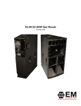
The X3 is a fully horn-loaded system, offering the utmost in efficiency for high SPL
applications. The system comprises two loudspeakers and a variety of flying hardware, all
designed to work together in an efficient manner.
a)
X3 three way tri-amplified high-Q loudspeaker
The X3 enclosure is a three-way fully horn loaded loudspeaker. Precise horn
loading techniques offer not just incredible efficiency, but highly predictable
coverage. As such, X3 arrays offer the user coverage angles that are directly
proportional to the number of elements in the array. The X3 boasts a wide
operating frequency range of 55Hz – 20kHz.
b) X3-DF downfill loudspeaker
The X3-DF is a two-way loudspeaker, utilizing the same midrange and high
frequency sections as the X3 system, and is intended for mounting directly below
X3 clusters to increase the vertical coverage angle of flown systems.
c) FC-X3 enclosure lifting beam
The FC-X3 is designed to mount between pairs of X3 enclosures for basic array
lifting. Up to four X3 enclosures can be safely suspended from a single FC-X3 with
a 10:1 safety factor.
d) MFB-X3 master flying beam
The MFB-X3 is required for X3 arrays which utilize more than one FC-X3 beam, yet
require a single pick-up point.
The X3 and X3-DF loudspeakers are designed and manufactured in our UK headquarters,
and rigorously tested before they leave the factory. All flying hardware is designed and
manufactured to exacting standards for both ease of use and user safety.
X3 User Manual
v1.0 May 2012
Page 6 of 29
3.0 – System Set up
Professional loudspeaker systems are potentially dangerous objects if used incorrectly.
Please ensure that you read this section fully, and contact EM Acoustics or your local
dealer should you be in any doubt over correct operation procedures.
Professional loudspeaker systems are capable of producing damage-inducing sound
pressure levels, and hence care should be taken when setting your system up, particularly
when it comes to loudspeaker placement within a venue. Damage to the ear can result
from levels above 90dB under prolonged exposure.
3.1 - Amplifier Selection
The X3 array element is designed to be used with professional power amplifiers providing
the following power outputs:
X3 LMF:
1200W/channel into eight ohms
X3 HMF:
400W/channel into eight ohms
X3 HF:
600W/channel into eight ohms
A small power amplifier working too hard is more likely to damage a loudspeaker than a large power amplifier
working within its operating range!
It is good practice to use an amplifier equal to the program power rating of the
loudspeaker – so as to retain sufficient headroom and good dynamic range. Care should
be taken during operation to avoid amplifier clipping – as this can cause serious damage
to your loudspeakers. If in doubt, please contact your dealer who will be happy to assist
you in correct amplifier choice and setup.
X3 User Manual
v1.0 May 2012
Page 7 of 29
3.2 - Cabling
X3 enclosures are supplied with Neutrik SpeakonTM NL8 connectors, wired in the following
manner:
Low Mid (15” drive unit):
pin 1+/1-
High Mid (8” drive unit):
pin 2+/2-
High (6 x 1” drive units):
pin 3+/3-
Pins 4+/4- are directly wired to pins 1+/1- on the NL4 connector on the rear panel of the
X3. This allows an additional feed to be sent down 8-core cables – either for subwoofers
or infills.
It is recommended that the resistance of your cable is less than one tenth of the nominal
system impedance.
Given below are the recommended maximum cable lengths for
different cross-sections and impedances.
Conductor Cross Sectional Area
4 ohms
Maximum Recommended Cable Length
8 ohms
16 ohms
1.0mm2
11m
22m
44m
1.5mm2
17m
34m
68m
2.0mm2
22m
44m
88m
2.5mm2
29m
58m
116m
4.0mm2
44m
88m
176m
6.0mm2
66m
132m
264m
X3 User Manual
v1.0 May 2012
Page 8 of 29
3.3 – DSP settings
As systems requiring multiple amplifier channels, both the X3 and the X3-DF require
external active processing to handle crossover points, system time alignment and
appropriate limiter settings.
The exact detail of the relevant DSP settings depends on the processor chosen, as well as
the amplifiers used as the limiter settings will vary depending on amplifier gain. As such,
please contact EM Acoustics directly for advice on appropriate DSP settings for your
system.
3.4 – The Drive Unit Test System
Incorporated into both the X3 and the X3-DF is a complete test system to give the user
the electrical status of all drive units within the enclosure.
Pressing the “test” button will engage a set of relay switches, which disconnect the drive
units from the amplifier feeds and instead connect them to the 9V battery powering the
test system. A green LED will light on the graphical representation of the front of the
loudspeaker for every drive unit with a complete electrical circuit. The “Battery OK” green
LED will also light.
Assuming the battery LED lights (if it doesn’t, replace the battery with a 9V PP3 type
battery), any LED’s not lit indicate an electrical issue with the associated drive unit. Check
the internal connections and if necessary replace the drive unit in question.
X3 User Manual
v1.0 May 2012
Page 9 of 29
4.0 – Flying & Stacking X3 systems
4.1 - System Overview
The flying system for the X3 product family has been specifically designed to be flexible,
intuitive and reliable. Please read this section of the user manual extremely carefully
as the rigging of loudspeakers is a very serious matter with potentially fatal consequences
should anything go wrong. If you are in ANY DOUBT WHATSOEVER, contact a
reputable rigging company or your local EM Acoustics representative.
IMPORTANT SAFETY CONSIDERATIONS
The X3 rigging system has been designed and constructed to a very high standard of
safety, and tested to demanding specifications. To ensure the highest standards of safety,
the following information on array assembly must be exactly followed and understood.
Only use EM Acoustics recommended rigging hardware and accessories, which are
specifically designed for the purpose. Do not use X3 flying hardware for any other
loudspeaker system – the components are specifically designed to work with the X3
system and are not interchangeable with any other EM Acoustics loudspeaker product or
any other loudspeaker system. The use of X3 flying hardware with other manufacturers’
systems may compromise the safety standards and EM Acoustics, and its parent company,
are in no way liable for any loss, damage or injury caused by such practice.
Do not modify or alter the X3 hardware or accessories, nor use them in any way other
than that described in this manual. Rigging components supplied as part of the X3 system
are in no way interchangeable and should not be used as such.
The component parts of the X3 rigging assembly should only be assembled in the manner
described in this manual, using the fasteners and fixings stated herein. The use of
fasteners and methods of assembly not described in this manual may result in an unsafe
assembly and as such EM Acoustics will not be responsible for any loss, damage or injury
caused by such practice. Welding, drilling or any other means of modifying any part of
the flying hardware or permanently fixing components to each other is strictly forbidden.
Rigging assemblies must only be assembled using the appropriate parts and fixings as
described in this manual, explicitly following the assembly instructions given herein.
Rigging components must only be fixed to EM Acoustics X3 system components, using the
correct cabinet location points, assembly methods and fasteners specifically described
within this manual.
Walls, floors and ceilings must be capable of supporting the actual load placed upon them.
The rigging hardware must be safely and securely fixed to both the loudspeaker system
and the supporting structure.
X3 User Manual
v1.0 May 2012
Page 10 of 29
When mounting components on walls, floors or ceilings ensure that all fixings and
fasteners used are of an appropriate size and load rating. Wall and ceiling claddings, and
the construction/composition of walls and ceilings also need to be taken into consideration
when determining if a given suspension method is safe.
4.1.1 - Secondary Safeties
It is best practice to ensure that all loudspeakers flown in any given environment should
be provided with a second, independent and properly rated safety suspension point in
addition to the principle load bearing means of suspension. Steel wire ropes or steel
chains of an approved construction and load rating only may be used as secondary
safeties. Plastic covered steel chains may not be used as secondary safeties under any
circumstances. Also ensure that all local and national laws are complied with when
determining your primary and secondary suspension points.
4.1.2 - Safety Inspections
Carefully inspect all flying system components prior to use for defects or signs of damage
prior to assembling an X3 array. If any components damaged or you suspect them to
be damaged, DO NOT USE THEM.
Regular scheduled tests – which are much more rigorous than visual inspections – of all
rigging components must also be carried out. Safety legislation, and test/inspection
requirements, will vary from country to country and as such it is the user’s responsibility to
ensure that local regulations are adhered to. In most cases, annual independent tests &
inspections carried out by a suitably approved and qualified inspector will be required.
EM Acoustics recommends detailed logbooks be kept of all inspections and load tests to
ensure an accurate record is kept of the testing for each EM Acoustics rigging accessory.
When flying any loudspeaker system, always wear protective headwear, footwear and eye
protection in accordance with local regulations.
The rigging of a flown loudspeaker system may be dangerous if not undertaken
by a suitably experienced and qualified rigger. Installation & fixing of all
hanging points should only be carried out by a professional rigger in
accordance with local legislation as well as the rules of the venue. The house
rigger and/or venue manager must always be consulted.
X3 User Manual
v1.0 May 2012
Page 11 of 29
4.1.3 - Safety Factors & Safe Working Loads
Safe working loads of the relevant rigging hardware is:
MFB-X3:
600kg with 10:1 safety factor
750kg with 8:1 safety factor
857kg with 7:1 safety factor
FC-X3:
400kg with 10:1 safety factor
500kg with 8:1 safety factor
570kg with 7:1 safety factor
X3 systems can be assembled with the following safety factors:
FC-X3 – Safety factor of 10
4 x X3 or X3-SP enclosure
FC-X3 – Safety factor of 7
4 x X3 or X3-SP enclosure
4 x X3-DF or X3-DFSP enclosure
MFB-X3 – Safety factor of 10
6 x X3 or X3-SP enclosure
2 x FC-X3 lift beams
MFB-X3 – Safety factor of 7
6 x X3 or X3-SP enclosure
6 x X3-DF or X3-DFSP enclosure
2 x FC-X3 lift beams
X3 User Manual
v1.0 May 2012
Page 12 of 29
4.2 – Ground Stacking X3 enclosures
When ground stacking X3 enclosures, the same hardware used to suspend them safely is
used to ground stack them securely. Each enclosure should be locked to the adjacent one
using both the top and rear rigging hardware systems (see section 4.4 steps 1 & 2), which
will make them much harder to move and therefore much more secure in their position.
Important notes to consider when ground stacking:
Ensure that the floor or stage surface can withstand the weight of the system.
Wherever possible, avoid high stacks. Please also remember that vibrations from
subwoofer systems can shake other loudspeakers out of place, which may present
a toppling hazard. The use of ratchet straps and non-slip material is recommended
to prevent this.
Whilst the X3 enclosures are locked securely together, please remember as noted above
that vibrations from subwoofers or adverse acts by artists/audience members could cause
the entire “block” of X3s to move. As such, it is strongly advised that the X3 elements –
even though they are locked together – have additional security in the form of ratchet
straps to secure them to the subwoofers or platform that they are positioned on.
X3 User Manual
v1.0 May 2012
Page 13 of 29
4.3 – The X3 Rigging System Components
The X3 flying system is designed to be very simple and intuitive to use. It is based around
three enclosure links, which are integral to each loudspeaker. Two of these links are
found recessed on the top of the loudspeaker, and are the primary load-bearing links.
The third link is recessed at the bottom rear of the enclosure, and is there to prevent
enclosures splaying apart at the bottom when the system is raised in the air.
Two optional additional flying hardware components are required – the FC-X3 enclosure
lift beam, and the MFB-X3 master flying beam.
4.3.1 – The FC-X3 enclosure lift beam
The FC-X3 is a simple lift beam, which is the primary method of flying X3 systems. At
least one FC-X3 will be required to fly X3 enclosures in any configuration.
Different flying hardware is required depending on
whether the requirement is for single or dual pickup point, and how many enclosures are used. The
images below illustrate the required hardware for
different configurations. A 3.25 ton bow shackle is
supplied with each FC-X3, and by moving the pickup point forwards or backwards the array angle
can be changed. For down-tilt, move the shackle
to the rear. For up-tilt, move the shackle towards the front.
For X3 arrays comprising multiple FC-X3 lift beams, if a single pick-up point is required
then the MFB-X3 master flying beam should be used to create a single rigging point. 3.25
ton shackles supplied with the MFB-X3 link with those on the FC-X3 lift beams to create a
secure lifting system.
MFB-X3 master flying beam
The tables in Appendix A on page 28 give the generated up or down-tilt angle
for different X3 array configurations. Please refer to these tables when
designing your X3 flown system.
X3 User Manual
v1.0 May 2012
Page 14 of 29
X3 User Manual
v1.0 May 2012
Page 15 of 29
Two X3 enclosures connected together
via the FC-X3 enclosure lift beam.
Three X3 enclosures
connected together
via two FC-X3
enclosure lift beams
and one MFB-X3
master flying beam.
X3 User Manual
v1.0 May 2012
Page 16 of 29
4.4 – Assembling Flown Arrays
Step 1 – Connect primary rigging links
The use of the WB-X3 transit wheelboard allows the enclosures to be positioned easily
prior to flying the system. Align the first two enclosures side by side, so their rigging
recesses line up. Release the ball-lock pin on each of the rigging assemblies (Item 1) and
lift the link up (Item 2) so it drops into the slot on the adjacent enclosure. Secure the link
with the ball-lock pin into the flying pin hole on the adjacent enclosure (Item 3). Repeat
this process for the second primary rigging link.
Step 2 – Rear rigging link
Remove the ball-lock pin at the rear of the enclosure (Item 1), and using the protruding
tab, flip the link (Item 2) into the slot on the adjacent enclosure. Secure the link in place
with the ball-lock pin (Item 3).
The first pair of X3 enclosures are now secured ready for flying hardware to be attached.
For arrays larger than 2 elements, repeat the above process until all enclosures are
securely fixed together.
X3 User Manual
v1.0 May 2012
Page 17 of 29
Step 3 – Attach FC-X3 enclosure lift beam
FC-X3 beams are required for flying,
regardless of the configuration. How many
beams and where in the array they attach
depends on the number of X3 elements
present, and whether 1 or 2 pick-up points
are required. See the diagrams above for
illustrations of the different combinations
possible.
The image to the right shows the two holes
on each primary rigging point where the
links on the FC-X3 engage. Insert the FCX3 into the slots and secure the Fc-X3 with
the four ball-lock pins attached to the FCX3, through the holes marked as shown (Item 1).
Two X3 enclosures connected together
via the FC-X3 enclosure lift beam.
X3 User Manual
v1.0 May 2012
Page 18 of 29
4.5 – Adding X3-DF downfill elements
The X3-DF and X3-DFSP are designed to swiftly, securely and safely mount below flown
X3 arrays to add additional vertical coverage to the system.
IMPORTANT NOTE: This procedure should be carried out by THREE people –
two to handle the X3-DF enclosure, and one to stabilize the flown X3 array.
The X3-DF has two rigging plates which secure it to the underside of the X3 enclosure.
On each of these plates are mushroom bosses – two on the front plate (Item 1) and one
on the rear plate (Item 2). The rear plate also includes the two ball-lock pins to secure
the X3-DF in place.
These bosses secure into the keyhole holes in the rigging plates on the underside of the
X3 enclosure. X3-DF enclosures should be installed from the FRONT of the array.
Step 1 – Prepare the X3-DF
Position the X3-DF at the front of
the flown array, in front of the
enclosure you wish to mount it
below. The person at the rear of
the array should remove the two
ball-lock pins from the back of the
X3-DF to ensure it is ready to be
installed (Item 3).
X3 User Manual
v1.0 May 2012
Page 19 of 29
Step 2 – Install the X3-DF enclosure
IMPORTANT NOTE: This procedure should be carried out by THREE people –
two to handle the X3-DF enclosure, and one to stabilize the flown X3 array.
One person should be at the front of the X3-DF, and one at the rear. The third person
should stabilize the X3 array to prevent it swinging. Lift the X3-DF enclosure up until the
mushroom bosses slot into the keyhole holes. Slide the X3-DF towards the back of the X3
array so that the mushroom bosses lock in place. Finally, reinstate the two ball-lock pins
to lock the X3-DF to the underside of the X3.
IMPORTANT NOTE: The last step of reinstating the ball-lock pins is VITAL.
Without these pins, the X3-DF is not secured and could fall from the array.
Repeat this procedure to add more X3-DF enclosures as required.
X3 User Manual
v1.0 May 2012
Page 20 of 29
5.0 - Servicing Information
All X3 and X3-DF components can be removed for service purposes if required, using the
minimum of tools.
X3/X3-SP enclosure - Removing LF Drive Unit
1. Place the enclosure on its top and remove the M6 socket cap screws securing the
access door on the underside. Gently lift the access door – please take care as
there is an EPS compression bung on the inside of the door which can get caught
on the mounting flange if care is not taken. Set the access door to one side.
2. Remove the six socket-head machine screws holding the LF drive unit in place.
Gently lift the drive unit approximately 6” out of its recess, disconnect the cables
and the driver can now be fully removed. Please make a note of drive unit polarity
for future reinstatement, as well as the rotation orientation as the drive unit will
only fit in the enclosure one way.
3. To re-install the drive unit, re-connect the cables observing the correct polarity and
then seat the drive unit in its recess. Rotate if necessary to ensure the drive unit
sits correcting within its recess. Re-instate the machine screws and re-tighten –
being careful not to overtighten. Replace the access door, and reinstate the
machine screws to hold the door in place.
X3/X3-SP enclosure - Removing the MF Drive Unit
1. Lie the X3 enclosure on its front so that the rear panel is easily accessible.
2.
A) On the X3 enclosure, remove the eight countersunk M6 machine screws around
the outside edge of the access door, and then the door can be removed. Once the
door is free, disconnect the two 2-way connectors and the one 12-way connector
which attach the drive units to the test circuit PCB. Set the door aside.
B) On the X3-SP, remove the eight socket-head machine screws around the
outside of the amplifier module fascia, and then the amplifier module can be
removed. Once the module is released, disconnect the two 2-way and one 12-way
connectors from the test circuit PCB. Set the amplifier module to one side.
3. Using a 13mm spanner or socket, undo the four M8 hex-head bolts securing the
rear sealing bowl for the midrange drive unit. Once the bowl is clear, reach inside
and disconnect the two spade terminals from the drive unit. The bowl can then be
completely removed from the enclosure.
4. Remove the eight M6 socket head bolts securing the 8” drive unit in place. The
drive unit can then be removed. Ensure you lift the drive unit straight up, as the
X3 User Manual
v1.0 May 2012
Page 21 of 29
phase plug protrudes towards the cone and sideways motion could damage the
cone surface. To re-install the drive unit, position the drive unit in place on the
moulding and carefully insert the eight M6 socket head machine screws. It is best
to start these bolts into their threads by hand, to avoid cross-threading. Once
these are tight, re-connect the cables via the spade terminals observing the correct
polarity (brown positive and blue negative) and then replace the midrange bowl.
Re-instate the M8 hex-head bolts and re-tighten – being careful not to overtighten.
IMPORTANT NOTE: Do not attempt to remove the midrange moulding from the
front of the X3 enclosure. The moulding is sealed in place and removing it will
break the seals.
X3/X3-SP enclosure - Removing the HF Array
1. Lie the enclosure on its back. Remove the M4 socket head machine screws (3 top,
2 bottom) and the eight Pozidrive screws (4 each side) that secure the grille, and
carefully remove the grille.
2. Remove the eight M6 countersunk machine screws securing the HF array
waveguide. Note that the four outer bolts are shorter than the four inner bolts.
Once the bolts are removed, gently lift the X3 waveguide moulding out of its
location.
3. Once the waveguide is removed, disconnect the cable assembly.
4. To reconnect the cables, note that the wiring orientation is critical. The X3 Array
label should point upwards when the box is upright, and the cables have the
correct length for each drive unit. Ensure polarity is also correct (white positive,
yellow negative).
5. To re-instate the HF array, position in place and gently press the moulding down
until it rests on its mounting flange. Ensure the cables are not caught up when
you reinstall. Replace the eight M6 bolts and retighten.
X3-DF/X3-DFSP enclosure - Removing the MF Drive Unit
1. Lie the X3-DF enclosure on its bottom so that the top access panel is easily
accessible.
2.
Remove the eight socket-head machine screws around the outside of the access
door, and then remove the door. Disconnect the cables from the drive unit
observing correct polarity.
3. Remove the eight M6 socket head bolts securing the 8” drive unit in place. The
drive unit can then be removed. Ensure you lift the drive unit away along the axis
of the waveguide, as the phase plug protrudes towards the cone and sideways
X3 User Manual
v1.0 May 2012
Page 22 of 29
motion could damage the cone surface. To re-install the drive unit, position the
drive unit in place on the moulding and carefully insert the eight M6 socket head
machine screws. It is best to start these bolts into their threads by hand, to avoid
cross-threading. Once these are tight, re-connect the cables via the spade
terminals observing the correct polarity (brown positive and blue negative) and
then replace the access door.
X3-DF/X3-DFSP enclosure - Removing the HF Array
1. Lie the enclosure on its back. Remove the Pozidrive screws (in the front and down
each side) that secure the grille, and carefully remove the grille.
2. Remove the eight M6 countersunk machine screws securing the HF array
waveguide. Note that the four outer bolts are shorter than the four inner bolts.
Once the bolts are removed, gently lift the X3 waveguide moulding out of its
location.
3. Once the waveguide is removed, disconnect the cable assembly.
4. To reconnect the cables, note that the wiring orientation is critical. The X3 Array
label should point upwards when the box is upright and also the angled sides of
the waveguide will follow the cabinet angles. The cables have the correct length
for each drive unit. Ensure polarity is also correct (white positive, yellow negative).
5. To re-instate the HF array, position in place and gently press the moulding down
until it rests on its mounting flange. Ensure the cables are not caught up when
you reinstall. Replace the eight M6 bolts and retighten.
X3 User Manual
v1.0 May 2012
Page 23 of 29
Appendix A – Array tilt angles
The tables below give the appropriate pick-up holes for the FC-X3 and MFB-X3 flying
hardware to give appropriate up or down-tilt angles.
The FC-X3 has ten pick-up holes, and for the purpose
of this data hole 1 is closest to the front of the FC-X3,
and hole 10 is the hole at the rear of the FC-X3.
In the tables below, the angle is shown for securing the shackle at the stated pick-up
point on a single FC-X3.
2 x X3 Enclosures, 1 x FC-X3 lift beam
4 x X3 Enclosures, 1 x FC-X3 lift beam
Hole
Hole
Angle
1
2
3
4
5
6
7
8
9
10
+10
+5
0
-5
-10
-15
-20
-25
-30
-35
Angle
1
2
3
4
5
6
7
8
9
10
+17
+12
+7
+2
-3
-8
-13
-18
-23
-28
X3 User Manual
v1.0 May 2012
Page 24 of 29
The MFB-X3 has twenty two pickup
holes, and these are numbered from the
outside of the beam (hole 1) to the
inside. The holes are mirrored – so hole
1 refers to the two outermost holes, and
hole 11 refers to the two innermost
holes.
When using two FC-X3 and a single MFB-X3, locate the shackles on the FC-X3 in the
appropriate hole for the desired angle, and then locate the MFB-X3 shackles in the stated
hole to ensure the two pieces of hardware can interface correctly.
3 x X3 Enclosures, 2 x FC-X3 lift beam
4 x X3 Enclosures, 2 x FC-X3 lift beam
Hole
MFB Holes
Hole
6
6
7
7
7
8
8
8
9
9
1
2
3
4
5
6
7
8
9
10
1
2
3
4
5
6
7
8
9
10
Angle
+11
+6
+1
-4
-9
-14
-19
-24
-29
-34
Angle
+9
+5
0
-5
-9
-14
-19
-24
-28
-33
MFB Holes
1
1
2
2
3
4
4
5
5
6
5 x X3 Enclosures, 2 x FC-X3 lift beam
6 x X3 Enclosures, 2 x FC-X3 lift beam
Hole
MFB Holes
Hole
6
6
7
7
7
8
8
8
9
9
1
2
3
4
5
6
7
8
9
10
1
2
3
4
5
6
7
8
9
10
Angle
+20
+15
+11
+6
+1
-4
-10
-15
-21
-27
Angle
+20
+16
+12
+7
+1
-3
-8
-13
-19
-25
MFB Holes
1
1
2
2
3
3
4
5
5
6
X3 User Manual
v1.0 May 2012
Page 25 of 29
Appendix B – Technical Specifications
X3 3-way horn loaded horizontal array element
ENCLOSURE TYPE:
DIMENSIONS (HxWxD):
NET/SHIPPING WEIGHT:
FREQUENCY RESPONSE1:
SENSITIVITY2:
DISPERSION3:
DRIVE UNITS:
POWER HANDLING:
MAXIMUM SPL4:
NOMINAL IMPEDANCE:
CROSSOVER:
CONNECTORS:
ENCLOSURE:
RIGGING & HARDWARE:
GRILLE:
OPTIONS:
ACCESSORIES:
SPARE PARTS:
three-way horn loaded
1111 (43.7) x 574 (22.6) x 859 (33.8) mm/(ins)
94/98kg (207/216lbs)
55Hz – 20kHz +/- 3dB
LF:
105dB
MF:
108dB
HF:
106dB
20H x 40V
15” (381mm) neodymium LF drive unit
8” (203mm) neodymium MF drive unit
6 x 1” (25mm) exit neodymium HF compression drive units
LF:
600W RMS, 1200W program
MF:
200W RMS, 400W program
HF:
300W RMS, 600W program
138dB continuous, 144dB peak
all frequency sections 8 ohms
external active
2 x Neutrik SpeakONTM NL8MPR, 1 x NLT4MP
15mm (5/8”) multi-laminate Birch plywood – rebated,
screwed & glued.
Finished in impact resistant textured paint
Integrated enclosure flying system
7 x steel bar handles
integrated drive unit test system
hex punched steel backed with acoustically transparent
foam
Colours/Weather Protection
FC-X3 enclosure lift beam
MFB-X3 master flying beam
TC-X3 padded touring cover
WB-X3 touring wheelboard
DU-1503 15” drive unit
DU-804 8” drive unit
CDU-1003 1” exit HF compression drive unit
RK-1503 recone kit
RK-804 recone kit
RD-1003 replacement HF diaphragm
RFG-X3 replacement grille/foam
X3 User Manual
v1.0 May 2012
Page 26 of 29
X3-DF 2-way horn loaded downfill element
ENCLOSURE TYPE:
DIMENSIONS (HxWxD):
NET/SHIPPING WEIGHT:
FREQUENCY RESPONSE1:
SENSITIVITY2:
DISPERSION3:
DRIVE UNITS:
POWER HANDLING:
MAXIMUM SPL4:
NOMINAL IMPEDANCE:
CROSSOVER:
CONNECTORS:
ENCLOSURE:
RIGGING & HARDWARE:
GRILLE:
OPTIONS:
SPARE PARTS:
two-way horn loaded
530 (20.9) x 574 (22.6) x 859 (33.8) mm/(ins)
37/39kg (81.4/85.8lbs)
200Hz – 20kHz +/- 3dB
MF:
108dB
HF:
106dB
20H x 40V
8” (203mm) neodymium MF drive unit
6 x 1” (25mm) exit neodymium HF compression drive units
MF:
200W RMS, 400W program
HF:
300W RMS, 600W program
134dB continuous, 140dB peak
all frequency sections 8 ohms
external active
2 x Neutrik SpeakONTM NLT4MP
15mm (5/8”) multi-laminate Birch plywood – rebated,
screwed & glued.
Finished in impact resistant textured paint
Integrated enclosure flying system
2 x steel bar handles
2 x flush handles
integrated drive unit test system
hex punched steel backed with acoustically transparent
foam
Colours/Weather Protection
DU-804 8” drive unit
CDU-1003 1” exit HF compression drive unit
RK-804 recone kit
RD-1003 replacement HF diaphragm
RFG-X3DF replacement grille/foam
Notes on measurement conditions:
1
Measured on-axis at 2m in an anechoic environment
and referenced to 1m.
2
Measured in half space at 2m with 4W sine wave input
and referenced to 1m.
3
Nominal dispersion, measured in an anechoic environment
and averaged over stated bandwidth
4
Calculated and verified by subjective listening test of familiar
program material.
X3 User Manual
v1.0 May 2012
Page 27 of 29
Appendix C – Spare Parts List
01A010
01A017
01B009
01C010
01C019
01D008
05A024
05A026
DU-1503
DU-804
CDU-1003
RK-1503
RK-804
RD-1003
X3_PIN
¼” x 1.1” PIN
15” neodymium LF drive unit, 8 ohms
8” neodymium MF drive unit, 8 ohms
1” exit neodymium HF drive unit, 16 ohms
8 ohm recone kit for DU-1503
8 ohm recone kit for DU-804
Replacement diaphragm for CDU-1003, 16 ohms
3/8” x 1.1” ball-lock flying pin with 6” lanyard
¼” x 1.1” ball-lock flying pin with 6” lanyard
X3 User Manual
v1.0 May 2012
Page 28 of 29
Appendix D – Warranty Information
Limited Warranty
This EM Acoustics loudspeaker product is warranted to the original end-user purchaser
and all subsequent owners for a period of three years from the original date of purchase.
Warranty Coverage
This warranty covers defects in materials and workmanship. It does not include:
Damage or failure caused by accident, misuse, neglect, abuse or modification by any
person other than an authorised EM Acoustics representative.
Damage or failure caused by operating the loudspeaker product contrary to the
instructions contained within this manual.
Damage caused during shipment.
Claims based on any misrepresentation by the seller.
Products which contain anything other than the original components (or EM Acoustics
factory supplied spare parts).
Products on which the serial number has been removed, altered or defaced.
Returning your EM Acoustics loudspeaker
Should your EM Acoustics loudspeaker develop a fault, please return it (freight prepaid) in
its original packaging, along with proof of purchase to your local dealer or to:
EM Acoustics (Returns Department), Building 74, Dunsfold Park, Cranleigh, Surrey, GU6 8TB, UK
including a description of the suspected fault.
Serial numbers must be quoted in all
correspondence relating to the claim. EM Acoustics or its representatives are in no way
liable for any loss or damage in transit, and hence it is recommended that the sender
insure the shipment. EM Acoustics will pay for return freight should the repair be covered
under warranty.
X3 User Manual
v1.0 May 2012
Page 29 of 29
EM Acoustics’ liability is to the replacement or repair (at our discretion) of any defective
components, and as such are not liable for any incidental and consequential damages
including (without limitation) injury to persons, damage to property or loss of use.
This warranty is exclusive and no other warranty is expressed or implied. This
warranty is also in addition to – and in no way detracts from – your statutory
rights as a consumer.
X3 User Manual
v1.0 May 2012