1
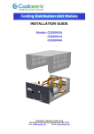
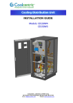
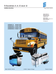
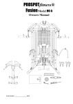
Rear Door Heat Exchanger Planning Guide Table of Contents 1. Planning for the Installation of the Rear Door Heat Exchanger (RDHx) 1 2. Related Documentation 1 3. Notices and Statements in this Guide 1 4. RDHx Components 2 5. Planning Considerations Overview 3 6. Water Specifications for the Secondary Cooling Loop 3 7. Water Delivery Specifications for the Secondary Cooling Loop 4 8. Layout and Mechanical Installation 9 9. Technical Support and Service 154 1. Planning for the Installation of the Rear Door Heat Exchanger This Planning Guide contains information for the installation of the Coolcentric LiquiCool® Rear Door Heat Exchanger (RDHx). The RDHx is a water-cooled door that is mounted on the rear of an IT Rack to cool the air that is heated and exhausted by devices inside the rack. Supply and return water hoses deliver conditioned water to the RDHx and remove the heated water from it back to the Coolant Distribution Unit (CDU) or chiller. In this guide, we refer to this as a secondary cooling loop. The primary cooling loop supplies the building chilled water to secondary cooling loops, air conditioning units and so on. The hoses, water treatment and CDU’s for the secondary cooling loop are not included with the RDHx and must be purchased separately from Coolcentric. The IT Rack on which you install the RDHx can be deployed on a raised floor or a non-raised floor. This document might be updated occasionally to include information about new features. Technical updates might be available to provide additional information that is not included in this documentation. These updates are available from the Coolcentric web site: http://www.coolcentric.com 2. Related Documentation The following documentation provides related information for the RDHx: Coolcentric LiquiCool Rear Door Heat Exchanger Installation and Maintenance Guide 3. Notices and Statements in this Guide The following notices and statements are used in this document: Note: Important: Attention: These notices provide important tips, guidance, or advice. These notices provide information or advice that might help you avoid inconveniences or problem situations. These notices indicate potential damage to programs, devices, or data. An attention notice is placed just before the instruction or situation in which damage could occur. Caution: These statements indicate situations that can be potentially hazardous to you. A caution statement is placed just before the description of a potentially hazardous procedure step or situation. Danger: These statements indicate situations that can be potentially lethal or extremely hazardous to you. A danger statement is placed just before the description of a potentially lethal or extremely hazardous procedure step or situation. 1 Rear Door Heat Exchanger – Planning Guide 4. RDHx Components The following components are required to install an RDHx unit to a Datacom Rack: 1. 2. 3. 4. 5. RDHx Door assembly RDHx hinge kit and door latch kit (ships with the RDHx) RDHx Documentation package (ships with the RDHx) Transition Frame (if required, ships with the RDHx) Air purging tool (sold separately). One air purging tool can be used to commission multiple RDHx doors. 6. Hose Kits (sold separately) 7. Water Treatment (sold separately) 8. Raise Floor Grommet (if a raised floor is used, sold separately) Figure 1 2 Rear Door Heat Exchanger – Planning Guide 5. Planning Considerations Overview High level planning considerations for the RDHx are as follows: 1. Provide non-condensing, treated water to the RDHx that meets the specifications as outlined in Section 6 – “Water Specifications”. 2. Provide a water delivery and distribution system that is suitable for your Data Center; recommended solutions are provided in Section 7 – “Water Distribution and Delivery”. 3. Provide floor tile cutouts on raised floors or protective coverings to avoid trip hazards on non-raised floors as part of the hose management. 4. Follow industry accepted best practices for airflow management, including but not limited to: use of rack mounted blanking panels, side panels for equipment enclosures, raised floor brush strips, hot aisle/cold aisle arrangement of equipment enclosures. 6. Water Specifications Water delivered to the RDHx must meet the requirements described herein to have optimal cooling performance and system reliability. Failure to meet these requirements may result in reduced capacity, leaks, or mechanical component failure. Supply water specifications include quality, temperature, pressure and flow. Deploying a closed secondary loop is typically the best way to easily meet these water specifications. Water should not be supplied directly from the building primary chilled water supply unless it meets all of the following requirements. 6.1) Water Quality Proper water treatment is essential to maintaining performance and reliability. The four challenges in water quality are corrosion, scaling, fouling and microbiological growth. 1. Corrosion degrades and pits the metal components within the RDHx and water distribution system; this can lead to leaks over time. 2. Scaling reduces heat transfer ability reducing cooling performance. 3. Fouling can block water flow through the system and impact performance. 4. Microbiological contamination can lead to all three issues previously listed. The water supplied to the RDHx must contain appropriate controls to avoid these issues. Particulate-free de-ionized (DI) water with corrosion inhibitors and biocides is the preferred approach to ensure quality requirements are met. Do not use DI water only; DI water without inhibitors is corrosive. 3 Rear Door Heat Exchanger – Planning Guide 6.2) Water Temperature Correct water temperature is critical to avoid condensation on the RDHx coil. Supply water must be maintained above the dew point of the data center to prevent condensation; it is recommended that water is supplied at 2°C (4°F) above the dew point to maximize cooling performance while providing an adequate buffer against changes in dew point. Failure to do so may result in condensation forming on the coil and water dripping onto the floor. Conversely, water temperatures significantly above dew point will reduce RDHx cooling performance. Typical building chilled water is supplied in the range of 5° to 7°C (41° to 45°F); this is normally below the dew point of most data centers, leading to condensation if supplied directly to the RDHx. If the water supply system does not measure room dew point and automatically adjust the water temperature accordingly, the minimum water temperature that must be maintained is 17°C (63°F). This is consistent with the ASHRAE Class 1 Environmental Specification that requires a maximum dew point of 15°C (59°F) in a data center. Refer to ASHRAE Thermal Guidelines Data Processing Environments at www.ashrae.org. 6.3) Water Pressure and Flow Rate The water pressure to the RDHx must be less than 690 kPa (100 PSI). Failure to do so may cause difficultly operating the quick connect couplings. Supply water flow rate is recommended to be in the range of 15 to 45 LPM (4 to 12 GPM). Higher flow rates will increase pressure drop in the system and pumping requirements and will not provide improved cooling performance. 7. Water Distribution and Delivery The distribution and delivery system consists of all the hardware necessary to provide water meeting the specifications in Section 6 to each of the RDHx in the data center. The recommended method is to have a closed secondary cooling water loop that is isolated from the primary loop. The primary cooling loop is considered to be the building chilled-water supply or a modular chiller unit. The primary cooling loop must not be used as a direct source of coolant for the RDHx unless it meets all of the Water Specifications. The secondary cooling loop consists of the piping, pumps and water-to-water heat exchangers that isolate the RDHx from the primary cooling loop while rejecting heat from the system. This section provides examples of typical methods for secondary cooling loop set-up. All components and services required for a successful RDHx deployment are available from Coolcentric. 7.1) Secondary Loop Materials The following materials are recommended for use within the secondary cooling loop: 4 Rear Door Heat Exchanger – Planning Guide 1. Copper 2. Brass with less than 37% zinc content 3. Stainless steel – 303, 304 or 316 4. EPDM (Ethylene Propylene Diene Monomer) rubber The following materials should be avoided in secondary cooling loops: 1. Oxidizing biocides, such as chlorine, bromine and chlorine dioxide 2. Aluminum 3. Brass with greater than 38% zinc 4. Iron and non-stainless steel 7.2) Manifolds and Piping Secondary distribution manifolds must be constructed of suitable materials and provide enough connection points to allow a matching number of supply and return lines to support the quantity of RDHx deployable, or planned to be deployed, within the data center. Piping must be sized appropriately to match the capacity rating of the pumps and water-to-water heat exchanger (between the secondary cooling loop and building chilled-water source). Anchor and support manifolds adequately to provide prevent strain on joints when quick-connect couplings are attached to or detached from the manifolds. In large manifolds shutoff valves are suggested to isolate sections of the manifold, preventing the flow of water in individual legs of a multiple circuit loops. This provides a way of servicing individual zones of the manifold without affecting the operation of the entire secondary loop. Temperature sensors and flow meters are suggested in secondary loop to provide assurance that water specifications are being met and that the optimum heat removal is taking place. Manifolds should have air vents, check valves and expansion tanks; individual component selection and placement will be site and application specific. The secondary cooling loop is a closed loop, with no continuous exposure to ambient air. After filling the loop, purge all air from the system. Air bleed valves are provided at the top of each RDHx for this purpose, however additional venting devices may be required if the RDHx is not the highest point in the system. Manifold systems should be pressure tested either on-site after installation or in the factory to ensure no leaks are present. 7.3) Flexible Hoses Flexible hoses are needed to supply and return water between the manifolds and the RDHx to allow movement when opening and closing the RDHx. Hoses should be made of EPDM rubber with quick-connect couplings at each end. Hose configurations and lengths can vary and are determined by analyzing the needs of your facilities; a Coolcentric site assessment service can 5 Rear Door Heat Exchanger – Planning Guide provide this analysis. Hoses longer than 15 meters (50 feet) may create unacceptable pressure loss in the secondary cooling loop and reduce water flow, thus reducing the heat removal capabilities of the RDHx. Verify that the CDU pumps are adequate to support the pressure drops in your system. Field supplied manifolds must have connections that are compatible with the flexible hoses, standard hose assemblies have 19mm (¾”) quick release couplings that comply with standard ISO 7241-1 Series B. Hoses with connections should be pressured tested after fabrication to ensure no leaks are present. 7.4) Examples of secondary loop configurations Figure 2 shows a typical cooling solution and defines the components of the primary cooling loop and the components of the secondary cooling loop. 6 Rear Door Heat Exchanger – Planning Guide Figure 3 shows an example of a facilities fabricated solution. The actual number of RDHx’s connected to the secondary cooling loop depends on the capacity of the CDU that is running the secondary cooling loop. Figure 4 shows an example of an off-the-shelf modular CDU. The actual number of RDHx’s connected to the secondary cooling loop depends on the capacity of the CDU that is running the secondary loop 7 Rear Door Heat Exchanger – Planning Guide Figure 5 shows an example of a typical central manifold layout that supplies water to multiple RDHx’s. Figure 6 shows another layout for multiple water circuits. 8 Rear Door Heat Exchanger – Planning Guide Figure 7 shows an extended manifold layout. 8. Layout and Mechanical Installation 8.1) This section provides an overview of the installation steps. The topics include the installation of the RDHx door on a raised floor environment (using tile cutouts) and a non-raised floor environment and hose management. For detailed information about installing a RDHx is see the Coolcentric LiquiCool Rear Door Heat Exchanger Installation and Maintenance Guide 8.2) Door Installation overview Installing the RDHx consists of the following tasks: 1. Prepare your facility to provide water to the equipment rack per the specifications in this document. 2. Remove the existing rack rear door and hinges and install the RDHx hinge assembly. 3. Attach the RDHx door to the hinge assembly. 4. Route flexible hoses, leaving enough length at the rack end to easily make connections to the RDHx terminations. 5. Connect the water supply and return hoses that run from the CDU or distribution manifold to the RDHx terminations. 6. Fill the RDHx with water. 9 Rear Door Heat Exchanger – Planning Guide 7. Adjust the hoses to ensure there are no kinks in the hoses and that the hoses are not lying against any sharp edges. 8. Adjust the door latch assembly to ensure the door fits flatly to the rack and the gasket seals to the rack. 8.3) RDHx filling and draining overview The following steps describe the requirements for draining and filling an RDHx: 1. Filling a RDHx with water requires the use of the air purge tool (sold separately) to purge any air from the manifolds 2. Draining the RDHx is recommended before it is removed from the enclosure or before the enclosure with an RDHx attached is moved. The air purge tool (sold separately) can be connected to the drain port on the bottom of the RDHx to drain the water. 3. Use absorbent materials under the work area to capture any water that might spill when filling or draining an RDHx. 8.4) Use on a Raised Floor environment On a raised floor environment, hoses can be routed under the floor tiles (using bottom-fed RDHx) or routed overhead (using top-fed RDHx). Each hose configuration and routing will be site and application specific and must be configured in a manner to allow for movement of the hose when the RDHx opens and closes without pinching or kinking the hoses. 1. When routing hoses overhead using a top-fed RDHx, straight hoses or right angle hoses may be used. It is recommended that cable trays be used to support the entire length of hose as it is routed overhead. The trays must be able to support the weight of the hoses when filled with coolant. For planning purposes use 4kg (9lbs) per 3m (10 foot) of hose supported. For example a tray with 6 hose kits (12 hoses total), each 6 meters (20 feet) long must be capable of supporting at least 96kg (216lbs). All cable trays or similar must be installed per local and national code requirements. 2. When routing hoses under raised floor tiles using a bottom-fed RDHx, straight hoses or right angle hoses may be used. The bottom-fed RDHx requires a cutout in the 600mm x 600mm or 24” x 24” floor tile behind the enclosure when using straight hoses. The cutouts in the raised floor tiles should be properly sealed with raised floor grommets to prevent air leakage and cover sharp edges. The corner of the cutout is placed directly under the hinge side of the enclosure rear door. The opening of the cutout is recommended to be at least 152mm wide x 190mm long (6” x 7.5”) in the direction parallel to the RDHx. See Figures 8 and 9. Please note stringer-less raised floors may not be able to use this method. 10 Rear Door Heat Exchanger – Planning Guide 11 Rear Door Heat Exchanger – Planning Guide 3. For enclosures being installed at the same time as an RDHx, or in cases where the cutout cannot be placed directly beneath the RDHx, a modified cable opening hose cutout can be used. Hoses with a right-angle elbow can be used to route the hoses under the enclosure in a large loop to allow hose movement when the door is opened and closed, and then fed into the cutout positioned fully under the enclosure. Figures 10 and 11 show an example of this. Existing floor tile cutouts for electrical or other cables can also be used for the hoses if enough space is available. 12 Rear Door Heat Exchanger – Planning Guide 4. Lay hoses side-by-side as they run between the RDHx and the external manifold or CDU manifold and allow the hoses to freely move. Leave enough slack in the hoses below the RDHx so that no pressure is exerted on the mated couplings when the hoses are attached and operating. When routing hoses, avoid sharp bends that cause hose kinks and avoid hose contact with sharp edges. 8.5) Use on a non-Raised Floor environment On a non-raised floor environment, hoses can be routed between the RDHx and floor (using bottom-fed RDHx) or routed overhead (using top-fed RDHx). Each hose configuration and routing will be site and application specific and must be configured in a manner to allow for movement of the hose when the RDHx opens and closes without pinching or kinking the hoses. 13 Rear Door Heat Exchanger – Planning Guide 1. When routing hoses overhead using a top-fed RDHx, straight hoses or right angle hoses may be used. It is recommended that cable trays be used to support the entire length of hose as it is routed overhead. The trays must be able to support the weight of the hoses when filled with coolant. For planning purposes use 4kg (9lbs) per 3m (10 foot) of hose supported. For example a tray with 6 hose kits (12 hoses total), each 6 meters (20 feet) long must be capable of supporting at least 96kg (216lbs). All cable trays or similar must be installed per local and national code requirements. 2. When routing hoses between the RDHx and the floor using a bottom-fed RDHx, right angle hose kits are typically required. Straight hose assemblies cannot make the sharp bend to exit between the floor and the RDHx without kinking the hoses. Using right angle hose assemblies with metal elbows allows the hoses to be routed along the floor, make a 90o turn upwards within the gap between the bottom of the RDHx and the floor surface and then connect to the supply/return couplings. This is shown in Figure 12. 3. Hoses exiting the RDHx are routed in a manner similar to that of power cables in a non-raised floor Data Center. For example, place the hoses side-by-side and allow them to move freely as they approach the enclosure (within approximately 3 meters or 10 feet of the enclosure). 14 Rear Door Heat Exchanger – Planning Guide When the door is opened, it is acceptable for the hoses to move slightly and rotate in parallel at the coupling interface inside the door. As the door is closed, the hoses rotate back to their original positions. When opening or closing the door, some manipulation of the hose along the floor might be necessary to prevent unwanted forces on the door and to make it easier to open and close the door. 9. Technical Support and Service To obtain technical support or service please contact Coolcentric directly at: Toll-free (US/Canada): +1 877.248.3883 DDI: +1 508.203.4690 Email: [email protected] 15 Rear Door Heat Exchanger – Planning Guide The LiquiCool Rear Door Heat Exchanger is patented by Vette Corp – Pat. 7,385,810 ©2010 Coolcentric, a Division of Vette Corp Part # 104780 Rev C 16 Rear Door Heat Exchanger – Planning Guide