1
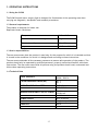
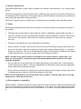
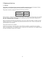
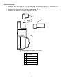
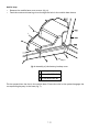
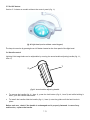
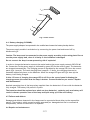
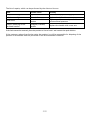
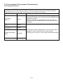
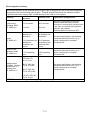
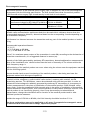
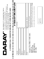
® SL300 Ceiling, Wall and Mobile Version INSTALLATION AND OPERATING MANUAL QAM.SL300.0909.4 2 ® 1 OPERATING INSTRUCTIONS 1.1 USING THE SL300 1.2 GENERAL REQUIREMENTS 1.3 USER’S RESPONSIBILITIES 1.4 TECHNICAL DATA 1.5 DESCRIPTION OF THE ELEMENTS AND FUNCTIONS 1.6 DESIGN CHARACTERISTICS 1.7 SAFETY 1.8 ELECTROMAGNETIC COMPATIBILITY 4 4 4 4 5 7 7 7 2 SHIPPING AND START-UP 2.1 SHIPPING 2.2 UNPACKING AND INITIAL START-UP 2.3 INSTALLATION AND START-UP 2.4 CONTROL PANEL 2.5 ON/OFF SWITCH 2.6 HANDLE CONTROL 2.7 POSITIONING 8 8 9 10 14 15 16 3 CORRECT OPERATION ASSESSMENT CRITERIA 17 4 TECHNICAL SUPPORT 4.1 STORING 4.2 WASHING AND DISINFECTION 4.3 CHANGING THE LIGHT BULB 4.4 BATTERY CHARGING (RELATES TO MOBILE). 4.5 FAILURES AND DEFECTS 4.6 REPAIRS AND MAINTENANCE 4.7 TECHNICAL INSPECTIONS AND CHECKS 4.8 TROUBLESHOOTING 18 18 18 19 20 20 21 21 22 5 ELECTROMAGNETIC ENVIRONMENT CHARACTERISTICS 23 RETURNS POLICY 26 WARRANTY 27 WARRANTY REGISTRATION 29 Tel: 0844 375 9000 Fax: 0333 321 0973 email: [email protected] url: www.daray.co.uk 3 1. OPERATING INSTRUCTIONS 1.1 Using the SL300 The SL300 Illumin8 minor surgery light is designed for illumination of the operating area when carrying out diagnostic, therapeutic and cosmetic procedures. 1.2 General requirements The product is designed for indoor use. Required climatic conditions: Temperature 10°C to 40°C Ambient temperature change over 8 hours not greater than 20°C Relative humidity 30% to 80% Air pressure 700 hPa to 1060 hPa. 1.3 User's responsibilities The user must ensure that the product is used only for the purpose for which it is intended and that it is used in the conditions for which it is designed and according to these instructions. The user must undertake all the necessary measures to ensure safe operation of the product. The product should only be operated by qualified personnel, properly trained and familiar with these instructions. The user must ensure that all persons using the product should read, understand and follow these operating instructions. 1.4 Technical Data LIGHT INTENSITY 35 000 ± 5000 lx 50 000 ± 5000 lx COLOR RENDERING INDEX (Ra) 96 ± 1 90 ± 1 OPERATING FIELD DIAMETER 13-19 ± 2 cm COLOR TEMPERATURE 4200 ± 200 K IRRADIATION INTENSITY EE (AT ECMAX) 189 W/m 2132 W/m2 OPERATING RANGE WITHOUT FOCUSING 70 – 140 cm POWER SUPPLY 230V, 50/60 Hz LIGHT SOURCE Halogen lamp 22.8 V 50 W LAMP LIFE 1300 h ILLUMINATION CONTROL 50 – 100% 4 1.5 Description of the elements and functions 4 3 5 1 fig.1 SL300W Illumin8 minor surgery light 1 Light-head 2 Autoclavable adjusting handle 3 Lamp positioning arm 4 Lamp suspension arm 5 Wall mounting 5 2 3 6 2 5 4 fig.2 SL300M Illumin8 minor surgery light 1 Light-head 2 Autoclavable adjusting handle 3 Lamp positioning arm 4 Stand 5 Control panel 6 Lamp suspension arm 6 1 1.6 Design characteristics The SL300 Illumin8 minor surgery light is designed for ceiling or wall-mounting, or as a mobile lamp device. The lamp is designed to ensure excellent colour rendering, high intensity and uniform distribution in the operating field. Suspension of the lighting fittings and the handle on the lamp ensure stable and easy positioning adjustment during operation. The SL300 is supplied with a variable-focus controlled by the removable, auto-claveable handle. 1.7 Safety Following the guidelines and instructions included in this manual assures safe operation and use of the product. • The lamp may only be used for the purpose for which it is designed, as specified in section 1.1. • Incorrect operation of the lamp operating principles could be hazardous. Failure to observe the instructions in this manual could result in a hazardous situation and may invoke the product warranty. • The lamp is not designed for use in hazardous environments. • When the lamp is turned on do not look at the front part of the lamp, as glare effect may occur. • Do not use the lamp, when the occulters or optical filter system indicates failure i.e. unstable fastening, cracks etc. There is a considerable disturbance of temperature conditions and change of light characteristics, which can largely affect the medical procedure. NOTE: Changes in the optical system incorporated in the lamp (reflector, optical filter, and bulb) are unacceptable; changing the type of the optical system elements will result in loss of light properties of the lamp. • Do not install any foreign elements (not supplied by Daray) on the lamp case, inside the lamp, on the clamping arm system, as this may destabilize the suspension system and pose additional hazard when performing the operation. • Avoid collision with both the clamping arms and the lighting fixtures. Multi-collisions may result in damage and loss of proper technical parameters by the lamp. NOTE! During lamp operation do not touch the front occulters. The glass may heat up to a high temperature, which may cause burns. 1.8 Electromagnetic compatibility Medical product: SL300 Illumin8 minor surgery light is an electrical device. Electrical devices are the source of electromagnetic radiation and are affected by it. However, the SL300 operates from 50Hz mains and is neither a significant source of EM radiation, nor is likely to be significantly affected by it. 7 2 Shipping and start-up 2.1 Shipping The product can be shipped by any commonly available covered type means of transport. During transport the unit should be protected from moisture and locked in place. The product should be transported under the following conditions: Temperature 10°C to 60°C Relative humidity 20% to 80% During transport, storage and unpacking of the product, the temperature change may not be greater then 10°C during one hour. The product can be unpacked only after reaching the temperature of the room, where the product is located. When the difference between the temperature of the room, where the product is located, and the shipping temperature is considerable, the product should be left for min. 12 hours. Only after this time the device can be started. This product should not be stacked. Should it be necessary to ship the product under different conditions, especially when shipping under low temperatures, it is necessary to prior arrange with the manufacturer the shipping method and type of package to ensure safe Transport. 8 2.2 Unpacking and initial start-up The lamp is supplied by the manufacturer as a disassembled unit in a cardboard box. The lamp should be unpacked inside the building to protect it from being damaged. In order to prepare the lamp for service after delivery or shipment: • remove securing tapes • remove the cardboard cover Remove transport packing from the lamp. Packing waste is recyclable material and should be disposed of accordingly. The packages may have the following markings: reusable package recyclable package low-density polyethylene package LDPE Fasten the lamp clamping arm system according to the lamp version; spring arms allow to adjust the angle of deflection and tension (the deflection angle and tension adjustment system is located below the removable arm casing), Secure the lamp in the arm holder. Carefully read the operating instructions of the product. Perform the initial start-up of the product according to the description provided in section. 9 2.3 Installation and start-up. Before beginning with installation of the lamp with the suspension system visually check the delivered product. This applies in particular to cracking of the optical filter system and lamp covers and autoclavable handle fastening. The SL300 is supplied by the manufacturer disassembled. Depending on the model, the SL300 consists of the following parts: • • • SL300C - light-head, supporting arms system, ceiling mounting system; SL300W – head of the lamp, supporting arms system, wall holder; SL300M – head of the lamp, stand, and mobile base. Assembly of above mentioned parts should be performed according to given instructions. Ceiling lamp Assembly the ceiling plates according to instructions given in “Instruction for building preparation for installation of operation and examination lamps” Assembly the supporting arms system to ceiling mounting system (fig.3), Assembly the head of the lamp to spring arm (fig.4). 1 1 2 3 4 3, 4, 5 2 fig.3 Assembly of supporting arms system to ceiling plate fig.4 Assembly of head of the lamp to spring arm 1 Ceiling plate 1 Masking cover 2 Supporting arms system 2 Screw blocking the covers 3 Nut M12 PN-86/M-82144 3 Protecting plate 4 Washer A13 DIN 125 4 Ending of lamps arm 5 Washer Al2 DIN 127 10 Wall-mounted lamp • • • Assembly the wall holder to the wall according to instructions given in “Instruction for building preparation for installation of operation and examination lamps” Assembly the supporting mars system to wall holder (fig. 5), Assembly the head of the lamp to spring arm (fig. 4). 5 4 2 3 1 fig.5 Assembly of the arm to wall holder 1 Wall holder 2 Supporting arm 3 Washer 4 Ending of lamps arm 5 Cover 11 Mobile lamp • • Remove the mobile base cover screws (fig. 6) Feed the mains and steering wires through the hole in the mobile base sleeve 3 1 2 fig.6 Assembly of the battery backup cover 1 Battery backup cover 2 Screw M3x25 DIN 963 3 Screw M3x6 DIN 963 Fit the upstand into the slot in the mobile base. Ensure the slot in the upstand engages the corresponding keyway in the base (fig.7) 12 1 2 3 4 fig.7 Assembly of the lamps stand 1 Stand 2 Moveable base of the lamp 3 Leasing pin 4 Output of the wires 1 2 3 fig.8 Assembly of the screw blocking the stand Secure the upstand with the screw fitted from beneath the base (fig. 8) 1 Stand assembly washer 2 Washer A10 DIN 127 3 Screw M4x6 DIN 963 13 Connect the mains and control wires, Assembly the mobile base cover screwing the screws (fig. 6), Assembly the head of the lamp to spring arm (fig. 4), Connect the mains wires. After assembly of examination lamp one should connect the power supply lead to mains 230V (according to “Instruction for building preparation for installation of operation and examination lamps”). Check the light operates in accordance with the functions defined below. Ensure all controls operate smoothly Do not put the product into service unless it operates properly in accordance with this manual. The manufacturer will not accept liability for any outcome whatsoever from customers’ assembly or use of this product where the content of this manual has not been fully observed Use and operation 2.4 Control panel Section 3.1 refers to mobile version of the lamp (fig. 2) 1 2 4 3 5 6 fig.9 Layout of the function keys on the control panel The control panel is located on the stand. After connecting to the mains, the green LED (2) lights. The lamp is switched on by pressing the button "I" (1) Lamp parameters are set using buttons (3) and (4), which can be used to control light intensity within a range from 50 to 100% Ec. The lamp is switched off by pressing the button (1). Indicator (5) shows the battery charge state, and the LED lighting up next to the indicator (6) indicates battery charging process. LED indicators on the control panel LED No. on 2 meaning Yes lamp power on no lamp power off 5 Yes indicates the battery charge level 6 Yes battery charging in progress 14 2.5 On/Off button Section 3.2 relates to models without the control panel (fig. 1) fig.10 Light-head (version without control keypad) The lamp is turned on by pressing the on/off button located on the front panel of the light-head. 2.6 Handle control Lighting field magnitude can be adjustable by turning the autoclavable adjusting handle (fig. 11, item 1). 1 2 fig.11 Autoclavable adjusting handle • To remove the handle (fig.11, item 1), press the lock button (fig.11, item 2) and while holding it down, pull the handle downwards. • To install the handle slide the handle (fig.11, item 1) onto the guide until the latch locks in place. Before each use, check if the handle is undamaged and is properly fastened. In case of any malfunction, replace the handle. 15 2.7 Positioning Light-head positioning is done using the autoclavable adjusting handle (fig.11 item 1). Lamp height is adjusted by moving the suspension arm (fig.12 and 13). It is possible to adjust the arm tension. To reduce the tension (arm rises) insert the adjusting bar (located below the removable casing) in the hole and rotate clockwise (-). If the tension is too small (arm drops), rotate the adjusting bar anti-clockwise (+). fig.12 Adjusting the arm tension for SL300M and SL300MB 16 fig.13 Adjusting the arm tension for SL300W and SL300C 3. Correct operation assessment criteria The product should be checked for correct functioning before its first start-up on the particular day. Correct operation assessment procedure: 1. Check if the lamp moves smoothly by manually moving the lamp 2. Check if there is no mechanical backlash when moving the lamp and the arm 3. Check functioning of the electronic system by executing all movements controlled from the control panel and the sterilised handle. If the lamp passes the tests described above and if during the functional movements no distressing sounds (creaking, rasps) are observed, then the product can be safely used. Otherwise refer to section 5.7 Troubleshooting. If the product is not fully functional, i.e. the obtained parameters deviate from the specification provided in these instructions, do not attempt to operate it. If this is a case, report it to the manufacturer or the supplier (dealer). NOTE: Using unserviceable product may lead to consequent damage, with expenses charged to the user, and for which the manufacturer assumes no liability. 17 4. Technical Support 4.1 Storing If the product is not going to be used for long time, store it under the following climatic conditions: Temperature 25° ±100° ±10°C, Relative humidity 50% ± 25%. 4.2 Washing and disinfection When washing and disinfecting use washing agents, which do not contain bleaching agents (active oxygen or chlorine). After disinfecting the product must be washed out with distilled water to eliminate weeping. Using too much water can lead to flooding the interior of the lamp. After disinfecting dry the product completely. Dry it with hot air (max. temp. to 60°) or by wiping with a soft sterile cloth. Autoclavable handle Removable adjusting handle (item. 1, fig. 6) is made of material resistant to high-temperature sterilisation conditions. The handle must be washed/cleaned, disinfected and sterilised, before the first use and before each next use. Make sure to use for washing/cleaning and disinfection, only the agents which are intended for this purpose. The handle should be sterilised in autoclave at a temperature up to 134°C for max. 5 minutes. During sterilisation observe the parameters specified by the autoclave manufacturer. The lamp must be cleaned and disinfected immediately after its use. Washing/cleaning and disinfection operations should be to carried out according to the instructions of the manufacturer of agents used, paying particular attention to the agent concentration, method of carrying out the operation and recommended disinfection time. Only handles, which have been prior cleaned and disinfected, can be sterilised. The handle should be sterilised in standing position due to possible collection of water inside the component. The handles can be sterilised maximum 1000 times, after this time the handles should be replaced with new ones. Light-head, supporting system Plastic dishes should be washed/cleaned and disinfected. CAUTION: The light is not waterproof. 1) Do not use bleaching (containing active chlorine or oxygen), caustic or corrosive agents. 2) Do not use agents together with plastics, which can cause damage to network structure of the plastic elements (organic solvents). Failure to comply with the above requirements will void the products guarantee. 4.3 Changing the bulb 18 Only original spare bulbs supplied by Daray may be used. Using other bulbs may lead to reduction of light intensity and adverse changes in optical and heat parameters. Halogen bulb life is approx. 1300h. Bulb must be changed in the following sequence: • • turn off the lamp, unscrew the cover (item.1, fig.7) Caution: After turning off the lamp, the light-head, internal structural elements and bulbs can remain hot. 1 Fig.14 Bulb holder cover 1) unscrew the knurled screw (item.2, fig.9), remove the bulb holder (item.3, fig.89,) Do not touch the new halogen bulb with bare hand. To grab it use the original package or clean material. 1) mount the new bulb (item.5, fig.15) supplied by Daray Ltd in its socket (item.4, fig.15), 2) Tighten up the cover proceeding in the reverse sequence. 19 1 2 3 4 5 Fig.15 Bulb holder 4.4. Battery charging (SL300MB). The power supply adapter incorporated in the mobile base houses the battery backup device. The power supply module is switched on by connecting the power lead and turned off by disconnecting it. Caution: The lamp must be connected to the power supply according to the rating plate! Do not use the power supply lead, when it is faulty or the insulation is damaged! Do not connect the lamp in areas presenting risk of explosion! In order to charge the batteries connect the mains lead to the power supply network 230V 50/60 Hz. Connection to the power supply is indicated by green LED on the control panel. The batteries are charged automatically. The charging process is signalised by the orange LED lit on the control panel fig.4. item.(6). The total charging time is approx. 12 hours, the charging time can be extended without any harm to the batteries. When the orange LED goes off fig.4 item.(6) the battery is still being charged. If after 12 hours of charging the orange LED is still lit on the control panel indicating the charging process this means that the lamp is broken. Proceed further as per section "Repairs and maintenance". Nominal operating time of the lamp when supplied from the batteries is 2 hours with the batteries fully charged. The battery life period is 5 years. The batteries should be replaced as a whole set (two batteries), replacing only one battery will result in shorter operation time of the lamp and quick using up of the new battery. 4.5 Failures and defects Damages and defects detected in the lamps must be reported without delay to the responsible person. The product, which cannot be safely operated (ex. damaged electrical or mechanical components), cannot be used until it is repaired. 4.6 Repairs and maintenance 20 Repairs must be carried out by the manufacturer or an authorised repair centre. The user may not carry out any repairs or modifications to the product. In order to assure safe and reliable operation of the product, use only original spare parts supplied by the manufacturer. The used parts must be disposed off in compliance with the applicable environmental protection provisions. This product contains components, which may be dangerous to the environment. Methods of disposal of used products, which may be hazardous to the environment, are governed by the waste disposal provisions. If the batteries need to be replaced, the used batteries are collected by the medical equipment manufacturer or the authorised repair centre indicated by it. Repairs and maintenance must be carried out only by qualified personnel. 4.7 Technical inspections and checks To ensure safety and proper technical condition of the product, within the whole period of product serviceability, the product must be subjected to periodical technical inspections performed at the user's expense by the manufacturer, authorised repair centre or Client's authorised trained technical personnel. Only the satisfactory result of the inspection may form the base for further use of the product. The user must perform periodical technical inspections according to the table below. Scope of the inspection Frequency checking the functionality and general technical condition (according to the service instructions) every 12 months Technical inspections should be recorded on the repair list supplied with the Guarantee Card of the product. The user should carry out technical checks every 6 months according to the table below. The scope of technical check 1) 2) 3) Checking correct connections and protections in the rotary points, adjusting the pressure of friction brakes, which ensure stable operation of the suspension system, Checking the electrical safety (visual inspection of the insulation condition of the power leads). Supporting arms 1) Sterilised handle Light-head 2) 1) 2) Checking by visual inspection the technical condition of the handle surface, no cracks, scratches etc. Checking proper functioning of the securing mechanism of the sterilised handle, Checking the front polycarbonate panel, no cracks, scratches etc., Checking correct functioning of the control systems (control panel, sterilised adjusting handle). 4.8 Troubleshooting 21 The list of repairs, which can be performed by the client on his own Fault Possible cause Remedy Lamp does not light No power Check the lamp power supply system Bulb does not light Blown bulb Replace the bulb with a new one. Loose bolts Intensive use of the product Tighten up with commonly available constructional spanners Insecure fastening of the sterilised handles Damaged (cracked) handles Replace the handle with a new one If the fault cannot be removed, place the product as "out of order" and contact the repair division. If the customer resigns from further using the product, he will be responsible for disposing of the product in accordance with the provisions of the Environmental Protection. 22 5. Electromagnetic Environment Characteristics Electromagnetic emissions Medical product: SL300 Illumin8 minor surgery light is designed for use in the electromagnetic environment with the following specification. The User should ensure that the medical product: SL300 Illumin8 minor surgery light is used exactly in this kind of environment. Type of emission Classification Explanations and guidelines RF emissions CISPR 11 Group 1 The medical product: SL300 Illumin8 minor surgery light generates RF energy only for internal needs required by the equipment to work. The level of the RF energy emission is very low and it is unlikely to cause any interference with the near electronic equipment. RF emissions CISPR 11 Class B Harmonic emissions IEC 61000-3-2 A Class Voltage fluctuations, flicker Compliant The medical product: SL300 Illumin8 minor surgery light is designed for use in habitats and in rooms directly connected to LV network, which feeds residential buildings. IEC 61000-3-3 23 Electromagnetic immunity The medical product: SL300 Illumin8 minor surgery light is designed for use in the electromagnetic environment with the following specification. The User should ensure that the medical product: SL300 Illumin8 minor surgery light is used exactly in this kind of environment. Immunity Electrostatic discharge (ESD) IEC 61000-4-2 Surges IEC 61000-4-5 Series of fast transient states IEC 61000-4-4 IEC 60601-1-2 Test level Immunity level ± 6 kV contact ± 6 kV contact ± 8 kV air ± 8 kV air ± 1 kV between the ± 1 kV between the Feeding line Feeding line conductors conductors ± 2 kV between the feeding line Conductor and ground ± 2 kV between the feeding line conductor and ground Explanations and guidelines The floor in the place of using the product should be made of wood, concrete or covered with ceramic tiles. If the floor is covered with synthetic material, the relative humidity should be minimum 30% The mains specification and existing interference should be such, as in typical commercial or hospital environmental ± 2 kV feeding lines ±2 kV lines feeding The mains specification and existing interference should be such, as in ± 1 kV signalling ±1 kV signalling typical commercial or hospital lines lines environmental. < 5% UT (>95% dip UT) for 0.5 cycle Voltage drops, collapses, voltage fluctuations in feeding lines IEC 61000-4-11 The mains specification and existing interference should be such, as in typical commercial or hospital environmental. 40% UT (60% dip UT) for 5 cycles 70% UT (30% dip UT) for 25 cycles < 5% UT (>95% dip UT) for 5 secs NOTE UT is a mains voltage before applying the test voltages 24 Electromagnetic immunity The medical product: SL300 Illumin8 minor surgery light is designed for use in the electromagnetic environment with the following specification. The User should ensure that the medical product: SL300 Illumin8 minor surgery light is used exactly in this kind of environment. Immunity IEC 60601-1-2 Test level Immunity level Conducted 3 Vrms Interference induced by RF fields IEC 61000-4-6 150 kHz to 80 MHz 3 Vrms Electromagnetic RF field IEC 61000-4-3 3 V/m 3 V/m 800 MHz to 2.5 GHz Explanations and guidelines Portable radio communication appliances should not be used within a distance shorter than the recommended separation distance, determined based on the corresponding formula depending on the transmitter frequency. This distance is a distance between the transmitter and any part of the medical product or/and its wiring. Recommended separation distance: d =1,21 √ P d =1,2 √P 80 MHz to 800 MHz d = 2,3, √P 800 MHz to 2.5 GHz Where P is a maximum power output of the transmitter in watts ON) according to the declaration of transmitter manufacturer; d is a suggested distance in meters (m). Intensity of the fields generated by stationary RF transmitters, determined based on measurements taken at the installation site ' should be less than the level of immunity of The column within the whole frequency range. b Malfunctioning of the medical product can occur when using the column near the equipment marked with the following symbol. The user should check correct functioning of the medical product, when being used near the equipment marked with this type of symbol (I) Intensity of the fields generated by stationary transmitters, such as radio and telephone stations (wireless/cellular telephony), ground mobile radio stations, amateur radio stations, AM FM transmitting stations, TV transmitters, cannot be estimated with sufficient precision. In order to evaluate the electromagnetic radiation generated by stationary RF transmitters it is necessary to conduct measurements in the place of installation of the medical product: SL300 Illumin8 minor surgery light. If the electromagnetic field strength value in the place of installation of the medical product exceeds its immunity level, then correct operation of the product should be verified. If the medical product is not functioning properly, then it may be necessary to take additional measurements, change the orientation and/or location of the medical product and/or take additional protective measures. Outside the range of 150 kHz to 80 MHz, the field intensity should be less than 3 V/m. The above explanations may not be applicable to all cases. Propagated electromagnetic waves are absorbed and reflected from buildings, objects and people. 25 Returns Policy IMPORTANT! Before returning your item, you must call us on 0844 375 9000 We want you to be completely satisfied with your purchase. If you need to return goods purchased from DARAY Ltd, please read the following information carefully. The DARAY Ltd returns policy provides guidance on when you can return goods we have supplied, and what you can expect from us once you do. To see our detailed returns policy and procedure visit www.daray.co.uk/returns TYPE OF RETURN REMEDY DAMAGED GOODS OR DOA* Goods which are physically damaged on delivery, or which do not function. We must be notified within 24 hours of receipt. Within 14 days of delivery we will replace the item as GOODS DEVELOPING A FAULT DOA*. Goods which have developed a fault within If the fault develops after 14 days, but within the the warranty period. warranty period, we will initiate the returns procedure. NON WARRANTY Goods which have developed a fault outside the warranty period. If a fault develops outside the warranty period, we will initiate the returns procedure. OTHER Any situation which is not covered by the above. We will try to help, but we cannot normally offer a refund. *DOA – dead on arrival For additional clarification, please refer to our terms and conditions at www.daray.co.uk/terms. In a small number of cases, we may determine that a replacement would not work any better than the original product we supplied. In such cases we will only offer a refund rather than a replacement for qualifying returns. Replacement bulbs are not eligible for returns, unless they are faulty or damaged. Spare parts ordered on our website or from supplied part codes are not be eligible for credit. We will accept returns and exchange for the correct item. If you purchase an item incorrectly you can return it within 14 days and it can be exchanged for another product of equal or high value, excluding transportation charges incurred. If you send us goods that do not qualify for return, you will invalidate your claim to any refund, and you will be obliged to compensate DARAY Ltd for the cost of return postage and any other reasonable costs incurred processing the goods. Your statutory rights are not affected. 26 WARRANTY TERMS AND CONDITIONS OF WARRANTY 1. To qualify for this warranty you must register on www.daray.co.uk or return to Daray Ltd (Daray) the duly completed warranty-registration form accompanying the product. 2. Daray warrants this product (excluding lamp) against faulty material and workmanship during the period of the warranty. The period of warranty is the period stated on your warranty card and commences on the date of purchase of the product. In the event that the product is not in good working order Daray will provide, during the warranty period, a free repair service within the United Kingdom. The warranty is subject to proof of purchase being provided; therefore, you should retain your original receipt. 2.1 The repair service consists of the provision of spare parts and/or replacement products (at Daray’s discretion) which will be provided on an exchange basis and will either be new, equivalent to new or reconditioned. All replaced spare parts and products shall become the property of Daray. 2.2 Daray’s only obligation under this warranty is the provision of the service as set out above. 2.3 All products are returned to Daray at the customer’s cost and risk. Products to be returned should be adequately packed. For the address to send returns to please visit www.daray.co.uk 3. Daray’s arrangements for providing service provided under this warranty may include the use of subcontractors. 4. This warranty does not cover damage or defects in the Product caused by or resulting from: • Wilful neglect or negligence by anyone other than Daray; • Improper use, storage or handling of the product; • Use of non-Daray approved parts (such as replacement lamps) not compatible with the Product; • Fire, accident or disaster; • Use of non-Daray modifications other than in accordance with Daray’s instructions; Attachment of fittings and accessories not approved by Daray; Repairs, modifications carried out by service personnel not approved by Daray; • Damage caused by chemical corrosion from cleaning agents not approved by Daray. • Failure to use or install the product in accordance with the manufacturer’s instructions. 5. Nothing in this warranty shall have the effect of restricting or excluding the liability of Daray in respect of: a) Death and personal injury caused by the negligence of Daray, or for fraud; b) Under the Consumer Protection Act 1987 to a person who has suffered damage caused by a defective product or to a dependant or relative of such a person; c) Direct damage to your property caused by the proven negligence of Daray. 6. This agreement does not give any rights other than those expressly set out above and in particular, Daray will not be responsible for any loss of income, profits or contracts or any direct or indirect consequential loss, damage caused to or suffered by the purchaser as a direct result of this agreement. 7. This warranty is offered (subject to these terms and conditions) in addition to, and does not affect your statutory rights. 8. Daray may disclose your details and other personal information to companies within the Daray group including any subsidiary company or sub contractor of Daray for the purposes of performing our obligations hereunder. 9. You must not resell outside the UK any products supplied by Daray and covered by the Export of Goods (Control) Order 1992 (or any law that replaces it) with out obtaining all necessary licences. You also agree not to sell the product in the UK if you know or think that the person buying the product intends to export it without getting the necessary licences. You agree to impose similar conditions to these on anyone you sell the product to. 10. These conditions shall in all respect be governed and construed in accordance with English law and the exclusive jurisdiction of the English courts. 27 28 Freepost Plus RRAS-YGXE-SLBC Daray Ltd Marquis Drive SWADLINCOTE DE12 6EJ FAX: PHONE: EMAIL: COMPANY: NAME: SERIAL No: PRODUCT: Privacy statement: DARAY will not pass on your details to any third party. Occasionally DARAY would like to send you information about our special offers and promotions. If you do not wish to receive such information, please tick here: DATE OF PURCHASE: PURCHASED FROM: ADDRESS: 3 YEAR AFTERCARE PLAN ALTERNATIVELY REGISTER ONLINE AT WWW.DARAY.COM TO VALIDATE YOUR WARRANTY PLEASE COMPLETE IN BLOCK CAPITALS AND RETURN IN A WINDOWED DL ENVELOPE TO OUR FREEPOST ADDRESS WARRANTY REGISTRATION Marquis Drive · Moira · Derbyshire · DE12 6EJ Tel: 0844 375 9000 · Fax: 0333 321 0973 email: [email protected] · url: www.daray.co.uk