1
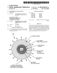
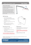
X340 Series LED Medical Examination Lights User Manual & Installation Guide QAM.X340.0915.5 Page 1 of 26 Table of Contents 1. Introduction ........................................................................... 3 1.1 Supported Lights ................................................................. 3 1.2 Lighting Specification ........................................................... 3 1.3 Pre-Installation Responsibilities and component packing list ........... 4 2. Operation .............................................................................. 5 2.1 Range of Motion .................................................................. 5 2.2 Pre-Start Checks ................................................................. 6 2.3 Powering On & Variable Intensity ............................................ 7 2.4 Operating the Downtube ....................................................... 8 2.5 Adjusting the Lighthead ........................................................ 9 3. Installation ........................................................................... 10 3.1 Considerations .................................................................. 10 3.2 Ceiling Mounted Lights......................................................... 11 3.2.1 Attachment methods and void suspension ............................ 11 3.3 Lighting configuration ......................................................... 12 3.3.1 Affixing the Ceiling plate ................................................ 12 3.3.2 Wiring and transformer layout .......................................... 13 3.3.3 Downtube adjustment and installation ............................... 14 3.3.4 Lighthead and arm fixing ................................................ 17 3.4 Wall Mounted Bracket Assembly ............................................. 18 3.4.1 Considerations ............................................................. 18 3.4.2 Placement and Installation .............................................. 19 4. Maintenance ......................................................................... 20 4.1 Maintenance schedule ......................................................... 20 4.2 Safety Precautions.............................................................. 20 4.3 Cleaning .......................................................................... 21 4.4 Fuses and their replacement ................................................. 21 4.5 Adjustments ..................................................................... 22 4.5.1 Rigid Arm Adjustments ................................................... 22 4.5.2 Detaching Parts ............................................................ 22 5. Troubleshooting Guide ............................................................. 23 6. Replacement Parts .................................................................. 24 7. Warranty Information .............................................................. 25 7.1 Returns Policy ................................................................... 25 7.2 Warranty Details ................................................................ 26 Page 2 of 26 1. Introduction Thank you for choosing a Daray X340 examination light. The X340 Series of lights are specifically designed to meet the demanding needs of today’s medical department whilst providing the finest quality design with superior performance, reliability and value. The X340 examination light has a smooth, spring balanced arm and a telescopic ceiling tube making the light extremely versatile, perfect for gynaecological procedures. This user & installation guide contains all the information you need for installation, operation and maintenance. For further information on our product range and find out more about our company please visit www.daray.co.uk or call 0333 321 0971 This product was designed & manufactured in Great Britain by: Daray Ltd. Marquis Drive, Moira Swadlincote Derbyshire DE12 6EJ 1.1 Supported Lights The Following Models are supported in this Manual X340 Examination Light X340LC Ceiling Mount X340LW Wall Mount 1.2 Lighting Specification Light Specifications Light intensity @ 0.5m 50,000 lux Light intensity @ 1m 12,500 lux Colour temperature 4,300K Colour Rendering Index Ra = 95 Red Rendering R9 = 88 Reach 1000mm Voltage 30V 1A 12W Base of arm rotation 300° Head rotation 320° Body Colour RAL 9016 white 1000mm supplied as standard Downtube (2000mm optional) Page 3 of 26 1.3 Pre-Installation Responsibilities and component packing list This document is a guide to the steps that need to be performed to correctly install the X340 Examination light. However, the work required to be performed is the responsibility of the owner or designated contractor/s. All fixings between Daray lights and the building super-structure must be approved by either the chief project engineer or an appropriate and competent structural assessor. The components supplied by Daray for fitting / installation should be the following items in the specified quantities. X340 Ceiling Mounted 1m or 2m Downtube with internal arm Ceiling Mount Plate Optional (Ceiling Mount Cover) Suspended Ceiling Cover Qty. 1 1 1 1 Microfibre cloth Light head and spring balanced rigid arm User Manual Warranty Card (found in back of User Manual) 1 1 X340 Wall Mounted Plug top transformer Wall bracket Thumb Screw for Wall Mount Light head and spring balanced rigid arm Microfibre cloth User Manual 1 1 Warranty Card (found in back of User Manual) Qty. 1 1 1 1 1 1 To use the ceiling mounted edition of the X340 the fixing point for the light must be between 2.4m – 3.9m from the floor; anything over 2.9m will require Daray’s 2m downtube to then be customised. Height of Ceiling Plate from Floor Length of Downtube Required 2.4m 2.65m 2.9m 3.4m 3.9m 500mm 750mm 1000mm 1500mm 2000mm Page 4 of 26 2. Operation 2.1 Range of Motion Ceiling Mount The full range of motion between the X340 series varies. This is an image depicting the range of motion on a standard ceiling mount fitting. Lighthead Retainer Ring Downtube Thumb Screw Rigid Arm Thumb Screw Downtube Extension Thumb Screw Page 5 of 26 2.2 Pre-Start Checks Please check that the power cable (when applicable) is without visible damage, harsh folds, knots or cuts in the rubberised coating Please make sure the light head itself is not directed at people’s eyes as the light will illuminate when powering on Check that the cable is fully connected to the device and if you are using a plug top power supply, check that the plug is fully inserted into the socket and then switch the power on Downtube DC Jacks Thumb Screw Page 6 of 26 2.3 Powering On & Variable Intensity The X340 Series uses a single button (on the back of the head) to power the light on and off. This switch also controls the lights variable intensity; hold the button in, to change the light intensity up or down. Please Note, The variable intensity control has a memory function; whereby, if the light is turned off at a dimmed level, it will remember that level the next time it is turned on. Push-button controller Thumb screw Page 7 of 26 2.4 Operating the Downtube The inner extension arm in the downtube extends to a maximum of 300mm. (See image.) This extension is controlled by a thumb screw located around the back of the primary downtube. 300mm Thumb Screw Loosening the thumb screw will allow you to reposition the light to the required height. Please ensure you use your free-hand to control the speed that the light lowers at, to make sure it doesn’t freely drop. Page 8 of 26 2.5 Adjusting the Lighthead The X340 head is secured using a large thumb screw. This also controls the forward and backward motion of the head itself. Thumb Screw Loosening this thumb screw will allow you to position the lighthead up or down. Care should be taken not to over tighten the screw. Page 9 of 26 3. Installation 3.1 Considerations The procedures below are detailed to a high level however If in doubt please consult a qualified electrician. Minimum Room Requirements Maximum Room Requirements The X340 ceiling mounted light has an internal extension that protrudes out from the main downtube, considerations for this and the amount of downtube required to fixing into the ceiling plate means that the minimum length of downtube is 500mm. Therefore the minimum allowed room height is 2.4m Please note, if the fixing point of the light is above 3.9m then a uni-strut platform and a 2m downtube will need to be constructed to bring the ceiling plate down to the required height. Live Electric Circuitry All personnel working around live circuitry should be qualified and following proper procedures Heavy or Difficult fittings Fitting the ceiling plate can be difficult and aspects of the fitting may require more than one person; this work should only be attempted by appropriate and competent personnel. Existing Environmental Factors When fitting, considerations have to be taken for existing services such as; fire alarms, vents, lights, etc. along with interior ceiling construction and any surrounding hazard. Environmental Responsibility Once our products are installed all packaging should be disposed of appropriately and recycled where appropriate and in accordance with local governing regulations. These instructions are based on the assumption of a fresh fit into a room with no previous lighting structures. With installations onto sites with equipment already in place, we recommend that the previous lights’ mounting plate be removed and the new one fitted as if into a fresh fitting. Page 10 of 26 3.2 Ceiling Mounted Lights After concluding the structural stability of the ceiling structure it will be necessary to assess the construct and decide on the best course of action for installing the ceiling plate. There are various different methods for loading the plate onto the ceiling, below are various example methods that can be used. 3.2.1 Attachment methods and void suspension Please note, the minimum room height allowed for fixing requires the bottom of the ceiling plate to be no lower than 2.4m. Bolted Directly into the structure and secured with chemical bonding The is our primary choice for mounting our lights to the ceiling structure, appropriate rawl bolts and chemical bonding should be used to secure the fitting. Bolted to a Uni-strut Construct When using a uni-strut construct for mounting the ceiling plate, you should ensure that the uni-strut is cross braced to ensure it is secure and does not move. Weight dispersed over several timber frames This can be used when fixing the light to a timber frame structure in a room with a suspended ceiling. We recommend sandwiching or affixing uni-strut to the timber with a span of at least 4 rafters / joists with the uni-strut and then fixing the ceiling plate to the strutting to disperse the weight. Page 11 of 26 3.3 Lighting configuration Dependant on the choice of attachment method, and whether the light is being attached in a void or directly onto an open surface ceiling; custom mounting aspects may be required. Daray’s standard mounting recommendation is to have the ceiling plate directly bolted into the structure when possible. This would also be suitable for non-voided areas with use of a Daray standard ceiling mount cover. Ultimately the mounting method used is the responsibility of the project engineer or fitter. This includes the specification of attachment hardware, lateral bracing and the suitability of the surface to be fixed to. 3.3.1 Affixing the Ceiling plate The location of the light should be decided by the end user / project manager or through schematical drawings. Once the location has been decided it will be necessary to first mark the location of the securing points. This is done by placing the ceiling plate on the roof and using the holes in the plate as a template, mark the locations of the securing points on the fixing structure. Securing Points Remove the plate, now drill holes relevant to the structure and securing bolts used. Please use appropriate fixings when securing the plate to the ceiling. Once the plate has been fitted, it will be necessary to ensure that it is balanced on the horizontal plane. This can be achieved by adjusting the three large bolts. After any adjustment it will be necessary to check that all fixings are still sound and that locking nuts are tight. Page 12 of 26 3.3.2 Wiring and transformer layout Before working on electrical connections please make sure that the power to the light is switched off at the source and secured so that it will not be turned on during your work. Ideally the cable used to power the light should be of a 1.5mm twin and earth type. Daray recommends that the power supplied uses an earthed switched fused spur, protected with a 3amp fuse. The wiring should be as follows: Live terminal brown wire. Neutral terminal blue wire. Earth terminal green/yellow wire. The above wiring is for modern wiring applications (post 2000). On completion of the wiring, the next process is to determine the length of the downtube. Take the cable from the downtube and attach the wires to the choc block in the following layout. Cable from the top of the downtube should be inserted here Pre-installed Transformer is fitted here and should not require any work Mains Power should be inserted here Fuse Holder – 1 Amp Fuse - CS6144 The cabling leading to the transformer is black and should already be attached. To connect the cabling from the transformer into the main power we recommend you use an earthed switched fused spur. Page 13 of 26 3.3.3 Downtube adjustment and installation The downtube provided will be either 1m as standard or 2m (optional) maximum. It is Daray`s recommendation that the bottom of the downtube is approximately 1900mm from the floor, therefore the minimum room height suitable for the ceiling mounted light is 2.4m. Below is a quick table showing situational examples of what length downtube would be required Height of Ceiling Plate from Floor 2.4m 2.65m 2.9m 3.4m 3.9m Length of Downtube Required 500 750 1000 1500 2000 With the X340 Series the minimum length the downtube can be cut to is 500mm; this is due to the space required for the internal second arm and the space required to attach the downtube to the ceiling plate. When cutting the downtube to length it is highly recommended that you pull the wire back through the downtube so that you don’t cut through it. This can be achieved by extending the secondary internal arm and pulling the wire down through the hole in the bottom. Pull the cable out in this direction Page 14 of 26 Once the downtube has been cut to length it will be necessary to de-burr the end of the pipe, we also recommend doing this to the inner and outer edges of the safety bolt’s drill hole as this will prevent damage to the cable. Before drilling the safety bolts hole, please direct spigot on the bottom the downtube toward the centre of the examination area to allow the best range of motion over the examination area. Direct this part of the downtube toward the centre of the examination area With the downtube directed it should be loosely fitted between the two metal clasps and then holes should be marked on the tube for where the safety bolt will go through; then remove the downtube and secure for drilling. A 7mm hole should be drilled through the downtube on both sides to allow the bolt to pass through. Mark the location of this hole and drill Page 15 of 26 Now you should put the rubber retainer ring onto the downtube followed by either the ceiling trim or ceiling mount cover. This is to allow the covers to be fixed into position after you have attached the downtube to the ceiling plate. Ceiling Mount Cover Suspended Ceiling Mount Cover Rubber Retainer Ring Thread the wire back through the downtube and the hole in the middle of the ceiling plate; then place the downtube between the clasps on the ceiling plate. Slide the safety bolt through the clasps and the downtube (being careful not to catch the wire). Be sure to tighten the safety bolt and the nylon locknut. Feed Cable Through It will be necessary to ensure that the downtube is absolutely vertical. To prevent arm drift. This can be achieved by adjusting the three bolts on the plate, then use the locking nut on the bolts to lock the adjustment. After any adjustment it will be necessary to check that all fixings are still sound and that locking nuts are tight. Adjusting Bolt Locking Nut Now push the ceiling cover up onto the mounting bracket and roll up the rubber retaining ring to stop the cover from dropping back down. Page 16 of 26 3.3.4 Lighthead and arm fixing Lubricate the Spigot and insert arm into downtube and tighten the thumb screw. Care should be taken not to over tighten the screw. Now simply attach the cables using the DC jacks coming out of the arm and the downtube together. Lubricate Thumb Screw Connect the DC Jacks The light can now be tested by applying power and pressing the power button on the back of the head. Check the arm and head for smooth and correct movement. Your new Daray light is now ready for use. To gain full support of our warranty please fill in our warranty web form or contact Daray by phone or email. Daray also provide service plans to help you maintain your light. Contact Daray on 0800 878 9864 for more details. Page 17 of 26 3.4 Wall Mounted Bracket Assembly The wall bracket needs to be true on the vertical plane. 3.4.1 Considerations Wall Construction Before fixing it is important to consider the strength of the wall and the depth of the fixings used. Use of a building engineer or structural drawings may be required to decide on suitability. Examinations to be undertaken The Wall mounted version of the X340 lacks the 300mm downtube extension of the ceiling mounted edition. Therefore we recommend the bracket be installed approximately 1300mm from the floor to the top of the bracket. It may be necessary to adjust this height, if there are specific medical procedures the light will be used for. If in doubt consult the end user or DARAY. When installing the bracket take consideration of where you want the lighthead to sit when in its lowest position. Locations of nearest mains sockets The X340 wall mounted light uses a plug top transformer with a DC jack connection. Only the supplied certified power adapter should be used with the light. The length of this cable is approximately 1.5m so the wall mounted light should be within 1.2m of a mains power point Page 18 of 26 3.4.2 Placement and Installation The power supply for the X340 series is a plug top transformer with a DC jack connection, these can be inserted into any standard UK wall socket. Please note, under no circumstances should this product be connected directly to the Mains electrical supply, this product requires a Low Voltage Connection only and must only be used with a Daray Certified Power Adapter. The light can now be tested by connecting the DC jacks, applying power and pressing the rocker switch on the head. Check arm and head for smooth and correct movement. Your new Daray light is now ready for use. To gain full support of our warranty please fill in our warranty web form or contact Daray by phone or email. Daray also provide service plans to help you maintain your light. Contact Daray on 0800 878 9864 for more details. Page 19 of 26 4. Maintenance The proposed maintenance is only a suggestion. Depending on the use of the product and the operating environment, this may need to be revised more often. Daray would strongly recommend against “quick fixes” with tape, etc. If you cannot resolve a problem then please contact our helpline on 0800 878 9864 or email [email protected] 4.1 Maintenance schedule Weekly checks should include:- Range of movement testing, it should be light and easy to move throughout the range No visible signs of excessive wear. Monthly checks to include:Six monthly checks to include:- Check the downtube and thumb screws for wear and report as necessary Remove head and clean the interior of the hinge Remove arm, clean spigot and re-grease as necessary. Check all electrical connections are sound and that there is no visible cable wear. All fixings to be checked and be of sound construction. 4.2 Safety Precautions For all cleaning work, power off the equipment and where possible unplug the mains socket, only minimal cleaning fluids should be used. Please do not look directly into the light source when illuminated. If the equipment is dented or scratched this should not impact the usability of our lights however we advise that if the BioProtect® coating is damaged and the metal casing underneath is visible, please do not attempt to ‘paint’ over it as this will impact upon the effectiveness of the coating, simply use an alcohol based cleaning spray when cleaning and pay special attention to the cut. If there is damage to the power cable or if exposed wire is visible DO NOT USE Page 20 of 26 4.3 Cleaning Do not use strong chemical cleaning agents or any abrasive materials to clean the light. The light is not waterproof so the use of excessive amounts of cleaning fluids could cause serious harm or injury. The X340 Series lights are BioProtected on all painted surfaces and have fully enclosed heads with an Ingress Protection (IP) rating of 54. We advise that the light should only be dusted with a soft flannel cloth, and the front cover gently cleaned with an alcohol-based liquid (aerosol) spray, and wiped dry. 4.4 Fuses and their replacement For the ceiling mounted light the fuse is located on the ceiling plate on the terminal block connector (as shown in section 3.3.2). The fuse tray can easily be removed by hand and the fuse replaced. The fuse supplied is 1 amp and this can be ordered from daray using the code CS6144. Replace the fuse and check that light is fully functional. If fuse blows again then it may need investigating further by an engineer. Page 21 of 26 4.5 Adjustments The head of the X340 series light has a 180 degree forward and backward motion; this is adjusted secured by the thumb screw at the bottom of the lighthead. The head has a total turning capability of 320 degrees, attempting to push further may cause damage to the movement and internal wiring of the light. 4.5.1 Rigid Arm Adjustments The X340 Series are all mounted on spring tensioned rigid arms which are balanced specifically to be able to be moved using a single finger touch. Warning! These arms are under spring tension, as such do not try and adjust the internal mechanics of the arms. These arms shouldn’t need adjustment in their life cycle however if they start to droop or require any other work, we recommend that you contact Daray customer services to discuss this. 4.5.2 Detaching Parts De-construction of the lights should be done following a reverse order of the instructions in section 3. The X340 is a completely enclosed light and arm it should not be opened and is not serviceable outside of a Daray Authorised service centre. For any issues requiring service work on the X340 please contact daray, as unauthorised work will invalidate the warranty. Page 22 of 26 5. Troubleshooting Guide Problem Possible Cause Power Supply No light output On/Off/Intensity Button Fuses Cables Power Button Please check the variable intensity is not just set to its minimum. To do this hold in the power button on the back of the head. This is the control used to adjust the intensity. If the light reduces more, simply remove your hand and then depress the button again Voltage in Verify that the correct mains voltage and correct transformer is being used Verify correct secondary voltage (approx. 30V nominal under load) In the unlikely event that this happens, please contact Daray On installation the arm has most likely not been vertically aligned and levelled. Please contact the original fitter or a qualified electrician Please check the tightness of the thumb screw adjuster just below the head of the light Poor Light output Voltage out Light patch not focused Arm drift sideways Head movement or drift Corrective Actions Wall Version - Check the plug top adapter is plugged in and switched on at the power socket. Ceiling Version - Check that the switch for the power supply is switched on Press the button on the back of the light to check if the light will power on (if dimmed refer to poor light output actions). Visually check fuses then check continuity with meter Check the visible wiring and make sure the DC connectors between the light and the downtube / PSU are fully connected Light head Wall mount or downtube Light head Page 23 of 26 6. Replacement Parts Picture Description Order Code Lighthead handle CS6142 Head thumb Screw CS6143 Wall bracket and downtube extension thumb screw CS6141 Plug-top transformer CS6148 1 Amp ceiling plate fuse CS6144 Page 24 of 26 5 7. Warranty Information 7.1 Returns Policy IMPORTANT! Please fill out your warranty registration online at www.daray.co.uk/warranty or contact Daray by phone (0800 878 9864) or email [email protected] DARAY's standard warranty is 12 months. However, this period may be extended for most lighting products from 3 to 5 years* free of charge by completing and submitting the warranty registration. Year 1: Year 2-5: Warranty includes parts and labour (Return to Base) Parts only *UK only We want you to be completely satisfied with your purchase. If you need to return goods purchased from DARAY Ltd, please read the following information carefully. The DARAY Ltd returns policy provides guidance on when you can return goods we have supplied, and what you can expect from us once you do. To see our detailed returns policy and procedure visit www.daray.co.uk/returns TYPE OF RETURN REMEDY DAMAGED GOODS We must be notified within 24 hours of receipt. Goods which are physically damaged on delivery Dead On Arrival (DOA) Goods which do not work Goods which do not work on arrival or develop a fault within 28 days, we will advance replace the item. GOODS DEVELOPING A FAULT Goods which have developed a fault within the warranty period. If the fault develops after 28 days, but within the warranty period, we will initiate the returns procedure. NON WARRANTY If a fault develops outside the warranty period, we will Goods which have developed a fault outside the initiate the returns procedure charges may be applicable. warranty period. OTHER We will always try to help, but we cannot normally offer a Any situation which is not covered by any of the refund. above. For additional clarification, please refer to our terms and conditions at www.daray.co.uk/terms. In a small number of cases, we may determine that a replacement would not work any better than the original product we supplied. In such cases we will only offer a refund rather than a replacement for qualifying returns. Replacement bulbs and spare parts ordered on our website or from supplied part codes are not eligible for credit. We will accept returns and exchange for the correct item. If your purchase an item incorrectly you can return it within 14 days and it can be exchanged for another product of equal or higher value, excluding transportation charges incurred. Goods and packaging must be returned in their original condition. Under no circumstances will goods be accepted for return if they are damaged, have been subjected to improper handling or abuse or have been used. If you send us goods that do not qualify for return, you will invalidate your claim to any refund, and you will be obliged to compensate DARAY Ltd for the cost of return postage and any other reasonable costs incurred processing the goods. Your statutory rights are not affected. Page 25 of 26 7.2 Warranty Details TERMS AND CONDITIONS OF WARRANTY 1. To qualify for this warranty you must register on www.daray.co.uk or return to Daray Ltd (Daray) the duly completed warranty-registration form accompanying the product. 2. Daray warrants this product (excluding lamp) against faulty material and workmanship during the period of the warranty. The period of warranty is the period stated on your warranty card and commences on the date of purchase of the product. In the event that the product is not in good working order Daray will provide, during the warranty period, a free repair service within the United Kingdom. The warranty is subject to proof of purchase being provided; therefore, you should retain your original receipt. 2.1 The repair service consists of the provision of spare parts and/or replacement products (at Daray’s discretion) which will be provided on an exchange basis and will either be new, equivalent to new or reconditioned. All replaced spare parts and products shall become the property of Daray. 2.2 Daray’s only obligation under this warranty is the provision of the service as set out above. 2.3 All products are returned to Daray at the customer’s cost and risk. Products to be returned should be adequately packed. For the address to send returns to please visit www.daray.co.uk 3. Daray’s arrangements for providing service provided under this warranty may include the use of subcontractors. 4. This warranty does not cover damage or defects in the Product caused by or resulting from: Wilful neglect or negligence by anyone other than Daray; Improper use, storage or handling of the product; Use of non-Daray approved parts (such as replacement lamps) not compatible with the Product; Fire, accident or disaster; Use of non-Daray modifications other than in accordance with Daray’s instructions; Attachment of fittings and accessories not approved by Daray; Repairs, modifications carried out by service personnel not approved by Daray; Damage caused by chemical corrosion from cleaning agents not approved by Daray. Failure to use or install the product in accordance with the manufacturer’s instructions. 5. Nothing in this warranty shall have the effect of restricting or excluding the liability of Daray in respect of: a) Death and personal injury caused by the negligence of Daray, or for fraud; b) Under the Consumer Protection Act 1987 to a person who has suffered damage caused by a defective product or to a dependant or relative of such a person; c) Direct damage to your property caused by the proven negligence of Daray. 6. This agreement does not give any rights other than those expressly set out above and in particular, Daray will not be responsible for any loss of income, profits or contracts or any direct or indirect consequential loss, damage caused to or suffered by the purchaser as a direct result of this agreement. 7. This warranty is offered (subject to these terms and conditions) in addition to, and does not affect your statutory rights. 8. Daray may disclose your details and other personal information to companies within the Daray group including any subsidiary company or sub-contractor of Daray for the purposes of performing our obligations hereunder. 9. You must not resell outside the UK any products supplied by Daray and covered by the Export of Goods (Control) Order 1992 (or any law that replaces it) without obtaining all necessary licences. You also agree not to sell the product in the UK if you know or think that the person buying the product intends to export it without getting the necessary licences. You agree to impose similar conditions to these on anyone you sell the product to. 10. These conditions shall in all respect be governed and construed in accordance with English law and the exclusive jurisdiction of the English courts. Product: Serial No: Page 26 of 26