1
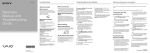
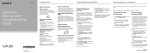
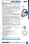
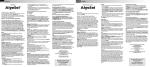
Usage and maintenance manual
for the fall arrester system of
the Söll GlideLoc® type with a guided type fall arrester
“Söll Comfort”
Order No. 22697 with self-locking karabiner hooks
Order No. 22690 with bolted karabiner hooks
in accordance with EN 353-1:2002 / CNB/P/11.073
and CSA Z259.2.1-98
Serial number:
Date of purchase:
(The initial test is done by the manufacturer before shipment.
The yearly inspections have to be documented in the inspection logbook.)
The user must fill in the following details using an indelible pen:
Date of commissioning:
Operating company/user:
Street:
Location:
Tel.:
Fax:
Safety At Height Limited
Unit 1 Pennine View, Marple, Stockport
Cheshire, SK67JW
Tel: +44(0)161 446 5615
1
www.safety-height.co.uk
Contents
Page
A
General information
3
B
Inspection before climbing
4
C
Using the fall arrester
5
D
Removing the fall arrester
9
E
Maintenance
9
F
Care
14
G
Storage
14
H
Inspection logbook
15
This manual is protected by copyright.
Duplicating and circulating this manual is not permitted
without written consent of the author as per §§16, 17 German Copyright Act (UrhG), and Honeywell Fall Protection
Deutschland GmbH & Co. KG reserves the right to prosecute as per § 106 German Copyright Act (UrhG) in case of
any violation.
Changes in this edition: Page 1: Definition „initial test, yearly inspection“
Safety At Height Limited
Unit 1 Pennine View, Marple, Stockport
Cheshire, SK67JW
Tel: +44(0)161 446 5615
2
www.safety-height.co.uk
A General information
Note:
EN standards references apply to users of the product in the European Union.
CSA standards references apply to users in Canada. CSA certification is applicable to the fall arrester and rail system only.
A 1. Read this manual and understand its contents before usage. Actions contravening this manual may put people’s lives at risk.
Note:
The Söll Comfort fall arrester may not be used in explosion-prone areas.
A 2. For the users’ safety, it is important that the retailer provides this manual in
respective country’s language if this system is re-sold in another country.
A 3. The maximum user load (including the clothing and equipment) may not exceed
140 kg.
Operating temperature for the fall protection system:
-40 °C to +70 °C
A 4. A safety distance of 3.0 m between the users must not be undershot.
A 5. The “regulations for using personal protective equipment against falls from a
height”, i.e. BGR 198, of the Institute for statutory accident insurance and prevention as well as the rules for using personal protective equipment for holding
and rescuing, i.e. BGR 199, must be observed.
A 6. The “Söll-Comfort” fall arrester is component of the Söll fall protection system
with a fixed guide of the Söll GlideLoc® type compliant with EN 353/Part 1
and has been designed for use as personal protective equipment only for the
intended use of the Söll fall protection system. The operating company of the
fall arrester system must suitably ensure that the full body harness and the fall
arrester belong to the user and that they are used according to the instructions.
After use, the fall arrester must not be left inside the fall protection system.
The Söll Comfort fall arrester must be operated only in the original Söll
fall arrester systems that have the Söll GlideLoc® type EG-test certificate.
Using systems of other manufacturers may hamper the functioning of the fall
arrester.
In such cases Honeywell Fall Protection Deutschland GmbH & Co. KG and its
authorised dealers refuse product liability. The operating company shall then
be completely responsible.
Safety At Height Limited
Unit 1 Pennine View, Marple, Stockport
Cheshire, SK67JW
Tel: +44(0)161 446 5615
3
www.safety-height.co.uk
A 7. Full body harnesses must be approved in accordance with EN 361 or CSA
Z259.10 (class AL). Only certified arrester elements (marking with “A”) may
be used.
Note:
The fall arrester Comfort must always be connected with the certified arrester element of the harness.
A 8. The fall arrester should always be handled in a manner that will protect it
from damage or corrosion.
A 9. Relevant notified body: DEKRA EXAM GmbH, Dinnendahlstr. 9,
44809 Bochum, CE 0158.
A10. The maximum arrest distance, when dynamically tested in accordance with
the requirements of the CSA Z259.2.2-98 standard, amounts to 1m.
A11. Use of the fall arrester is not suitable when the user is positioned on an unstable surface, fine grain material or particulate.
B Inspection before climbing
B 1. Before using the guide, the fall arrester, intermediate joint and karabiner
hooks, always check their usage capability and correct functioning. (See the
Maintenance check list for this purpose).
B 2. Do not use the fall arrester system if there are apparent defects or doubts
regarding the safety of the system. Do not use it until an expert approves
it for further use. Send the system components back to the manufacturer if
required.
B 3. Before and while climbing, ensure safe and effective implementation of rescue measures.
B 4. The user must be in good health and must not be under the influence of alcohol, drugs or medicines.
B 5. Note:
Utmost care must be taken when ascending and descending in the first 2
m of the ascent route since it may not be possible to prevent the user from
hitting the ground in some cases.
B 6. Warning:
The specific influence of the arresting mechanism when ascending and descending may hamper the safe functioning of the fall arrester.
Safety At Height Limited
Unit 1 Pennine View, Marple, Stockport
Cheshire, SK67JW
Tel: +44(0)161 446 5615
4
www.safety-height.co.uk
C Using the fall arrester
Figure 1
Warning
C 1. The fall arrester system and the full body harness secure the users against
falling when ascending or descending. When working in or next to the ascent
route and when executing tasks and actions that are not a part of the usual
ascent and descent movements, the climber must additionally secure himself/
herself with a lanyard in accordance with EN 354 (or CSA approved) or a
lanyard for the working positioning belts in accordance with EN 358 (or CSA
approved). (Safety using an anchor device) This is also applicable for positions that are intended to take a break on the ladder. Only suitable anchor
devices such as a mounting bracket must be used for this. In all these situations, the lanyard must be held tight in order to prevent a fall (see figure 1).
Figure 1
EN 354/355
EN 358
An EN 353-1 compliant fall arrester system should be used only by those persons who
• are trained and/or are otherwise competent or
• are directly supervised by a trained and/or a competent person.
Safety At Height Limited
Unit 1 Pennine View, Marple, Stockport
Cheshire, SK67JW
Tel: +44(0)161 446 5615
5
www.safety-height.co.uk
Figure 2
C 2. Push the fall arrester into the lower end of the anchorage rail (6.0) or in the
recess (6.1) (that must always be provided at the stomach height or deeper)
(see view “A”). The laterally protruding locking pin (1.2) must be on the right
side and the engraved arrow (1.10) on the side of the fall arrester must point
upwards.
The locking pin (1.2) and the end stop (7.0) prevent the incorrect use of
the fall arrester and unintended slipping from the anchorage rail.
Figure 2 - illustration: self-locking karabiner hooks
View “A”
Warning:
Crossing the end stop is allowed only
• in the areas without the risk of a fall from heights or
• if the safety against falls from heights is ensured using other means.
Safety At Height Limited
Unit 1 Pennine View, Marple, Stockport
Cheshire, SK67JW
Tel: +44(0)161 446 5615
6
www.safety-height.co.uk
Figure 3
C 3. Open the karabiner hook (4.0/5.0) on the fall arrester.
a) In case of the self-locking karabiner hook, turn back the knurled bushing (4.1) and push it inwards.
b) In case of the bolted karabiner hook, turn back the knurled bushing (5.1/
Figure 6) entirely and push it inwards.
Attach it directly to the front arrester element of the full body harness.
a) In case of the self-locking karabiner hook, the knurled bushing (4.1)
must lock automatically once it is released.
b) In case of bolted karabiner hook, tighten the knurled bushing (5.1 /
Figure 6) again.
Attention!
An unsecured karabiner hook (open knurled bushing) is dangerous to human
life.
Figure 3 - illustration: self-locking karabiner hooks
front D-ring of
harness
harness
Correct
body
Safety At Height Limited
Unit 1 Pennine View, Marple, Stockport
Cheshire, SK67JW
Tel: +44(0)161 446 5615
Incorrect
7
www.safety-height.co.uk
Figure 4
Warning: Risk to life!
The karabiner hook of the fall arrester must be directly inserted into the
front arrester element (marking with “A”) of the full body harness for the
vertical and horizontal usage in compliance with EN 353/1. CSA requires
that the device is connected directly to the front arrest element of a class AL
harness. The length between the outer edge of the anchorage rail and the
internally bent eyelet on the harness, as required by both EN and CSA standards, may not exceed 200 mm (see Figure 3).
Figure 4
Front arrester element
Attachment
element
Attachment
element
C 4. The stomach or chest harness of the full body harness must fit firmly
on the body (see Figure 3)
C 5. The ladder can now be used. When descending, the latch (Figure 6 / Detail
2.0) of the fall arrester must be unlocked. Two options are available for this:
a) The user can lean backwards and unlock the latch
b) If the user goes near the ladder, the fall arrester suspends downwards.
The latch is unlocked due to the weight of the fall arrester.
Safety At Height Limited
Unit 1 Pennine View, Marple, Stockport
Cheshire, SK67JW
8
Tel: +44(0)161 446 5615
8
www.safety-height.co.uk
D Removing the fall arrester from the
anchorage rail
Warning:
Protection against falls from heights must be ensured using a different method before removing the fall arrester from the anchorage rail.
D 1. To remove the fall arrester from the anchorage rail, the corresponding end
stop (Figure 2 / detail 7.0) must be crossed. For this, fold the locking latch
(Figure 2 / detail 7.1) of the end stop upwards/downwards.
When using an exiting device, observe its valid operating manual.
E Maintenance
E 1. A fall arrester system damaged due to a fall must be used again only after
testing by an expert. The fall arrester and the manual must be sent to the
manufacturer’s workshop for checking and maintenance.
E 2. Depending on the application and operating conditions, an expert must check
the fall arrester system for its flawless condition as required, however at least
once a year.
An expert for the personal protective equipment is:
A person who can has a certificate for successfully participating in a course
compliant with the "fundamental principles for selecting and training the experts in the field of personal protective equipment against falls from a height
and certifying their qualification", i.e. BGG 906.
Safety At Height Limited
Unit 1 Pennine View, Marple, Stockport
Cheshire, SK67JW
Tel: +44(0)161 446 5615
9
www.safety-height.co.uk
E 3. Expert test (also see Figure 6 for this)
Use the “maintenance check list” for the expert test.
An expert can rectify the following defects:
• Removing dirt (concrete, mortar, colour, etc.) on the body and running surfaces
• Cleaning the labels
• Replacing the stickers
In case of dirt inside the shuttle and defects that necessitate partial dismantling of components, the shuttle must be sent to the manufacturer’s workshop
with suitable notification (and with the manual) to rectify the defects. This
process must be recorded in the annexe of the check list (space for comments).
Owing to safety reasons, repairs may be carried out only the
manufacturer’s workshop.
Figure 5
Example of marking:
Figure 5
Year of manufacture
- X 00
Serial number
- 0000
- monitoring testing agency
- Note for reading the operating manual
Söll GlideLoc
- type designation of the fall arrester system
EN 353-1:2002
- reference to the European standard
CNB/P/11.073
- reference to additional test regulations
Z259.2.1 Class FRL
- reference to the Canadian standard
min. 40 kg max. 140 kg
- minimum/maximum weight of the user
- approval mark for Canada
Once the expert ensures that the maintenance is fault-free, he/she can affix a
test label on the fall arrester.
Safety At Height Limited
Unit 1 Pennine View, Marple, Stockport
Cheshire, SK67JW
Tel: +44(0)161 446 5615
10
www.safety-height.co.uk
Maintenance check list (see Figure 6 for this)
Body (1.0)
•
•
•
•
•
•
•
•
•
Free from colour/mortar/concrete/dirt, etc.
The marking (1.9) on the lower side must be clearly legible
The locking pin (1.2) fits firmly and is not bent (check by turning it)
Running surfaces (1.1) must be clean
Sliding pieces (1.4) must be available *
Sliding pieces (1.4) must not be worn out *
Rubber belt (1.6) is available and not damaged *
Stickers (1.7/1.8) are available and not damaged *
Engraved arrow (1.10) can be easily identified
Latch (2.0)
•
•
•
It must move freely
It must not be deformed (2.2), maximum 58 mm
Interception catch length (2.1) 14.0 mm +1.0/-0.5 mm
Running rollers (1.3), total 10 units
•
•
•
•
•
Axial clearance: maximum 0.5 mm
They must rotate freely (concentricity)
They must not be damaged
They must fit firmly on the axle
The minimum diameter of running rollers (1.3) must be 9 mm
Compression springs (1.5)
•
•
•
•
They must be free from rust
They must be free from dirt, concrete, colour, etc.
They must not be broken
They must not slip
* not relevant for safety
Safety At Height Limited
Unit 1 Pennine View, Marple, Stockport
Cheshire, SK67JW
Tel: +44(0)161 446 5615
11
www.safety-height.co.uk
Rotary shackle (3.0)
•
•
•
•
•
•
It can be moved
It must not be broken
It must not have cracks
The thickness of the rotary shackle (3.0) must be at least 5.5 mm
The shackle axle (3.1) is riveted
The maximum outer dimension of shackle pin eyelets (3.2) must be 40 mm
Karabiner hook (4.0/5.0)
•
•
•
•
•
•
•
•
•
It must not be bent
It must not have cracks
It must not be broken
The knurled bushing (4.1/5.1) must not be damaged
It must be possible to open the knurled bushing (4.1) easily
The knurled bushing (4.1) must close and lock automatically after opening and
releasing
It must be possible to open and close the knurled bushing (5.1) easily (open
and close)
The special nut (5.2) must not be damaged
The locking pin (4.3/5.3) must be available
Space for comments:
_________________________________________________________________
_________________________________________________________________
_________________________________________________________________
_________________________________________________________________
_________________________________________________________________
_________________________________________________________________
Safety At Height Limited
Unit 1 Pennine View, Marple, Stockport
Cheshire, SK67JW
Tel: +44(0)161 446 5615
12
www.safety-height.co.uk
Figure 6
Safety At Height Limited
Unit 1 Pennine View, Marple, Stockport
Cheshire, SK67JW
Tel: +44(0)161 446 5615
13
www.safety-height.co.uk
F Care
F 1. Wash the entire fall arrester with water and dry it using a suction cloth. Do not
use heat sources for drying.
DO NOT wash it with a quick cleaner, thinner or degreaser containing trichloroethane. Do not use grease.
F 2. Running rollers (Figure 6 / detail 1.3) have plain bearings and have been
lubricated in the factory.
F 3. Lubricate the rotary shackle (Figure 6 / detail 3.0) slightly.
F 4. Lubricate the knurled bushing (Figure 6 / detail 4.1/5.1) if required.
F 5. Attention! Do not bring the fall arrester in contact with chemicals.
G Storage
The fall arrester should be kept clean and as dry and dust-free as possible,
and should not be stored near heat sources.
When transporting ensure that the fall arrester is protected from damage.
Safety At Height Limited
Unit 1 Pennine View, Marple, Stockport
Cheshire, SK67JW
Tel: +44(0)161 446 5615
14
www.safety-height.co.uk
H
Inspection logbook
Date
Reason for working on the
Damage determined, repairs carried Name/signature of
system (regular inspection
out and other important details
the expert
or repair)
Safety At Height Limited
Unit 1 Pennine View, Marple, Stockport
Cheshire, SK67JW
Tel: +44(0)161 446 5615
Date of the
next regular
inspection
15
www.safety-height.co.uk