1
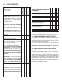
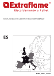
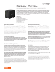
THERMO PRODUCTS USER MANUAL UK FI NO EE RU SE LV DK LP IE NL BY UK PL BE DE UA LU CZ SK FR MD AT CH HU SI RO HR BA YU BG PT IT ES MK AD AL GR Manuale Utente Termoprodotti - Rev004_280411 - Scheda 2272575 ENGLISH ............................................................... 5 1. WARNINGS ..............................................................5 2. SAFETY .....................................................................5 3. SAFETY DEVICES....................................................6 3.1. INSTALLATION AND SAFETY DEVICES ..................................6 3.2. SAFETY DEVICES FOR CLOSED VESSEL SYSTEM .............6 3.3. DISTANCES OF SAFETY DEVICES ACCORDING TO THE STANDARD ........................................................................................................7 4. HYDRAULIC SYSTEM .............................................7 4.1. TYPE OF SYSTEM................................................................................7 4.2. CLOSED VESSEL SYSTEM FOR AUTOMATIC LOADING APPLIANCES ........................................................................................................ 7 4.3. GENERALITY .........................................................................................7 4.4. SAFETY VALVES...................................................................................7 4.5. CLOSED EXPANSION VESSEL ......................................................8 4.6. COMMISSIONING CHECKS...........................................................8 5. AUTOMATIC THERMOSTATIC MIXER VALVE (MANDATORY) ..............................................................8 5.1. HYDRAULIC PLANT BASIC LAYOUT ........................................8 6. INSTANT DOMESTIC HOT WATER PRODUCTION ACCESSORY KIT .................................8 7. STOVE POSITIONING ............................................9 8. INSTALLATION........................................................9 8.1. INSTALLATIONS ALLOWED ..........................................................9 8.2. INSTALLATIONS NOT ALLOWED...............................................9 8.3. CONNECTION TO THE SMOKE EVACUATION SYSTEM .... 10 8.3.1. SMOKE CHANNEL OR FITTINGS ............................10 8.3.2. CHIMNEY OR INDIVIDUAL FLUE ............................10 8.3.3. CHIMNEY CAP..................................................................12 8.4. CONNECTION TO EXTERNAL AIR INLETS .........................12 8.5. INSULATION, FINISHINGS, COVERING AND SAFETY RECOMMENDATIONS ..............................................................................13 8.6. NATIONAL, REGIONAL, PROVINCIAL AND TOWN COUNCIL REGULATIONS ........................................................................13 ACTIVE...............................................................................................................22 13.2. ADDITIONAL THERMOSTAT FUNCTIONING WITH STBY DEACTIVATED ...............................................................................................22 13.3. ADDITIONAL THERMOSTAT INSTALLATION ...................22 14. THE REMOTE CONTROL ..................................... 22 14.1. REPLACING THE BATTERIES......................................................22 15. SETTINGS MENU ................................................. 23 15.1. SET CLOCK ..........................................................................................23 15.2. CHRONO ..............................................................................................24 15.2.1.RECOMMENDATIONS ..................................................24 15.2.2.PROGRAMMING EXAMPLE.......................................24 15.2.3.CHRONO MENU TABLE ..............................................25 15.3. LANGUAGE .........................................................................................26 15.4. USER .......................................................................................................26 15.4.1.SET THERMOSTAT ..........................................................26 15.4.2.ENABLE FAN ......................................................................26 15.4.3.DISPLAY ...............................................................................26 15.4.4.PELLETS ...............................................................................26 15.4.5.STAND - BY.........................................................................27 15.4.5.1. STBY WITH ADDITIONAL EXTERNAL THERMOSTAT ..........................................................27 15.4.5.2. HOW TO ACTIVATE OR DEACTIVATE STAND - BY ...............................................................27 15.4.6.KEYS LOCKED ...................................................................27 16. CLEANING UNDER USER'S RESPONSIBILITY 29 17. DISPLAYS .............................................................. 31 18. ALARMS ................................................................ 32 19. WARRANTY CONDITIONS ................................ 33 9. INSERTS INSTALLATION .................................... 13 9.1. 13 9.2. 9.3. 9.4. 9.5. 9.6. INSERT COMPARTMENT MINIMUM MEASUREMENTS ... AIR INLETS...........................................................................................14 AIR CIRCULATION PIPES .............................................................14 PREPARATION OF THE BASE AND AIR INTAKE ...............15 INSERT EXTRACTION ....................................................................17 ASSEMBLY ON COVERING ALREADY EXISTING ............17 10. PELLETS AND FEEDING ..................................... 19 11. PRODUCT FUNCTIONALITY ............................. 20 11.1. CONTROL BOARD...........................................................................20 11.2. DISPLAY ICONS KEY.......................................................................20 12. FUNCTIONING CYCLE ....................................... 21 12.1. BASIC INSTRUCTIONS ..................................................................21 12.2. IGNITION..............................................................................................21 12.3. WORK.....................................................................................................21 12.4. PUMP FUNCTIONING...................................................................21 12.5. SWITCH-OFF ......................................................................................21 13. ADDITIONAL THERMOSTAT ............................. 22 13.1. ADDITIONAL THERMOSTAT FUNCTIONING WITH STBY 3 4 1. WARNINGS Installation must be carried out by qualified staff and/or manufacturer technical assistance, who must provide the buyer with a declaration of conformity for the system and will assume full responsibility for final installation and as a consequence the correct functioning of the installed product. It is necessary to bear in mind all laws and national, regional, provincial and town council Standards present in the country the appliance has been installed. The manufacturer cannot be held responsible for the failure to comply with such precautions. 2. SAFETY For safety reasons, remember that: The stove must not be used by persons (including children) with reduced physical, sensorial and mental capacities or who are unskilled persons, unless they are supervised and trained regarding use of the appliance by a person responsible for their safety. Children must be controlled to ensure that they do not play with the appliance. Do not touch the stove when you are barefoot or when parts of the body are wet or humid. The safety and adjustment devices must not be modified without the authorisation or indications of the manufacturer. Do not pull, disconnect, twist electric cables leaving the stove, even if disconnected from the electric power supply mains. It is advised to position the power supply cable in a way that it does not come into contact with hot parts of the appliance. The power supply plug must be accessible after installation. WARNINGS 5 ENGLISH 1.Electric connections: it is therefore recommended that after any intervention on the product, that authorised staff pay particular attention to the electric connections, especially the stripped parts of the wires. These must not escape from the terminal board in any situation, thus preventing possible contact with the live parts of the wire. 2. Type of use: this stove must be destined for the use for which it has been expressly realised. 3.Liability of the manufacturer: The manufacturer is exempt from any liability, contractual and extracontractual, for injury/ damage caused to persons/animals and objects, due to installation, adjustment and maintenance errors and improper use. 4.Check integrity of the product: After the packaging has been removed, check the integrity and completeness of the contents. If this does not comply, contact the dealer where the appliance was purchased. 5.Electric connections: All electric components that make up the stove must be replaced with original spare parts exclusively by an authorised after-sales centre, thus guaranteeing correct functioning. 6.Maintenance:The stove must be serviced at least once a year, programming it in advance with qualified staff and/or the manufacturer's technical after-sales assistance. Nota bene: In case of thermo product or boiler, the product or system venting is not covered by the warranty. Do not close or reduce the dimensions of the airing vents in the place of installation. The airing vents are indispensable for correct combustion. Do not leave the packaging elements within reach of children or unassisted disabled persons. The hearth door must always be closed during normal functioning of the product. When the appliance is functioning and hot to the touch, especially all external surfaces, attention must be paid Check for the presence of any obstructions before switching the appliance on following a prolonged standstill period. The stove has been designed to function in any climatic condition (also critical). In particularly adverse conditions (strong wind, freezing) safety systems may intervene that switch the stove off. If this occurs, contact the technical after-sales service and always disable the safety system. If the flue should catch fire, be equipped with suitable systems for suffocating the flames or request help from the fire service. This appliance must not be used to burn waste Do not use any inflammable liquids for ignition During the filling phase do not allow the bag of pellets to come into contact with the product The majolicas are top quality artisan products and as such can have micro-dots, crackles and chromatic imperfections. These features highlight their valuable nature. Due to their different dilation coefficient, enamel and majolica produce crackling,. which demonstrate their effective authenticity. To clean the majolicas, it is recommended to use a soft, dry cloth. If a detergent or liquid is used, the latter could penetrate inside the crackles, highlighting the same. SAFETY DEVICES SAFETY DEVICES Key: * = present, - = not present COMFORT IDRO DUCHESSA IDRO ECOLOGICA IDRO MELINDA ISIDE 3. Circuit board: intervenes directly by sending the product into alarm conditions until complete cooling, in the event of: * breakage of flue gas motor, pellet feed motor breakage, black out (if more than 10 seconds), no ignition * * * * Upper door micro switch (combustion chamber): if the combustion chamber is opened, the pellet feed motor functioning is blocked * Insert blocking micro switch: if the end run micro switch warns that the insert is * not blocked, electric energy does not pass to power it - - - - Electronic pressure switch: in the event of inadequate depression, it takes the * machine to alarm conditions * * * * Mechanical pressure switch: in the event of inadequate depression, it takes the machine to alarm conditions - - * * F2.5 A 250V fuse (stoves): protect the * machine from violent current drops * * * * 85°C calibrated mechanical bulb with manual rearm: intervenes by blocking fuel feed whenever the pellet tank t° reaches the limit of 85°C. Rearm must * be performed by qualified staff and/or the manufacturer's technical after-sales assistance. * * * * 100°C calibrated mechanical bulb with manual rearm: intervenes by blocking the fuel feed whenever the t° of the water inside the product is near to 100°. Rearm * must be performed by qualified staff and/or the manufacturer's technical after-sales assistance. * * * * Minimum and maximum pressure switch: if the system pressure is below 0.6 bar or over 2.5 bar, or if there is air in the system, it does not allow the product to * function. Rearm must be performed by qualifiedstaffand/orthemanufacturer's technical after-sales assistance. * * * * 6 * - - TABLE OF SAFETY DEVICES FOR CLOSED VESSEL SYSTEM AND NOT PRESENT IN THE PRODUCT Safety valve Pump control thermostat (it is managed by the water probe and the board program) Acoustic alarm activation thermostat Water temperature indicator (display) Pressure indicator Acoustic alarm Regulation automatic circuit breaker switch (managed by board program) Minimum and maximum pressure switch Water overheating automatic circuit breaker switch (block thermostat) Circulation system (pump) Expansion system * * * * * * * * * * - - - - * * * * * - - - - - - - - * * * * * * * * * * * * * * * - * * * * * * * * During installation of the stove it is MANDATORY to adjust the system with a manometer in order to display the water pressure. 3.1. INSTALLATION AND SAFETY DEVICES The installation, relative system connections, commissioning and inspection of correct functioning must be carried out perfectly, in total compliance with Standards in force, both national, regional and municipal, as well as these instructions. For Italy, installation must be carried out by professionally authorised staff (Ministerial Decree dated 22.01.08 n°37). Extraflame S.p.A. declines all responsibility for damages to objects and/or persons caused by the system. 3.2. SAFETY DEVICES FOR CLOSED VESSEL SYSTEM According to the UNI 10412-2 (2006) Standard in force in Italy, the closed systems must have: safety valve, pump control thermostat, acoustic alarm activation thermostat, temperature indicator, pressure indicator, acoustic alarm, regulation automatic circuit breaker switch, automatic circuit breaker block switch (block thermostat), circulation system, expansion system, safety dissipation system incorporated with the generator with thermal safety valve (self-activated), whenever the appliance does not have a temperature self-adjustment system. SAFETY DEVICES 3.3. DISTANCES OF SAFETY DEVICES ACCORDING TO THE STANDARD Component Temperature safety sensors On the machine or not exceeding 30 cm HYDRAULIC SYSTEM Certain concepts referring to the Italian UNI 10412-2 (2009) Standard are described in this chapter. As previously described, when installing, all national, regional, provincial and town council Standards in force provided by the country in which the appliance has been installed must be complied with. 4.1. TYPE OF SYSTEM There are two different types of system: open vessel system and closed vessel system. The product has been designed and realised to work with closed vessel systems. 4.2. CLOSED VESSEL SYSTEM FOR AUTOMATIC LOADING APPLIANCES System in which the water it contains is not in direct or indirect communication with the atmosphere. Generally, the closed vessel system has one of the following expansion vessels: Pre-loaded closed expansion vessel with membrane impermeable to the passage of gases. Automatic closed expansion system with compressor and membrane impermeable to the passage of gases. Automatic closed expansion system with transfer pump and membrane impermeable to the passage of gases. Expansion system without diaphragm. HYDRAULIC SYSTEM The closed systems must have: Safety valve Pump control thermostat Acoustic alarm activation thermostat Temperature indicator Pressure indicator Acoustic alarm Adjustment automatic circuit breaker switch Automatic circuit breaker switch (block thermostat) Circulation system Expansion system Safety dissipation system incorporated with the generator with thermal safety valve (self-activated), whenever the appliance does not have a temperature self-adjustment system The temperature safety sensors must be in place on the machine at a distance no greater than 30 cm from the flow connection. Whenever the generators lack a device, those missing can be installed on the generator flow pipe, within a distance no greater than 1m from the machine. Domestic type heating appliances with automatic feed must have a fuel block thermostat or a cooling circuit prepared by the manufacturer of the appliance, activated by a circuit breaker safety valve such as to guarantee that the limit temperature set by the Standard is not exceeded. Connection between the power supply unit and the valve must be free from interceptions. The pressure upstream from the cooling circuit must be at least 1.5 bar. 4.4. SAFETY VALVES The load capacity of the safety valve must allow the discharge of a quantity of vapour, not lower than: Q / 0.58 [kg/h] where: Q is the useful outlet power to the generator water expressed in kilowatt. The diameter of the minimum net transversal section of the valve inlet must not be lower than 15 mm. The valve load pressure, equal to the calibration pressure, increased by the overpressure, cannot exceed the maximum exercise pressure of the heat generator. The designer must check that the maximum pressure existing in every point of the system, does not exceed the maximum exercise pressure of its every component. The safety valve must be connected to the highest part of the heat generator or outlet pipes, immediately near the generator. The length of the pipes route included between the attachment to the generator and the safety valve must not be higher than 1 m. The connection piping of the safety valve to the heat generator must not be traceable and must not present, in any point, section lower to the inlet of the safety valve or the sum of the inlet sections in case of more valves under the individual pipe. The discharge piping of the safety valve must be realised in order not to prevent the regular functioning of the valves and not to cause damages to persons; the discharge must flow immediately near the safety valve and be accessible and visible. The diameter of the discharge piping must not however be lower than that of the outlet connection of the safety valve. For diameter of outlet connection it is intended the minimum internal diameter on the valve outlet upstream of the eventual internal threading. 7 ENGLISH Missing devices because not Not exceeding one metre, on as per standard the flow pipe The temperature safety sensors must be in place on the machine at a distance no greater than 30 cm from the flow connection. Whenever the generators lack a device, those missing can be installed on the generator flow pipe, within a distance no greater than 1m from the machine. The domestic heating appliances with automatic feeding must: be supplied with a fuel block thermostat or be supplied with a cooling circuit set-up by the appliance manufacturer. The cooling circuit must be activated by a heat safety valve such to guarantee that the limit temperature set by the Standard is not exceeded. Connection between the power supply unit and the valve must be free from interceptions. The pressure upstream from the cooling circuit must be at least 1.5 bar. ATTENTION! THE COMFORT IDRO MODEL DOES NOT HAVE EXPANSION VESSEL AND PUMP AS PER STANDARD 4. 4.3. GENERALITY Distance 4.5. CLOSED EXPANSION VESSEL Warnings: check that the expansion vessel is 1.5 bar. The vessel maximum exercise pressure must not be lower than the calibration pressure of the safety valve, increased by overpressures, characteristic of the same valve, bearing in mind the eventual level difference between vessel and valve and the pressure generated by the functioning of the pump. The capacity of the expansion vessel/s is evaluated depending on the total system capacity as results from the project. The closed expansion vessels must comply with the dispositions regarding the planning, manufacturing, evaluation of conformity and use for pressure appliances. Intercepting objects or section decreases must be inserted/practiced on the connection piping, which can be constituted by system portions. The insertion of a three-way intercepting valve which allows connection between the vessel and the atmosphere for maintenance operations, is allowed. Such device must be protected against accidental manoeuvres. The connection pipe must be realised in order not to present scales or deposits storage points. In case of more heat generators which feed the same plant or the same secondary circuit, each heat generator must be connected directly to the expansion vessel or plant expansion vessels unit, altogether dimensioned for the total volume of water contained in the same plant or the same independent circuit. Where it is necessary to separate the individual heat generator from the expansion vessel or expansion vessels unit, a three-way tap must be applied on the connection piping between the generator and the vessel, in order to ensure, in every position, the connection of the generator with the expansion vessel or with the atmosphere. The expansion vessels, the connecting pipes, the bleed pipes and drain pipes must be protected from freezing, where this phenomenon occurs. The solution used for this purpose is described in the design. 5. AUTOMATIC THERMOSTATIC MIXER VALVE (MANDATORY) The automatic thermostatic mixing valve finds applications in solid fuel boilers as it prevents cold water return into the exchanger. Routes 1 and 3 are always open and, together with the pump installed on the return, they guarantee water circulation inside the biomass boiler exchanger. An elevated return temperature, allows efficiency improvement, reduces formation of combustion product condensation and prolongs the boiler life period. Valves on the market have different calibrations. Extraflame advises use of 55°C model with 1" hydraulic connections. Once the valve calibration temperature is reached, route 2 is opened and the boiler water goes to the system via the flow. 5.1. HYDRAULIC PLANT BASIC LAYOUT NOTA BENE: the drawing in the figure is an example. It is recommended to consult the templates manual at http://www. extraflame.it/support for further information relative to the hydraulic connections, air intake/flue exhaust and dimension specifications of the product in question. T1 T2 T M C B 4.6. COMMISSIONING CHECKS Before connecting the boiler: a) wash all system piping in order to remove any residues which might compromise the correct functioning of certain system components (pumps, valves, etc.). b) check to verify that the flue has adequate draft, is not narrowed and that other appliances do not discharge into the flue. This is to prevent unexpected power increases. Only after this control can the chimney fitting between the boiler and flue be mounted. It is recommended to control the fittings with preexisting flues. S VB A 3 T3 1 2 G figure 1 A primary air inlet B flue exhaust outlet C pump (in the models envisioned) T1 3 bar safety drain T2 boiler flow/output T3 boiler return/inlet M manometer T thermometer G filling system S safety valve discharge VB balance valve 6. INSTANT DOMESTIC HOT WATER PRODUCTION ACCESSORY KIT Warnings: if the instant hot water production accessory kit is to be used, contact the company technical after-sales service at [email protected] . 8 AUTOMATIC THERMOSTATIC MIXER VALVE (MANDATORY) 7. STOVE POSITIONING For correct product functioning, position the product in a way that it is perfectly level, with the aid of a spirit level. 8. INSTALLATION GLOSSARY CLOSED HEARTH APPLIANCE Heat generator which opening is only allowed through the loading of the fuel during use. BIOMASS Biological material, excluding the material incorporated in geological formations and transformed into fossils. BIOFUEL Fuel produced directly or indirectly by biomass. CHIMNEY Vertical pipe with the aim of collecting and expelling the fuel products coming from only one appliance, at a convenient height from the ground. SMOKE CHANNEL OR FITTING Pipe or connecting element between heat generator appliance and chimney to evacuate combustion products. INSULATION Group of set-ups and materials used to prevent the transmission of heat through a wall that separates rooms with different temperatures. CHIMNEY CAP Device positioned at chimney peak to ease the dispersion of combustion products into the atmosphere. CONDENSATE Liquid products that form when the combustion gas temperature is lower or equal to the water dew point. STOVE POSITIONING GATE VALVE Mechanism for modifying the combustion gas dynamic resistance. COMBUSTION PRODUCT EVACUATION SYSTEMS Flue gas exhaust system independent from the appliance constituted by a fitting or smoke channel, chimney or individual flue and chimney cap. FORCED DRAUGHT Air circulation by means of the fan activated by electric motor. NATURAL DRAUGHT Draught which determinates in a chimney/flue for effect of the volume mass difference existing between smoke (hot) and surrounding atmosphere air, without any mechanical intake aid installed inside it or at its peak. RADIATION AREA Area immediately near the hearth in which the heat caused by combustion is diffused, where there must be no combustion materials . REFLUX AREA Area where leaking of the combustion products is verified, from the appliance towards the installation room. The installation must be preceded by checking the chimneys, flues or unload terminals positioning of appliances similarly to: Installation prohibitions Legal distances Limitations disposed by local administrative regulations or particular authority prescriptions. Conventional limitations deriving from condominium regulations, constraints or contracts. 8.1. INSTALLATIONS ALLOWED Only appliances working softly respect to the room or which do not place the room in depression respect to the external environment, can exist or be installed in the room where the heat generator will be installed. Appliances for cooking food and relative hoods without extractor are only allowed in kitchens. 8.2. INSTALLATIONS NOT ALLOWED In the room where the heat generator will be installed the following must not pre-exist or be installed: hoods with extractor collective type ventilation pipes. Should these appliances be in rooms adjacent, communicating with the installation room, the simultaneous use of the heat generator is forbidden, where a risk exists of one of the two rooms being placed in depression respect to the other. 9 ENGLISH The installation must be in compliance with: UNI 10683 (2005) heat generators fed with wood and other solid fuels: installation. The chimneys must be in compliance with: UNI 9731 (1990) chimneys: classification based on thermal resistance. EN 13384-1 (2006) Thermal and fluid dynamic calculation methods. UNI 7129 point 4.3.3 Fire Department dispositions, local rules and prescriptions. UNI 1443 (2005) chimneys: general requisites. UNI 1457 (2004) chimneys: clay/ceramic flue liners. UNI/TS 11278 Chimneys/Smoke channels/Pipes/Flues/metal pipes. Selection and correct use depending on the type of application and relative designation of the product. HEAT GENERATORS Appliance which allows to produce thermal energy (heat) through the rapid transformation, via combustion, of the chemical energy of the same fuel. 8.3. CONNECTION TO THE SMOKE EVACUATION SYSTEM UNI 10683 (2005) Standard 8.3.1. SMOKE CHANNEL OR FITTINGS To mount the smoke channels, non-flammable elements will have to be used, ideal for resisting combustion products and their eventual condensing. The use of flexible metal and asbestos cement pipes to connect the appliances to the flue is forbidden, even for pre-existing smoke channels. There must be continuity between the smoke channel and the flue so that the flue does not lean on the generator. The smoke channels must not cross rooms where the installation of the combustion appliances is not allowed. The mounting of the smoke channels must be carried out in order to guarantee smoke seal for the appliance functioning conditions, limit the forming of condensate and avoid it being transported towards the appliance. The mounting of horizontal routes must be avoided. For appliances where ceiling or wall non-coaxial discharges with respect to the appliance combustion product outlet have to be reached, the direction changes will have to realised using open elbows not greater than 45° (see figures below). For the heat generator appliances equipped with electric fan for expelling combustion products, the instructions below must be followed: Insulating product < 45° figure 2 < 45° Flue Inspection figure 3 The horizontal routes will have to have a minimum upward slope of 3% The length of the horizontal route must be minimal and, however, not longer than 3 metres The number of direction changes including the one for effect of using the "T" element must not be more than 4 (if 4 bends are used, use double wall piping with an internal diameter of 120 mm). In any case, the smoke channels must seal the combustion and condensate products and be insulated if they pass outside the installation room. The use of counterslope elements is forbidden. The smoke channel must allow the recovery of soot or be brushable. The smoke channel must have constant section. Any section changes are only allowed at the flue coupling. It is forbidden to have other air supply channels and pipes for plant engineering, especially if over-sized, transit inside the smoke channels. The mounting of manual draught adjustment devices on forced draught appliances is forbidden. 8.3.2. CHIMNEY OR INDIVIDUAL FLUE The chimney or individual flue must respond to the following requisites: seal the combustion products, be waterproof and adequately insulated in line with the use conditions; be realised with materials which resist the normal mechanical stress, heat, action of the combustion products and any condensate; have mainly vertical progress with deviations from the axis not greater than 45°; be adequately distanced from fuel or flammable materials through air space or opportune insulation; REFERENCES A B C Objects inflammable 200 mm 1500 mm 200 mm Non-inflammable objects 100 mm 750 mm 100 mm have preferably circular internal section: the square or rectangular sections must have round corners with a radius not 10 INSTALLATION lower than 20 mm; have constant internal section, free and independent; have rectangular section with max. ratio between the sides of 1.5. It is recommended that the smoke pipe be equipped with a collection chamber for solid materials and any condensate situated under the smoke channel inlet, so that it can be easily opened and inspected from airtight door. 3-5% Inspection figure 6 Windproof chimney cap A S figure 4 S= floor-protection Flue pipe A Inspection C B figure 7 External pipe that is isolated figure 5 inspection figure 8 INSTALLATION 11 ENGLISH Minimum 80 cm2 <3m SLOPING ROOF >A <A <3m >50 cm 45° 45° inspection Z H min β Z=REFLUX AREA figure 11 CHIMNEY CAPS, DISTANCES AND POSITIONING figure 9 Appliance connection to the flue and fuel products evacuation The flue must receive the discharge from only one heat generator. The direct discharge towards closed spaces is forbidden, even with clear sky. The direct discharge of the fuel products must be at roof and the smoke pipe must have the features provided in the "Chimney or individual flue" section. Roof inclination β 15° 30° 45° 8.3.3. CHIMNEY CAP 60° The chimney cap must comply with the following requisites: have an internal section equivalent to that of the chimney; have useful outlet section not lower than double the chimney internal section; be built in order to avoid rain, snow, foreign bodies penetrating the chimney and so that, in the event of winds in any direction and inclination, the discharge of the fuel products is assured. be positioned in a way to guarantee an adequate dispersion and dilution of the combustion products