1
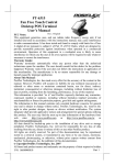
HT-4312
Series
PB-4300
User’s Manual
Rev. Original
FCC Notes:
This equipment generates, uses, and can
radiate radio frequency energy and, if
not installed and used in accordance with the instructions manual,
may cause interference to radio communications. It has been
tested and found to comply with limits for a Class A digital device pursuant to subpart J
of Part 15 of FCC Rules, which are designed to provide reasonable protection against
interference when operated in a commercial environment. Operation of this equipment
in a residential area is likely to cause interference in which case the user at his own
expense will be required to take whatever measures to correct the interference.
Warranty Limits:
Warranty terminates automatically when any person other than the authorized
technicians opens the machine. The user should consult his/her dealer for the problem
happened. Warranty voids if the user does not follow the instructions in application of
this merchandise. The manufacturer is by no means responsible for any damage or
hazard caused by improper application.
About This Manual:
Posiflex has made every effort for the accuracy of the content in this manual. However,
Posiflex will assume no liability for any technical inaccuracies or editorial or other
errors or omissions contained herein, nor for direct, indirect, incidental, consequential
or otherwise damages, including without limitation loss of data or profits, resulting
from the furnishing, performance, or use of this material.
This information is provided “as is” and Posiflex Technologies, Inc. expressly
disclaims any warranties, expressed, implied or statutory, including without limitation
implied warranties of merchantability or fitness for particular purpose, good title and
against infringement.
The information in this manual contains only essential hardware concerns for general
user and is subject to change without notice. Posiflex reserves the right to alter product
designs, layouts or drivers without notification. The system integrator shall provide
applicative notices and arrangement for special options utilizing this product. The user
may find the most up to date information of the hardware from web sites:
http://www.posiflex.com or http://www.posiflex.com.tw
All data should be backed-up prior to the installation of any drive unit or storage
peripheral. Posiflex will not be responsible for any loss of data resulting from the use,
disuse or misuse of this or any other Posiflex product.
All rights are strictly reserved. No part of this documentation may be reproduced,
stored in a retrieval system, or transmitted in any form or by any means, electronic,
mechanical, photocopying, or otherwise, without prior express written consent from
Posiflex Technologies Inc. the publisher of this documentation.
© Copyright Posiflex Technologies Inc. 2007
All brand and product names and trademarks are the property of their respective holders.
P/N: 15450900010
Part 1
ALERT TO OUR HONORABLE CUSTOMERS:
l Please always read thoroughly all the instructions and documents
delivered with the product before you do anything about it. Don’t
take any premature action before you have a full understanding of
the consequences.
l This product contains inside a Lithium battery and maybe also a
sealed type Lead acid battery if the UPS battery option is ordered.
Please always follow local environmental protection laws /
regulations for disposal of used batteries and always replace only
with battery of same type.
l If you have an UPS battery installed in the product:
² Temperature above 40°C must be strictly avoided as it
could cause termination of battery life and unexpected result
even if the battery is not in work.
² Do not power off the system just by shutting off the AC
power leaving the battery supporting the whole system till
completely exhausted. Repeatedly using it up or improper
maintenance reduces the battery life dramatically.
² Always fully recharge the battery at least once every 3
months if the battery is not connected.
² Always disconnect the UPS battery from the system if the
system is to be left OFF for more than 72 hours to prevent
possible damage. Only connect the UPS battery back right
before you are going to re-power on the system.
² Replace the battery as soon as the monitoring software
indicates the battery is out of service. Attempt to recharge a
dead battery is dangerous!
² A separate battery monitor is not required for this series.
DAILY MAINTENANCE GUIDE
For regular cleaning of the HT-4312/PB-4300 systems, please use
only soft haired brush or dry soft cloth. You may use moist soft cloth to
remove stains when necessary. Apply only proper amount of mild neutral
detergent for obstinate stains. Please note that never use Acryl dissolving
solvent or Polycarbonate dissolving solvent. You may apply ammonia-based
glass cleaner only on the screen surface.
Part 2
BRIEF INTRODUCTION
THE USER’S MANUAL
The purpose of this manual is to guide the user in the initial
installation and general use of the Posiflex HT-4312/PB-4300 series of POS
terminals. It does not explain any application software that may be supplied
with it.
We intend to provide our customers with all technology advantages
available by evolving the product design to incorporate appropriate changes
and improvements. So some detail differences may exist between this manual
and the equipment supplied.
For more detailed or technical information please refer to the CDROM disc associated or consult our authorized dealers or visit our web site:
http://www.posiflex.com.tw/ or http://www.posiflex.com/
THE PRODUCT
The Posiflex range of HT-4312/PB-4300 terminals have been
designed and manufactured to meet the high end demand on POS systems. It
incorporates all the advances of PC technology within a rugged housing
designed for use in a hostile retail environment. By providing an integrated
design, it has retained many of the secure features of a traditional ECR and has
avoided the wiring “spaghetti” associated with more traditional PC solutions.
This Open Standard Architecture ensures that this terminal can use the PC
application software and development tools that are now inexpensively
available and abundant.
For the HT-4312 series terminal is powered by most up to date CPU
and provides a color TFT LCD screen with a resistive type touch control panel
on sturdy and easily adjustable structure on top of the main unit. HT-4312/PB4300 series may be used as a self-content unit or as one of several terminals in
a network system controlled by a “back office” computer through the
integrated network interface. Versatile options besides the basic model
selection can apply to it too.
An optional integrated unit of MSR and/or Finger print sensor can be
installed in the HT-4312 system (side mount to LCD panel). The HT-4312/PB4300 system also provides an optional CF memory card slot and an optional
UPS function module that includes a CR port with status sensibility for
controlling 1 or 2 Posiflex printer drive type cash drawers and the most
advanced UPS functions to safeguard the POS operation against intermittent
power failure with another option UPS battery, careless touch on the power
switch, and to support unmanned remote account consolidation operation, etc..
Part 3
THE STANDARD FEATURES
CPU + Chipset: Intel Celeron 2.0 GHz + Intel 852GM or Intel P4 2.4 GHz +
Intel 852GME or above.
HDD: 40 GB or above.
RAM: 2 DDR DIMM, 256 MB.
Ethernet Networking: The standard network port works with both 10 Base T
and 100 Base T.
Serial Ports: There are 4 serial ports in a HT-4312/PB-4300 system. COM1 is
shared by the direct driven cash drawer port if exists. Each COM port is
capable of providing independently a +5 V DC or a +12 V DC supply. All
these DC supplies are achieved through internal jumper setting and they are all
defaulted to give no DC supply at delivery.
Parallel Port: Each HT-4312/PB-4300 system is equipped with a parallel port
that supports SPP/EPP/ECP.
VGA Port: There is a VGA connector for connection of external monitor with
+ 12 V DC power supply included. It is default as no power at delivery.
USB Ports: The HT-4312/PB-4300 series is equipped with 5 USB type A
connectors for connection of USB (Universal Serial Bus) devices. For HT4312 series one of the 5 ports is extended to one top edge of case for easy
connection to the integrated upgrade kit BC-300 or SD-300.
PCI Slot: 1 PCI extension slot if no powered USB or UPS option installed.
Modem Ring-Up, LAN Or Alarm Wake-Up: The HT-4312/PB-4300 series
can be turned on automatically upon an incoming COM port Modem call or
LAN status or data packet received on LAN or a preset time/day/week/month.
THE OPTIONAL ITEMS
Note: Underlined items below must be installed prior to delivery from factory.
Attempt to apply them by end users is either too difficult or is likely to cause
damages. Italic items below are stand alone peripheral devices.
a) Memory Expansion: Upgrade up to 2GB max.
b) 2nd HDD: 2.5” IDE interface
c) Compact Flash Memory Card Slot: Type I
d) Audio Amplifier and Internal Speaker: This option can be available
only in systems equipped with PCI riser card.
e) Side Mount Integrated Upgrade Kit for HT-4312 only: (BC-300)
Bar code card reader or (SD-300): This item contains options of a
Magnetic Stripe Reader with choice among 2 tracks or 3 tracks in ISO
standard or JIS I/II (JIS MSR for factory upgrade only) and an optical
type Finger Print Sensor
f) Customer display: Pole mount 2 x 20 VFD or LCD display or graphic
LCD pole display
g) 2nd Screen for HT-4312 or LCD Monitor for PB-4300: LM-2010, 10”
Part 4
TFT color LCD
Wireless LAN Adaptor: inside back cable cover, IEEE 802.11b/g
Preload OS: Win 2000, Win XP pro or WEPOS.
Powered USB Port: 2 ports for +12 V and +24V support separately.
Selecting this option will deny the PCI slot extension and the UPS
option.
k) UPS Function Module with CR Port: The most advanced UPS
functions to safeguard the POS operation against intermittent power
failure with another option UPS battery, careless touch on the power
switch, unmanned remote account consolidation operation, etc.
Selecting this option will deny the PCI slot extension and the powered
USB option.
l) UPS Battery: 2.3 AH 12V lead acid maintenance free battery
m) 2-in-1 Cash Drawer Control Cable: Cable CCBLA-238, when added
to the optional CR port of the HT-4312/PB-4300 series, can be used to
control two Posiflex printer drive type cash drawers.
n) Cash drawer: Printer (Direct) drive type Posiflex cash drawers. Model
numbers coded as CR-2000, CR-2200, CR-3100, CR-3200, CR-4000,
CR-4210 or CR-6200
o) Programmable Keyboard: Various types of Posiflex programmable
keyboards. Most recommended: KB-6000, KB-6200 series or KB-6600.
p) Bar Code Scanner: Short range type (near contact) and long range type
(250 mm for CD-3830) CCD scanners.
q) POS printer: Posiflex 9 pin dot matrix impact printer or Posiflex
thermal printer of RS232 serial interface, parallel interface, USB
interface or even wireless interface.
h)
i)
j)
SYSTEM BOX CONTENTS
When you receive the system box you will find it contains several items:
l HT-4312 system unit with the 12.1” LCD panel integrated on top or
PB-4300 system unit.
l This user’s manual
l Recovery CD or DVD for preloaded OS or Posiflex Product
Information CD or DVD for driver utilities without OS
l Optional components installed to system unit as ordered
l Main power cord (1 piece)
Part 5
INSTALLATION GUIDES
IMPORTANT
Please do not connect the power cord or turn on the main unit until
you have fully read the installation guides and followed the instructions!!!
TECHNICAL ENHANCEMENTS
Applicable technical enhancements in HT-4312/PB-4300 series
include serial COM port power supply settings, RTC battery replacement,
VGA port power supply setting, DRAM upgrades and adding a half length PCI
adapter card (This item is possible only when no powered USB port option
installed). All these technical enhancement operations require purchase of
applicable Technical Manual from Posiflex or consultation from Posiflex
authorized dealers and should be handled only by a qualified technician.
NON-USER-INSTALLABLE OPTIONS
When the HT-4312/PB-4300 system is ordered with options like
expanded system memory, 2nd HDD, CF memory card reader slot, powered
USB ports, or UPS function module, the option(s) is (are) already installed in
the system delivered. Therefore, no more installation is required. However,
please note that when the powered USB ports option is installed, adding a halflength PCI extension card will no longer be possible.
HALF LENGTH PCI EXTENSION CARD
If the HT-4312/PB-4300 system is not installed with the powered
USB ports option, adding a half-length PCI extension card is possible.
However, the whole operation will involve cautiously accessing the interior of
the system, replacing the slot window metal plate, applying the card and
installing its driver. Therefore, only a computer expert can perform this
operation on his own risk.
MAIN CONNECTION AREA
The HT-4312/PB-4300
maintenance. Press inward both
plastic buttons at lower rear
corners on both sides of the
system unit (circled in right
picture) to release the lower part
of back cable cover. Please note
that there are 2 plastic hooks on
top cover holding the back cable
cover as marked on upper part of
the picture. Carefully release the
back cable cover from the hooks
series is constructed for very easy
Push This Button
and also The One
on The Other
Side to Open
Cable Cover
Part 6
to show the main connection area.
Note: Never press the 2 springs on the metal walls as cross marked in the
picture. Carelessly pressing on these 2 springs could cause damages. The user
shall be responsible for such kind of damage. For the HT-4312 system even
the maintenance technician must always put a piece of clean flat foam of
sufficient size in front of the system unit before pressing these 2 springs. The
LCD and touch panel may flip forward by gravity and get or cause damage by
hitting anything in front of the system unit. For the PB-4300 system the
maintenance technician must always pay attention to always disconnect all
power and cable connections before pressing the 2 springs and not to cause any
damage either in the top cover opening operation after pressing the 2 springs or
by leaving or spilling any improper materials inside after the opening operation.
WIRELESS LAN (OPTION)
When the wireless LAN option is ordered with the HT-4312/PB-4300
system, this option is already installed in the delivery inside the back cable
cover with its cable connected to one of the USB port. This cable must be
disconnected first if installed whenever the back cable cover is opened for
any operation.
UPS BATTERY (OPTION)
UPS Battery Compartment
When
the
HT-4312/PB-4300
system is installed with the UPS battery
(with also an option of UPS function
module), the UPS battery is in the carton at
delivery. Please take it out and place it in the
battery compartment at center upper part of
UPS Battery Connector
the connection area indicated as upper
rectangle in picture at right. Connect the cable to its connector in the main
connection area beneath the battery compartment only when the system is
about to power up for operation. Always disconnect the UPS battery when
the system is to be left powered off for more than few days. Please pay
particular attention to the environment requirement for UPS battery in next
chapter “USING THE HT/PB SYSTEM”.
LCD CASHIER DISPLAY (for HT-4312 only)
Push down the round plastic
Push inward to
button at rear of the display base as
turn left-right
circled in right picture to adjust the
display up and down. Release the button
Push down to
when done will lock the panel firmly for
turn up-down
application. Pushing the rectangular
shape plastic button to its right toward the base center allows user to adjust the
display horizontally for best view angle.
Part 7
10” 2ND DISPLAY (OPTION)
When the HT-4312 series is ordered with the 2nd
display monitor LM-2010 or when the LM-2010 is ordered
for PB-4300 to work as the primary monitor, the monitor
will be delivered in separate package from the system unit.
Please follow the Installation Guide in package of the
option. Then please open the system unit and set the +12V
DC supply in the VGA connector under technical guidance
from your distributor.
CUSTOMER DISPLAY (OPTION)
When the HT-4312/PB-4300 series is ordered
with the customer display PD-2601/2601U, PD-307/307U
or PD-7622 option, the customer display together with the
pole for installing them to corner of back cable cover will
be delivered in separate package from the system unit.
Please follow the Installation Guide in package of the
option. The customer display will occupy one USB or
COM port in the connection area. Consult your distributor
for technical support on setting up the +5V DC supply to
the COM port used if the customer display is of the serial interface type.
When the 2nd screen is installed on HT-4312, the operation of a PS/2
interface mouse will be limited in the area of 1st screen. Please use an USB
interface mouse for dragging icon to 2nd screen if required.
SIDE MOUNT UPGRADE KIT (SD-300/BC-300 Option for HT-4312 only)
When a side-mount upgrade kit option SD-300 or BC-300 is ordered
with the HT-4312 system, this option is already installed
in the delivery. No matter the kit itself contains MSR
only, finger print sensor only or both options, the
connection to the HT-4312 system is one USB cable
inserted to the extended USB port at top right edge of the system unit as
circled in the upper picture at right.
After removing the plastic cover by pushing it side way,
the extended USB port can be found as marked in the lower
picture at right.
The USB cable from the optional
side mount upgrade kit SD-300 or BC-300
should be inserted in the cable hook on
back of LCD panel as circled in left picture.
Part 8
AUDIO PORT
The audio output port must be connected to either the earphone or a
pair of speakers with booster or amplifier if used. When the audio amplifier
option is installed, there will be an internal speaker inside the main unit with
amplifier constructed on the internal PCI riser card.
PROGRAMMABLE KEYBOARD (OPTION)
All types of Posiflex programmable keyboards can be applied in HT4312/PB-4300 system. Most recommended models are: KB-6000, KB-6200
series and KB-6600. Just connect it to the PS/2 KB port in the main connection
area. The application of the keyboard requires no software driver and is free
from any software compatibility issue. The system integrator can program the
content of the keyboard for the application software following the technical
guidance of Posiflex keyboard programming utilities.
BARCODE SCANNER (OPTION)
Modern barcode scanners applied in POS business are of KB interface
type. Most of them provide both a male and a female PS/2 KB connector.
Therefore it can be connected either to the bottom of the Posiflex
programmable keyboard with the cable fit into the strain relief groove or in
between the PS/2 KB port of the system unit and the Posiflex programmable
keyboard. The only consideration is that in programming stage of the
programmable keyboard, nothing (including the barcode scanner) should come
in between the system and the programmable keyboard. However, this should
be no problem in application phase.
When a KB interface barcode scanner is installed in HT-4312/PB4300, a connection of a normal PS/2 keyboard or the Posiflex programmable
keyboard could become obligatory by some OS. Therefore, if there will be no
keyboard installed for such OS, it is advisory to use an USB interface type
barcode scanner instead of the PS/2 KB interface type.
PRINTER (OPTION)
There are many models of Posiflex POS printers that can be applied
in HT-4312/PB-4300 system. These printers cover several interface
technologies. Please connect the printer to a COM port, the LPT port or an
USB port in the main connection area depending on the printer model and then
connect its power adaptor. It is also possible to control a Posiflex wireless POS
printer by connecting a separately purchased wireless Dongle to one of the
COM ports in HT-4312/PB-4300 system.
CASH DRAWER (OPTION)
The RJ11 connector in main connection area of a HT-4312/PB-4300
system can be used for controlling most of the common cash drawers available
on the market only if the UPS function module option is installed. However,
Part 9
it is most recommended that the Posiflex CR-2000 or CR-2200 or CR-3100 or
CR-3200 or CR-4000 or CR-4100 or CR-4210 or CR-6200 be used for best
compliance.
The HT-4312/PB-4300 system will directly control the cash drawer
using the cash drawer port (CR) both to operate the opening mechanism and to
monitor the drawer open status. Both functions may be accomplished under
software control of the COM1 serial port.
Use the cable supplied with the cash drawer (Part No. 21863018010)
for connection to the CR port in HT-4312/PB-4300 system. This cable has a 6pole plug at one end and an 8-pole plug at the other. The 8-pole plug should be
inserted into the connector marked: “signal cable from POS Printer” at the rear
of the cash drawer. The 6-pole plug should be inserted in the connector marked
“CR” found in the main connection area in the system.
The user may also use the optional 2-in-1 cash drawer control cable
CCBLA-238 to control 2 cash drawers in 1 port. It has a 6-pole plug at one end
and two 8-pole plugs at the other. The 6-pole plug should be inserted in the
connector marked “CR” found in the main connection area in the system. Each
8-pole plug should be inserted into the connector marked “signal cable from
POS Printer” at the rear of one of the cash drawers. The cable lengths for the
two 8-pole plugs are different. Use the shorter one for the original cash drawer
“CR1” and use the longer one for the extended cash drawer “CR2” that will be
distinguished by the software command.
AC POWER
The power supply operating voltage must be checked to support the
city power supply specification and switch selected if necessary. This must be
done WITHOUT any connection to the AC power.
The operating voltage selection switch is located close to the power
input connector in the main connection area inside the back cable cover.
The switch should indicate either 115 volts or 230 volts. When set at
115 volts the acceptable power supply voltage range is 103 volts to 122 volts
whilst at 230 volts the acceptable power supply voltage ranges from 207 volts
to 244 volts.
The power supply cable should first be connected to the power inlet
(but NOT the wall socket). This cable should be consolidated with other cables
and come out of the connection area through the bottom opening of the chassis.
OPERATING SYSTEM RECOVERY
The operating system exists in the HDD in top of the system unit.
Once the software system on HDD collapses, it is possible to restore the
operating system onto a physically intact HDD with use of the Recovery CD or
DVD that comes with the preloaded operating system. Please follow the
instruction from your system integrator for system / software restoration.
Part 10
Follow the instructions below for operating system recovery only if your
system integrator does not advise otherwise.
For the HT-4312/PB-4300 system preloaded with Windows system on
HDD, Posiflex provides recovery CD or DVD delivered with the hybrid
terminal for the preloaded operating system. The System Integrator shall take
care of software restoration after OS recovered. Use a Posiflex supplied USB
interface external CDROM or COMBO drive for such action. Other brand
CDROM or COMBO drive may require its specific driver different from what
supported in the recovery CD or DVD.
Please use the recovery CD or DVD in rescue operation only.
Using it otherwise may wipe out whatever stored in the HDD! All upgrade
devices drivers needed for manual installation in usual way are available in the
subfolder “\drivers” in OS recovered HDD and the latest versions of these
required drivers will be available on our web: http://www.posiflex.com or
http://www.posiflex.com.tw.
Now please follow instructions from your system integrator for
software recovery after OS recovery and driver installation.
OPERATING SYSTEM INSTALLATION
This product is highly professionalized equipment. The installation of
an OS into a machine without any preloaded OS could constitute major
difficulty for average user who either has barely limited technical knowledge
of this professionalized equipment or is insufficiently equipped with necessary
facilities to accomplish such a task. Therefore, installation of an OS into a
system without preloaded OS is highly discouraged. Posiflex shall not be
responsible for any technical support to questions arisen due to non-preloaded
OS.
Part 11
USING THE HT/PB SYSTEM
BEFORE POWER ON – A Check List
It is very important that you check the following operational points:
Ventilation
This terminal must NOT be operated in an environment with
restricted ventilation. There must be at least 25 mm air clearance around any
top or side ventilation holes with a free flow of air around the unit at ALL
times for the installation.
Operating Environment
The equipment must not site in direct sunshine, near a heater or in a
damp and must be free from contaminants like dust, smoke or fume.
The equipment must not be operated or stored in extremes of both
temperature and humidity/moisture.
(Operating range 0°C to + 35°C and up to 80% relative humidity –
non condensing max. wet bulb 26°C)
Power Supply
The operating voltage of the power supply should be checked to
confirm that it is set within the range of the local power supply. The power
cable, the power outlet and any power fusing arrangements must conform to
local safety regulations.
UPS Battery (option)
General care:
The UPS battery is consumable beyond product warranty. Please
definitely observe the alerts in beginning of this manual. If the equipment is to
be powered off for more than few days, please always disconnect the battery
from the system. Reconnect it and turn on the system to recharge the battery
for 1 ~ 2 hours every 3 months for temperature lower than 30°C. Recharge for
1 ~ 2 hours every month for temperature over 30°C. Temperature above 40°C
must be strictly avoided as it could cause termination of battery life and
unexpected result even if the battery is not in work. The UPS battery can
support basically the data preservation and smooth running of the system
during intermittent or few minutes (2 ~ 6 min. depending on loading and
battery condition) power failure if the UPS function module option is installed.
Battery replacement:
In the preloaded OS for a HT-4312/PB-4300 series with UPS function
module option, there is a built in utility Posiflex
Power Switch Manager that will indicate the UPS
battery status of the battery. When an installed UPS
battery is found to be disabled or when pop up
Part 12
warning message like this picture appears, please replace the used up UPS
battery at power off as soon as possible.
Emergency treatment:
The battery is constructed maintenance free and leakproof. Its storage
space in HT-4312/PB-4300 system also provides very good protection as long
as the ambient temperature remains below 30°C and the ventilation of the HT
system remains free. However, should any accident happen and the sulfuric
acid from the battery spills on skin or clothing, wash immediately with water.
If the acid comes in contact with eyes, rinse eyes with large amount of clean
water and see a doctor immediately. A larger external battery may be
connected to give an extended operation. Please check your dealer about this
capability when required.
WARNING:
If there are any signs of over charging or leakage of electrolyte
please contact your dealer immediately
VGA Display Port
The VGA port in the HT-4312/PB-4300 terminal supports a 12 volt
DC power to the external (secondary) monitor through the VGA signal cable
after proper internal jumper setting change. This may cause permanent damage
to any other monitor not designed to use this facility. Please use only a
Posiflex monitor designed for the HT system. Consult your dealer if you have
any doubt. It is strongly advised that connection/disconnection to this port
should never take place when system power is ON.
(Note: 12 volt DC power is available on pin 9 of the VGA connector and
is supported by the UPS function if the UPS function module option is
installed.)
The video memory of this port shares from the system memory. The
video memory size can be set in the BIOS CMOS setting to match the user’s
application.
Serial Port – COM1
If the HT-4312/PB-4300 system is installed with the UPS function
module option, a COM1 terminator will also be supplied. Please always
occupy COM1 serial port by a suitable serial device or this terminator. If this
port is left vacant or connected with something like a mouse, the power switch
management and the cash drawer control (when UPS function module option
is installed) may fail to work correctly. An RS232 MODEM is not applicable
to this port. It is recommended to use COM2, 3 or 4 instead.
LED INDICATORS (for HT-4312 only)
On bottom rim center of HT-4312 system cashier LCD panel, there
are 2 LED indicators. The LED at right indicates the LAN status. When it
Part 13
lights up in green, the onboard LAN chip is linked. When it flashes in yellow,
data transmission in LAN is in process. The LAN status indication is also
observable on the LAN connector in main connection area. The LED at left
indicates Power/StandBy status. When it lights up in orange, it means that the
external AC power is standing by with the system powered off. It turns into
blue when the system is powered up. When the UPS function module option
and the UPS battery are installed, this LED further indicates the status of
system working on battery power by flashing in blue. The blue light will flash
rather fast when the UPS battery approaches a fully discharged condition to
remind the operator that power will soon finish. In few seconds, the whole
system will soon be automatically turned off and the LED will be OFF. In case
the AC power resumes during the usage of the battery power, the flashing LED
will keep on flashing for few seconds before steady till the AC supply is stable.
POWER ON/OFF CONTROL
The HT-4312/PB-4300 terminal implements electronic power control,
such that the main power to the system may be controlled by many methods as
below:
1. Hardware power switch
2. Software OFF command
3. Automatic power ON control
4. Emergency power OFF
Switching from OFF to ON requires a normal supply of the AC power.
Hardware Power Switch
This button is located at bottom front corner of
right side as in right picture and can be used to turn the
system on and off alternatively if no optional UPS
function module installed. When this option is installed,
this hardware switch can also be programmed to be an ON only switch through
software command so that when this switch is accidentally pressed during
system turned on, the system just remains on and unaffected.
Software Off Command
The system may also be shut down under software control if the
optional UPS function module is installed. Please just follow the arrangement
by your system integrator for this capability.
Automatic Power On Control
The system may also turn on according to some preset conditions
such as Modem Ring Up and Alarm Clock Wake Up or LAN Wake Up.
To utilize Modem Ring Up or Alarm Clock Wake Up function, the
user should enter the CMOS setup by pressing “Del” key at system boot up,
choose for “PM Wake Up Events” in “Power Management Setup”
Part 14
and make the “Ring Power Up Control” enabled for Modem Ring Up or select
the “Power Up by Alarm” for Alarm Clock Wake Up. Save the configuration
and exit the CMOS setup program. The Preset Power On Control will then be
ready after a normal power off. For LAN wakeup, an operating caller system
connected through LAN to the system is required. It also requires a qualified
networking technician to check the LAN chip ID of the HT-4312/PB-4300
system for the caller system to wake it up.
When the HT-4312/PB-4300 system is turned off after a successful
boot up, the preset automatic power on functions will keep monitoring for the
preset conditions and turn on the system when the preset conditions are met.
Please note that if the HT-4312/PB-4300 system is improperly turned
off before a complete boot up procedure, the above preset power on control
functions will be disabled until next turning off after a complete boot up.
Emergency Power Off
In case of serious system halt due to any reason, the system could fail
to be powered off through normal means. Press and hold the Power ON/OFF
Switch for Emergency Power Off. Release the switch after the system powered
off. It will take about 4 seconds if no UPS function module installed and it
takes about 10 seconds if the option installed. If there appears to give a special
coded beep tone in the pattern “short, long, short, long, short” prior to the
system power off in this process, please remove the AC power and wait for
few minutes to allow the hardware registers to reset (If there is no such beep,
AC removal is not required). Then you may restart the system and take
remedial action against the precious failure.
MAIN LCD TOUCH MONITOR (for HT-4312 only)
Mechanical Adjustments
The 12.1” LCD color display is integrated on display platform to give
the operator the clearest view. The inclined angle of the display may be
adjusted from 15° to 50° and rotated from straight forward to 16° to the left.
Display Controls
On lower left edge of back of the LCD panel
there is a plastic wheel knob as circled in the picture at
right. Turning this knob up or down changes the
brightness of screen display accordingly.
Display Utility Driver
The end user of the HT-4312 terminals is not supposed to install the
utility drivers personally. If an optional preloaded OS is ordered, the required
driver will be already installed in the preloaded OS. However, the driver will
always be available over our web site: http://www.posiflex.com
Part 15
Touch Function
Mouse emulation
The touch panel in HT-4312 system works exactly like a standard
PS/2 mouse within the (primary) screen display area when its driver is
properly installed. However, if the system is running under safe mode due to a
previous improper shutdown or for any other reason, most drivers are disabled
in this mode and the touch panel calibration may not coincide with the mouse
pointer or even completely out of work. It is recommended to use an USB
mouse or USB keyboard in safe mode.
All the below mentioned mouse emulation functions in the primary
display area can be manipulated through relevant software. The system can
give a beep when the touch panel is touched and can respond as if the left
button of a mouse is clicked at the point touched. If the point touched is
dragged across the screen surface, it can respond as if it is using the mouse
drag and drop feature. If the point is touched, released and touched within a
short time interval, it will simulate double-clicking left button of the mouse.
Emulating the click on right button of a real mouse is further illustrated in
paragraph below.
Touch terminal manager
Before using the PS/2 interface resistive type touch control panel, one
must be aware that if you connect any monitor to the VGA port of HT-4312
system for extended secondary display application, you can not apply any
touch control function for this secondary display due to driver conflict
concerns! The operation range of a PS/2 mouse is also limited within the
primary display area.
A program named “Posiflex Touch Terminal Manager” is installed in
the preloaded Windows system for the user to maneuver versatile features of
the touch terminal with a PS/2 interface touch panel controller. This program
can also be obtained by download from the POSIFLEX web site. However, the
installation process of this driver for Win XP and Win 2003 Server requires
some careful attention to the notice messages.
With proper setup and selection on control items in “Posiflex Touch
Terminal Manager”, a drawing representing a 2-button mouse will appear on
the desktop. Touch the right button in this drawing. Any touch on the screen
after this action will result in a right button mouse click at the point touched.
After touching the left button in this drawing the screen touch will resume the
left button function. This program also controls the beep generated when the
touch panel is touched, the detail in right button click emulation, and also
provides touch panel re-calibration. In principal, the touch panel requires no
further calibration once properly set.
USB touch manager
A program named “Posiflex USB Touch Manager” and a right-click
Part 16
sticky button tool in the program group “Posiflex USB Touch Tools” is
installed in the preloaded Windows system if a USB interface touch panel
controller is installed.
CUSTOMER DISPLAY
The optional customer display mounted on a pole at rear corner of
HT-4312/PB-4300 system can be turned horizontally for best viewing effect in
application.
SIDE MOUNT UPGRADE KIT SD-300 (for HT-4312 only)
In SD-300 mounted at right side of the touch monitor of HT-4312
system, there may be the MSR for reading a magnetic stripe card and/or the
optical type finger print sensor. For magnetic stripe card reading, be sure to
insert the card to the bottom with magnetic stripe facing the mark aside the slot.
The movement of the card can be either inserting the card from the top surface
then sliding the card down out of the slot, or sliding the card upward from the
lower side of the slot till it reaches the top end as long as the card is a standard
one. A non-standard card recorded without complete degaussing prior to
recovery may accept only one direction in card reading.
USB
There are five standard USB female connectors in the rear room. All
support the Universal Serial Bus Specification standard 2.0 and also 1.1. If for
any reason (though very unlikely in ordinary practice) these ports has to be
limited as USB 1.1 only, please enter BIOS setup and go to “Integrated
Peripherals” then “Onboard Device” and disable the item “USB 2.0
Controller” and enable it back afterwards
If the powered USB ports option is installed in the HT-4312/PB-4300
system, please be sure to insert the USB device always to the exactly correct
type of the connector.
VENTILATION MAINTENANCE
To keep this equipment in orderly service, following maintenance
should be performed on a regular basis.
Removing Front Cover
Please first remove any power and signal connection to this
equipment. Please then check at the bottom side of the chassis that there is a
gap between the bottom side of front cover and the chassis at the left corner of
front cover. Pull the front
Front Cover
cover out from this opening to
release the left side hook of
Release Opening
front cover from the chassis
as indicated by the hollow
Chassis Bottom View
arrow in the right picture.
Part 17
Please then pull the bottom side of front cover
forward to release the bottom hooks of front cover from the
chassis as indicated by hollow arrow in left picture.
Now pull the left side of front cover down a little
to free it from the main cover as in the pictures below.
PB-4300
HT-4312
It may be required to push the power switch
down to completely remove the front cover.
Power Switch
Cleaning for Front Ventilation
Use vacuum cleaner to remove any dust or threads accumulation
away from both the ventilation holes on front cover and ventilation grids on
chassis exposed after removal of the front cover.
HT-4312
PB-4300
Front Ventilation Grids on Chassis
Ventilation Holes on Front Cover
Part 18
Replacing Front Cover
Follow the opposite procedure as removing the front cover to replace
the front cover in position. Please make sure the all hooks on front cover is
well positioned into chassis. Please remember to check that the power switch is
at “Off” position before power and signal connection.
Accessing Side Ventilation Grids
The operation to further clean the side ventilation grids requires much
more highly technical maneuver. Therefore careful attentions must be taken
throughout the further cleaning operations below. When the main unit is
opened, there must be no liquid spill, no electro-conductive material, no
electric charged device come into the area of the main unit. Please also note
that not to touch any component or cable inside.
Please first disconnect every
cable from the main unit and for the
HT-4312 turn the LCD panel to straight
up position. Prepare enough space in
front of the HT-4312/PB-4300 system Push The
and lay a piece of clean soft clothe of Spring
appropriate size there to prevent damage. Buttons on
With the back cable cover opened, push Both Sides
in the circled spring button in the right and Raise
picture on both sides of chassis and The Rear Part
raise the rear edge of the top cover. of Top Cover
Apply some mild maneuver if there is
already a pole display mounted.
Cleaning for Side Ventilation
Use vacuum cleaner to remove any dust or threads accumulation
away from outsides of both ventilation grids on chassis exposed after removal
of the front cover as in pictures below and close back the top cover when done.
Side
Ventilation
Grids on
Chassis
Part 19
警告使用者
T31454
這是甲類的資訊產品,在居住的環
境中使用時,可能會造成射頻干
擾,在這種情況下,使用者會被要
求採取某些適當的對策。
Part 20