1
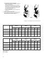
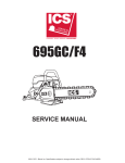
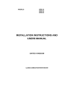
MODELS
ADMP
ADMP
ADMP
ADMP
ADMP
ADMP
40 G
50 G
60 G
80 G
90 G
115 G
INSTALLATION INSTRUCTIONS
AND USER'S MANUAL
UNITED KINGDOM
WATER HEATERS
FOREWORD
Before attempting to install this water heater please read the installation instructions. Read the user’s manual before first
igniting the heater. Failure to follow these instructions meticulously could lead to risk of an explosion and/or fire and can
cause material damage and/or physical injuries.
An accredited installer must install the heater and commission it for the first time. The type of gas and the values are preset (ex works) and are given on the model plate. The heater may only be installed in an area of which the available
clearances comply with the required ventilation regulations.
The ADMP models are fitted with a permanent pilot light.
A.O.SMITH CANNOT ACCEPT ANY RESPONSIBILITY FOR GUARANTEE, SERVICE AND/OR PRODUCT LIABILITY IN THE
EVENT OF UNAUTHORISED CHANGES, PRODUCT MODIFICATIONS OR REPAIRS.
2
CONTENTS
PAGE
PILOT-LIGHT HEATERS (modellen ADMP 40 t/m 115)
1
1.1
1.2
1.2.1
1.2.2
1.2.3
1.3
1.3.1
1.3.2
GENERAL
Description of the heater ................................................................................................................ 4
Technical safety equipment ............................................................................................................ 5
Gas control block ............................................................................................................................ 5
Control box ...................................................................................................................................... 5
Thermal reflux safeguard (TRS) ..................................................................................................... 5
Technical description ...................................................................................................................... 6
Dimensions .................................................................................................................................... 6
Technical data ................................................................................................................................. 8
2
2.1
2.1.1
2.1.2
2.1.3
2.1.4
2.1.5
2.1.6
2.1.4
FOR THE INSTALLER
Installation instructions ................................................................................................................. 10
Installation ..................................................................................................................................... 10
Water connection .......................................................................................................................... 10
Gas connection ............................................................................................................................. 12
Flue system ................................................................................................................................... 12
Flue-gas discharge ....................................................................................................................... 12
Thermal reflux safeguard (TRS) ................................................................................................... 13
Electrical connection ..................................................................................................................... 13
2.2
2.2.1
2.2.2
2.2.3
2.3
2.4
2.5
2.6
2.7
2.8
2.9
2.10
2.11
Commissioning ............................................................................................................................ 14
Filling the heater ........................................................................................................................... 14
Commissioning ADMP models .................................................................................................... 14
Setting the pilot light ...................................................................................................................... 14
Shutting down ............................................................................................................................... 14
Operation/temperature control ..................................................................................................... 14
Setting the nominal loads ............................................................................................................. 15
Conversion to another gas ........................................................................................................... 15
Maintenance .................................................................................................................................. 17
Anode ............................................................................................................................................ 17
Deliming ........................................................................................................................................ 17
Condensation ............................................................................................................................... 17
Spare parts ................................................................................................................................... 17
3
3.1
3.1.1
3.1.2
3.1.3
3.2
3.3
3.4
FOR THE USER
Instructions for use ....................................................................................................................... 18
Warning ......................................................................................................................................... 18
Filling the heater ........................................................................................................................... 18
Commissioning ADMP models .................................................................................................... 18
Operation ...................................................................................................................................... 18
Shutting down ............................................................................................................................... 18
Maintenace .................................................................................................................................... 18
4
4.1
4.1.1
4.1.2
4.1.3
4.1.4
4.2
WHAT TO DO IN CASE OF A FAILURE
General ......................................................................................................................................... 19
Overheat thermostat ..................................................................................................................... 19
Thermal Reflux Safeguard (TRS) ................................................................................................. 19
Wrong hot water temperature ....................................................................................................... 19
Water temperature too high .......................................................................................................... 19
Fault overview ................................................................................................................................ 20
5
WARRANTY
Garantee in general ...................................................................................................................... 21
Garantee of the tank ...................................................................................................................... 21
Conditions for installation and use .............................................................................................. 21
Exclusions ..................................................................................................................................... 21
Range of the quarantee ................................................................................................................ 21
Claims ........................................................................................................................................... 21
No other quarantee or warranty either expressed or implied is made on behalf
of A.O. SMITH WATER PRODUCTS COMPANY ........................................................................... 21
5.1
5.2
5.3
5.4
5.5
5.6
5.7
Appendix 1 Electrical scheme ADMP-models ................................................................................................. 22
3
PILOT LIGHT HEATERS (MODELS ADMP)
1.
GENERAL
1.1
Description of heater
Construction methods and equipment of the heaters are
in accordance with the European standards for gasfired
hot water heaters for sanitary use (EN 89). The heaters
are therefore comply with the European Guidelines for
Gas Heaters and are therefore permitted to carry the CE
hallmark. These are open flued heaters without
mechanical ventilator, with a Thermal Reflux Safeguard
(TRS) (heater category B11BS ). The heaters are suitable
for use with a working pressure of up to 8 bar.
The cylindrical tank is made from sheet steel containing
a number of vertically placed flue tubes. For protection
against corrosion, the inside of the tank is enamelled.
The tank is also fitted with a number if magnesium
anodes for extra protection against corrosion. A thick PU
insulating layer between the tank and the steel jacket
helps to reduce unnecessary heat loss.
1
2
3
4
5
6
7
8
9
10
11
12
13
14
15
16
17
18
19
20
When the heater is completely filled with water, it is
under continual mains water pressure. When hot water
is drained from the heater, cold water immediately
enters the heater. For effective heat transfer flue baffles
have been included in the flue tubes. Heat from the fluegases is transferred to the water by means of radiation
and convection. The flue-gases are guided to the
chimney via a rotateable and removable draught diverter.
Flue-gases are discharged by thermal draught.
The atmospheric burner consists of a number of bar
burners. One injector is screwed into the manifold for
each bar burner. The function of the injectors in the inlet
venturi ensures a good mixture of gas and primary air.
Secondary air is drawn in between the bar burners. The
permanent piliot light ensures that the burner ignites as
soon as there is a demand for heat.
A radiation shield is fitted beneath the burner which also
serves to collect any condensate (see diagram 1)
Draught diverter
High-limit and overheat
thermostat sensors
Hot-water outlet
Thermostat sensor
Control box
Cold-water inlet
Drain cock
Thermocouple
Pilot burner
Gas control block
Flue-pipe connection
Covering plate for flue-damper
assembly
Support for draught diverter
T&P connection (temperature
and pressure valve)
Anode
Flue tubes
Flue baffles
Insulation
Bar burners
Radiation shield/condensate
tray
Diagram 1- Cross-section ADMP-models
4
1.2
TECHNICAL SAFETY EQUIPMENT
1.2.1. Gas control block
the heaters are equipped with a gas control block which
regulates the flow of gas to the burner. The gas control
block is equipped with a safety valve, gas control valve,
pilot light pressure control and burner control (on a
standard natural gas setting). The safety valve is
controlled by the millivoltage generated when the
thermocouple is heated by the permanent pilot. To
ensure improved ignition the gas control valve opening
mechanism is fitted with a delay (softlite).
The control box is fitted with an ON/OFF switch (I/O).
At setting I, the gas control block is controlled on the
basis of heat demand from the control thermostat. At
setting O the heater is switched off.
1.2.3. Thermal Reflux Safeguard
The heater is equipped with a Thermal Reflux Safeguard
(TRS), which consists of a temperature sensor and
thermostat fitted to the draught diverter. The function of
the TRS is to switch off the heater if flue gases pass
through the draught diverter and enter the area in which
the heater is installed instead of being expelled via the
chimney.
1.2.2. Control box
Temperature control for the water heater is housed in
the control box. For safety purposes, heaters are always
filled with three thermostats: a control thermostat, a
high-limit thermostat and an overheat thermostat. The
desired water temperature is set with the control
thermostat. The overheat thermostat prevents the water
reaching too high a temperature.
Diagram 2- Control box ADMP-models
Should both control and high-limit thermostats
malfunction, the overheat thermostat will automatically
shut down the heater. The overheat thermostat breaks
the thermocouple circuit, which closes the safety valve,
cutting of the supply of gas to the pilot burner which
extinguishes the pilot light.
The control thermostat can be set at settings 1-4
(approx. 40ºC to 73ºC). the switch temperature of the
high-limit thermostat is 84ºC; the overheat thermostat
cuts in at 93ºC. The sensor for the control thermostat is
located at the level of the control box; the sensors for the
high-limit and overheat thermostats are located near the
top of the heater.
5
1.3
TECHNICAL DESCRIPTION
1.3.1 Dimensions (see diagram 3)
The heaters must be connected to a flue with a
minimum of the prescribed diameter (see size G).
Connection to a pipe of a larger diameter by means of a
coupling is permitted.
Size
ADMP 40
ADMP 50
ADMP 60
ADMP 80
ADMP 90
ADMP 115
A
1900
2100
1900
2100
2000
2085
B
1760
1960
1760
1960
1795
1870
D
710
710
710
710
710
710
E
800
800
800
800
800
800
F
1100
1100
1100
1100
1105
1105
G
150
150
180
180
225
225
H
660
660
660
660
675
675
J
1840
2040
1840
2040
1935
2010
K
205
205
205
205
205
205
L
400
400
400
400
400
405
M
565
565
565
565
575
650
N
1605
1810
1605
1810
1640
1715
P
730
730
730
730
740
825
R
500
515
500
515
525
600
S
1550
1760
1550
1760
1595
1660
1
Cold water inlet
2
Hot water outlet
3
Gas control block
4
Drain cock
5
T&P-connection (temperature and pressure valve)
6
Covering plate for inspection hatches
All measurements are given in millimetres (rounded off to the nearest 5 mm).
6
Diagramm 3 - dimensions ADMP
7
1.3.2. Technical data
Heater categorie II2H3+
DESCRIPTION
Unit
ADMP 40
ADMP 50
ADMP 60
ADMP 80
ADMP 90
ADMP 115
Nominal input (lower value)
kW
38.0
50.9
59.8
74.3
88.5
114.0
Nominal output
kW
32.3
42.8
50.2
62.4
74.3
95.8
Inlet pressure (G20)
mbar
20
20
20
20
20
20
Burner pressure (G20)
mbar
8.5
8.5
8.5
8.5
8.5
8.5
Gas consumption * (G20)
m3/h
4.0
5.4
6.3
7.9
9.4
12.1
Diameter main injector (G20)
mm.
3.20
3.20
3.10
2.95
3.20
3.20
Diameter pilot light injector (G20)
mm
0.56/0.41
0.56/0.41
0.56/0.41
0.56/0.41
0.56/0.41
0.56/0.41
Heating time ∆T = 45K
min.
30
26
19
17
12
8
kW
38.4
51.0
62.9
74.5
88.7
114.0
Inlet pressure (G30)
mbar
30
30
30
30
30
30
Burner pressure (G30)
mbar
30
30
30
30
30
30
Gas consumption * (G30)
kg/h
3.0
4.0
5.0
5.9
7.0
9.0
Diameter main injector (G30)
mm.
1.70
1.70
1.70
1.50
1.70
1.70
Diameter pilot light injector (G30)
mm.
0.25
0.25
0.25
0.25
0.25
0.25
Heating time ∆T = 45K
min.
-
-
-
-
-
-
kW
35.3
47.0
58.2
71.5
82.4
104.0
Inlet pressure (G31)
mbar
37
37
37
37
37
37
Burner pressure (G31)
mbar
37
37
37
37
37
37
Gas consumption * (G31)
kg/h
2.7
3.7
4.5
5.6
6.4
8.1
Diameter main injector (G31)
mm.
1.70
1.70
1.70
1.50
1.70
1.70
Diameter pilot light injector (G31)
mm.
0.25
0.25
0.25
0.25
0.25
0.25
Heating time ∆T = 45K
min.
-
-
-
-
-
-
NATURAL GAS DATA G20-20mbar
BUTANE DATA G30 - 30 mbar
Nominal input (lower value)
PROPANE DATA G31 - 37 mbar
Nominal input (lower value)
* Gas consumption at 1013,25 mbar and 15°C
8
GENERAL
Storage capacity
litre
309
357
298
355
278
253
Numbers of bar burners
-
3
4
5
7
7
9
Number of anodes
-
2
2
2
3
3
4
Number of flue tubes
-
5
6
7
9
12
16
Water connections
-
Rp 1½
Rp 1½
Rp 1½
Rp 1½
Rp 1½
Rp 1½
Gas connection
-
Rp ¾
Rp ¾
Rp ¾
Rp ¾
Rp ¾
Rp ¾
Drain cock
-
¾" NPT
¾" NPT
¾” NPT
¾" NPT
¾" NPT
¾” NPT
Anode
-
¾" NPT
¾" NPT
¾” NPT
¾" NPT
¾" NPT
¾” NPT
T&P - plug connection
-
1"NPT
1"NPT
1"NPT
1"NPT
1"NPT
1"NPT
Maximum working pressure
bar
8
8
8
8
8
8
Weight (empty)
kg
195
221
209
238
244
270
9
2.
FOR THE INSTALLER
2.1.
INSTALLATION INSTRUCTIONS
This water heater must be fitted in a location which will
permit the provision of an approved flue system and
adequate ventilation.
The water heater must stand on a level surface resistant
to heat and with sufficient strength to support the weight
of the unit when full of water.
This water heater must not be installed in a bathroom,
bedroom or in a cupboard opening on to such rooms.
This water heater must not be installed in any area
where flammable materials are used or stored.
Insufficient ventilation may give rise to a risk of fire,
explosion or suffocation. If in doubt consult the national
and local regulations governing the installation of gas
appliances or your local British gas service department.
2.1.1 Installation
These water heaters must be installed by a qualified
competent installer, in accordance with the following
standards and regulations.
Gas safety (installation and use) regulations 1944.
BS 5440
part 1 1990
part 2 1989
Installation should be carried out in accordance with all
local authority and building regulations, local water
authority and fire regulations and the following British
standards: British Gas Publication UP1 and UP2.
BS 5482
part 1 1979
part 2 1979
part 3 1979
BS 6644
BS 6700
BS 6798
Some chemicals produce vapours which can cause
rapid failure of thermocouples, burners and storage
tanks if they ware drawn into the combustion air supply.
Therefore if this water heater will be used to supply hot
water to:
- hairdressers
- dry cleaners
- industrial degreasing processes
or any other area where compounds containing
halogens are used and stored, care should be taken
that all primary and secondary air is drawn from outside
atmosphere free of such contaminents.
For further advise contact A.O.Smith.
2.1.2 Water connections
A.O.Smith water heaters are suitable for connection to
vented, unvented and pumped pressurised systems. In
each case appropriate valves and fittings should be
used to ensure the system complies with the
requirements of the water by laws, and appropriate
building regulations.
When fitting it is essential the rules of ‘good practice’ are
applied at all stages of installation.
Vented systems
If the water heater is to be connected to a cold feed tank
of cistern the hot water supply pipe must include an
open vent which discharges over the cold feed cistern.
The cold feed cistern must have an actual capacity of
greater volume than the hourly recovery rate of the water
heater(s) which it supplies. The minimum actual
capacity is 50 gallons or 227 litres. See diagram 4.
1
2
3
4
5
6
7
Gas cock
Stop valve
Three way vent valve
T&P vlave
Non-return valve
Circulation pump
Drain valve
A
B
C
D
E
Gas Supply
Hot Water
Cold Water
Overflow
Return Circulation
Diagram 4 – Typical UK vented system
10
Unvented
To install an A.O.Smith water heater on an unvented cold
water supply system a kit of valves and fittings listed by
the water research centre and complying with part G3 of
the current building regulations and BS 7206 should be
used. Installation should be carried out generally as
shown on diagram 5.
1
2
3
4
5
6
7
8
9
Gas cock
Stop valve
Expansion vessel
T&P valve
Non-return valve
Circulation pump
Drain valve
Pressure limiting
valve
Expansion valve
A
B
C
D
E
Gas Supply
Hot Water
Cold Water
Hot Water Supply
Return Circulation
Diagram 5 – Connection diagram (unvented system)
A.O.Smith water heaters are tested to a maximum
pressure of 12 bar and a maximum working pressure of
8 bar.
Dead legs on a hot water installation are undesirable.
Where possible they should be avoided. Where the
inclusion on the system of a dead leg is unavoidable the
following restrictions should be applied:
- for pipes not exceeding 19 mm. Inside diameter;
maximum length of dead leg permitted 12.0 metres;
- for pipes exceeding 19 mm. But not exceeding 25
mm. Inside diameter; maximum length of dead leg
7.5 metres;
- for pipes with an inside diameter exceeding 25 mm.
maximum dead leg 3.0. metres.
Depending on the length and insulation of the water
piping and the water demand frequency, it may be
necessary to install a circulation system on the drain
cock. The return pipe of the circulation piping can be
fitted on the top of the drain cock after the sealing plug
has been removed (see diagram 6).
Diagram 6 – Connection point for the return piping.
11
Depending on the water demand pattern (e.g., small
amounts frequently), it may be necessary to circulate the
water in the heater to prevent temperature stratification.
Therefore, we recommend that a circulation system is
installed in the event of such demand patterns (see
diagram 7)
1
2
3
4
Pump (type: Grundfos UP 20-15 N 150 or equivalent)
Non-return valve
Gate valve
Drain valve
A
B
C
D
Cold water
Hot water
Return circulation
Gas supply
Diagram 7 – Connection diagram including
destratification circulation system
2.1.3 Gas connection
The gas supply to this appliance must be installed in
accordance with BS 6891 (1988) and British Gas
Publications Up1 and UP2.
Fit the ¾” gas supply cock supplied with this unit
immediately before the gas control block. No heat or
soldered joints should be applied in the vicinity of the
gas control block, as they could cause damage to the
control.
All connections and joints should be tested for gas
soundness with a suitable leak detector (do not use a
naked flame)
NB. When operating this unit on LPG a suitable gas
supply cock should be used)
2.1.5 Flue-gas discharge
The horizontal draught diverter supplied separately must
be used to connect the heater to the chimney
The draught diverter can be turned to ensure that the
distance to the discharge duct is as short as possible.
Once the position has been determined, drill two small
holes (3.2 mm.) to fix the support bracket (fitted to the
pallet) below the draught diverter (see diagram 8).
2.1.4 Flue system
The water heater should be fitted with a flue system
connected to the draught diverter. The flue pipe should
rise for at least 50 cm. vertically before the inclusion of
any bends. If a horizontal run of flue is required this
should be kept to a minimum length possible and
incorporate a rise of 6 cm. per metre of run. A split clip or
flange should be provided in the flue close to the
draught diverter for ease of servicing.
All flue materials should be corrosion resistant i.e.
stainless steel or galvanised and must include a tested
and approved terminal to BS 5440 part I.
12
Diagram 8 – Position draught diverter
Then drill two small holes in the top lid of the heater and
fix the draught diverter with the two self-tapping screws
provided (see diagram 9).
The stainless steel discharge pipe must have at least
the same diameter as the connection on the draught
diverter. The discharge pipe must start from the draught
diverter with a vertical section of at least 0.5 m. No
modifications may be made to the draught diverter
discharge or any covers attached to it.
2.1.7 Electrical connection
All electrical connections must be carried out in
accordance with IEE regulations by an accredited
electrical installation company. The control box of the
ADMP models must be connected to the mains by
means of a permanent electrical connection. A main
switch must be fitted in the phase between the
permanent connection and the heater. The feeder cable
must have cores of at least 3 x 1.0 mm². Always check
with a voltage tester if the phase and the zero have been
connected correctly in the control box. The electricity
supply must comply with the requirements below:
Electricity
supply
220/240 V AC
(-15% / +10%)
Frequency
50 Hz
(+/- 2%)
Electrically
fuse to a
minimum of
16 A
The electricity diagram can be found in the appendix
Diagram 9 – Fitting the draught diverter
2.1.6 Thermal Reflux Safeguard (TRS)
The temperature sensor and the thermostat of the
Thermal Reflux Safeguard (TRS) must be mounted on
the draught diverter in the correct way and in the proper
position. Do this as follows:
1 Remove the TRS from the packaging.
2 Insert the temperature sensor from the outside
through the hole in the draught diverter.
3 Mount the thermostat onto the draught diverter with
the self-tapping screws provided (see diagram 10)
4 Mount the temperature sensor at the correct position
on the lower edge of the draught diverter by means of
the clamps and the M4 screws provided (see
diagram 10)
5 Fix the TRS cabling on the draught diverter with two
clamps (see diagram 9).
6 Lead the TRS cabling to the cable duct on the heater.
Fix the cabling to the heater with the remaining
clamps.
Diagram 10 – Mounting the TRS on the draught diverter
13
2.2
COMMISSIONING
2.2.1 Filling the heater
1
2
3
Fit drain cock and check that it is closed
Open the cold-water tap to the heater and all hotwater outlets in order to remove all air from the
system. The heater has been filled when cold water
runs out at all outlets.
Close all the hot-water taps. The heater is now under
mains pressure
9
Turn the temperature control dial to the desired
position, position 3 (approx. 60ºC) is recommended.
The burner ignites; the heater will now operate
automatically
10 Check the inlet pressure and burner pressure on the
manometer which can be connected to the pressuretest nipple. The heater must not be operational while
the manometer is being connected!
2.2.3 Setting the pilot light
The pilot light has been set at the factory
2.2.2 Commissioning
ADMP models:
2.3
1
2
3
4
5
6
7
8
Switch the electrical supply to the control box off by
switching off the main switch
Check that the heater is filled with water and that the
gas supply to the heater is on.
Remove all air from the gas supply by opening the
pressure nipple at the inlet side of the gas control
block. Close the pressure nipple as soon as all the
air has been removed from the gas supply
Turn the temperature dial anti-clockwise as far as it
can go
Press the white control button on the gas control
block and keep it pressed in while pressing the
piezo ignition a number of times until the pilot light is
lit.
Press the white control button for about 30 seconds.
When it is released the pilot light must remain lit. If it
does not wait 5 MINUTES before repeating the
ignition procedure.
Switch on the electrical supply by switching on the
main switch.
Set the I/O button to I. The control light on the switch
will light up.
SHUTTING DOWN
ADMP models:
For brief periods:
1. Turn the temperature control dial anti-clockwise as
far as it will go and set the I/O switch on O. The pilot
light will continue to burn.
For longer periods:
1. Press the red button on the gas control block (pilot
light goes out)
2. Close the gas tap in the feeder piping
3. Close the water inlet tap
4. Switch off the electricity supply
5. Empty the heater in case of imminent frost
2.4
OPERATION/TEMPERATURE CONTROL
The temperature is regulated by the control box. The
control thermostat in the control box automatically
switches the gas supply to the burner via the gas control
box. This means that the gas supply to the burner is
opened when the water temperature reduces and that it
is closed when the set temperature is reached. The
temperature is indicated by the position of the
temperature dial:
Position 1 = approx. 40ºC
Position 2 = approx. 50ºC
Position 3 = approx. 60ºC
Position 4 = approx. 70ºC
Calcium deposition increases at high temperatures. In
addition, standby losses are greater when the
temperature is high. Therefore, we recommend that the
control thermostat is set at 60ºC. For safety reasons, the
heater is equipped with a high-limit and overheat
thermostat. The pilot light continues to burn when the
high-limit thermostat is activated. The pilot light is
extinguished when the overheat thermostat is activated.
Diagram 11 - operating the gas control block
14
2.5
SETTING THE NOMINAL LOADS
The nominal loads have been set at the correct values at
the factory.
Dangerous situations can develop if the instructions
below are not followed meticulously. Setting the nominal
load is only necessary during burner pressure control. If
the burner pressure or loads must be checked, the
procedure below must be followed:
1 Shut down the heater by pressing the red button on
the gas control block.
2 Connect a U-pipe manometer to the pressure test
nipple to measure the burner pressure on the
manifold.
3 Activate the heater and allow the burner to ignite.
4 Check the burner pressure. If necessary, reset it by
means of the burner pressure adjusting screw (see
diagram 12). Turning it anti-clockwise as far as it will
go, reduces burner pressure. Turning it clockwise,
increases burner pressure.
Only an accredited installer may convert the heater. Al
the injectors of the bar burners and the pilot light must
be replaced.
All natural gas units require a burner pressure regulator,
but LP gas units do not. The burner pressure regulator,
but LP gas units do not. The burner pressure regulator
of the gas control block (if present) must be dismantled
when converting the heater for the use of LP gas. The
burner pressure regulator must be mounted on the gas
control block when converting to natural gas. The table
below shows which injectors must be mounted for the
gas in question.
The following procedure should then be followed
meticulously:
1 Shut the heater down. Close the main gas tap in the
gas supply and switch off the electricity supply at the
main switch.
2 Dismantle the bar burners including the bar burners
including the bar burner on which the pilot light is
mounted. To do this, dismantle the pilot light gas
pipe and the thermocouple connection of the gas
control block.
3 Replace the injectors in the manifold and the pilot
burner with the injectors from the appropriate
conversion kit. Use the table on page 22 to check
that the diameter of the injectors is correct
4 Remount the bar burners.
5 Reconnect the pilot light gas pipe and the
thermocouple connections to the gas control block.
6 Converting from natural gas to LP gas:
- Dismantle the burner pressure control on the gas
control block. Remove the burner pressure
control and replace it with the flat covering plate
with sealing packing in the conversion kit for LP
gas (see diagram 13).
- Replace the gas cock by one, which is suitable
for LP gas installations.
- Open the main gas tap.
- Check the burner pressure
Diagram 12 – Setting the nominal loads/burner
pressure
5
6
2.6
Shut down the heater, remove the U-pipe manometer
and close the pressure test nipple.
Restart the heater.
CONVERSION TO ANOTHER GAS
Attention: mount a gas cock which is suitable
for the gas supply to be used.
If the heater has to function on a gas category (LP gas or
natural gas) other than the gas set as standard (ex
works), the heater must be converted to the applicable
gas category with the conversion kits provided.
Diagram 13 – Dismantling the burner pressure control
15
Converting from LP gas to natural gas:
- Replace the gas cock by one which is suitable for
natural gas installations.
- Mount the burner pressure control on the gas
control block. To do this, remove the flat covering
plate on the gas control block and replace it with
the burner pressure control in the conversion kit
for natural gas (see diagram 14)
- Open the main gas tap
- Set the correct burner pressure according to the
table above.
Check the operation of the heater
Fix the conversion sticker in the conversion kit to the
heater (below the type plate) so that it is clear on
which gas category the heater operates.
7
8
Diagram 14 – Mounting the burner pressure control
Unit
ADMP 40
ADMP 50
ADMP 60
G20
G30
G31
G20
G30
G31
G20
G30
G31
Inlet pressure
mbar
20
30
37
20
30
37
20
30
37
Burner pressure
mbar
8.5
30
37
8.5
30
37
8.5
30
37
Diameter injectors
mm
3.20
1.70
1.70
3.20
1.70
1.70
3.10
1.70
1.70
Diameter pilot
light injectors
mm
0.56/
0.41
0.25
0.25
0.56/
0.41
0.25
0.25
0.56/
0.41
0.25
0.25
Unit
ADMP 80
ADMP 90
ADMP 115
G20
G30
G31
G20
G30
G31
G20
G30
G31
Inlet pressure
mbar
20
30
37
20
30
37
20
30
37
Burner pressure
mbar
8.5
30
37
8.5
30
37
8.5
30
37
Diameter injectors
mm
2.95
1.50
1.50
3.20
1.70
1.70
3.20
1.70
1.70
Diameter pilot
light injectors
mm
0.56/
0.41
0.25
0.25
0.56/
0.41
0.25
0.25
0.56/
0.41
0.25
0.25
G20 = natural gas
G30 = butane
G31 = propane
16
2.7
MAINTENANCE
The heater must be checked and cleaned regularly (at
least once a year) by an accredited installer, so that
proper operation is guaranteed. The bar burners, the pilot
burner and the control and safety valves must also be
checked.
2.8
ANODE
The life of the anode is determined by the quality and
quantity of the water flowing trough the heater. Therefore,
we recommend that the anode is checked regularly –
preferable simultaneously with an internal inspection of
the enamelled tank. In order to determine the frequency
with which the anodes must be replaced, the water side
of the boiler must be checked three months after
installation. The anodes must be replaced if more than
60% has dissolved at any point on their length.
To inspect the tank:
1 Close the cold-water inlet tap
2 Empty the heater completely by opening the drain
cock.
3 Remove the covering plates from the inspection
hatches on the heater’s outer jacket
4 Open the handholes and inspect the anodes.
Replace the cardbord gaskets, rubber o-rings,
washers and bolts, to ensure the handholes are
watertight if they have been open (see figure 15).
Fasten the bolts with a maximum torque of 50 Nm.
Diagram 16 – Replacing the anodes
5
6
Assemble everything in reverse order
Fill the heater
2.9
DELIMING
Calcium deposition depends on the type of water and the
demand. In addition, calcium deposition increases at
high water temperatures. A temperature setting of 60ºC is
recommended, which will keep calcium deposition to a
minimum.
Inspection hatches are located on the right and left sides
for inspecting and deliming the tank. The inspection
hatches can be reached via the covering plates on the
outer jacket.
Empty the heater before opening the inspection hatches.
Deliming must be carried out with a suitable substance.
Consult the supplier or installer. Replace the cardbord
gaskets, rubber o-rings, washers and bolts, to ensure the
handholes are watertight if they have been open (see
figure 15). Fasten the bolts with a maximum torque of 50
Nm.
IM D 0 23 5
Diagram 15 – Closing the inspection hatches
To inspect the anodes:
1 Dismantle the draught diverter
2 Unscrew the fastening screws on the lid edge.
3 Remove the lid. The mounting brackets the anodes
are now visible (see diagram 16)
4 Unscrew the anodes with the appropriate tools and
replace with new anodes if required.
Attention: the anodes must make contact with the tank
(metal on metal). If the tank and the
anodes are separated electrically (as a result of the
sealing material used), the anode cannot function.
This could have a negative effect on the operating life
of the tank.
2.10
CONDENSATION
When the heater is filled with cold water or the hot-water
consumption is very high, the flue-gases will condense
on the cold surfaces of the combustion chamber and the
flue-gases discharge pipes. The drops of water will fall
on the burner and cause a hissing sound. This is normal
and will stop as soon as the operating temperature has
been reached.
2.11
SPARE PARTS
It is important to mention the heater, type, model and full
serial number when ordering spare parts. The spare
parts can be determined according to these numbers.
17
3
FOR THE USER
3.1
INSTRUCTIONS FOR USE
3.1.1 Warning:
An accredited installer must install and commission the
heater for the first time
Calcium deposition increases at high temperatures. In
addition, standby losses are greater when the
temperature is high. Therefore, we recommend that the
control thermostat is set at 60ºC. For safety reasons, the
heater is equipped with a high-limit and overheat
thermostat. The pilot light continues to burn when the
high-limit thermostat is activated. The pilot light is
extinguished when the overheat thermostat is activated.
The pilot light must be relit before the heater can be
operational once again.
3.1.2 Filling the heater
1. Fit drain cock and check that it is closed
2. Open the cold-water tap to the heater and all hotwater outlets in order to remove all air from the
system. The heater has been filled when cold water
runs out at all outlets.
3. Close all the hot-water taps. The heater is now under
mains pressure. The relief valve may not release any
water at this pressure, which can be read on the
manometer.
3.2
COMMISSIONING
ADMP MODELS:
1. Switch the electricity supply to the control box off by
switching off the main switch.
2. Check that the heater is filled with water and that the
gas supply heater is on.
3. Tum the temperature dial anti-clockwise as far as it
can go.
4. Press the white control button on the gas control
block and keep it pressed in while pressing the
piezo ignition a number of times until the pilot light is
lit. The pilot light can be seen through the inspection
window above the burner assembly.
5. Press the white control button for about 30 seconds.
When it is released the pilot light must remain lit. If it
does not wait 5 minutes before repeating the ignition
procedure.
6. Switch on the electricity supply by switching on the
main switch.
7. Set the 1/O button to I. The control light on the switch
will light up.
8. Turn the temperature control dial to the desired
position, position 3 (approx. 60ºC) is recommended.
The burner ignites; the heater will now operate
automatically.
3.2
OPERATION
The temperature is regulated by the control box. The
control thermostat in the control box automatically
switches the gas supply to the burner via the gas control
box. This means that the gas supply to the burner is
opened when the water temperature reduces and that it
is closed when the set temperature is reached. The
temperature is indicated by the position of the
temperature dial:
Position 1 = approx. 40ºC
Position 2 = approx. 50ºC
Position 3 = approx. 60ºC
Position 4 = approx. 70ºC
18
3.3.
SHUTTING DOWN
ADMP models:
For brief periods:
1. Turn the temperature control dial anti-clockwise as
far as it will go and set the I/O switch on O. The pilot
light will continue to burn.
For longer periods:
1. Press the red button on the gas control block (pilot
light goes out)
2. Close the gas tap in the feeder piping
3. Close the water inlet tap
4. Switch off the electricity supply
5. Empty the heater in case of imminent frost
3.4
MAINTENANCE
Maintenance should be carried out at least once per
year in accordance with the recommendations of
A.O.Smith. Failure to carry out adequate maintenance
may render the warranty void. We recommend that you
take out a maintenance contract with your installer.
4
WHAT TO DO IN CASE OF A FAILURE
4.1.3. Wrong hot water temperature
4.1
GENERAL
1
2
If faults occur, check the following points:
3
4
4.1.1 Overheat thermostat
The heaters are equipped with an overheat thermostat,
which shuts off the gas supply if the water temperature
becomes too high. The overheat thermostat remains
engaged until the water temperature falls below the
overheat thermostat shut-off point. The heater must then
be restarted, as the pilot light is also extinguished for
reasons of safety. Remember to set a lower water
temperature on the control thermostat.
Check the control thermostat setting.
Check that the pilot light is lit. If necessary, relight the
pilot light.
Check that there are no leaks or if any taps are open.
Check the water temperature just out of the heater to
ensure that low water temperature is not being
caused by cold water being mixed in the pipes.
5. Ask the installer or gas company to check if there is
sufficient gas supply and gas pressure. If the load is
too low this will result in low water temperature
6. Is more hot water being used than was originally
estimated?
7. Inspect the heater for calcium desposition.
4.1.4. Water temperature too high
4.1.2. Thermal Reflux Safeguard (TRS)
Check if the control thermostat has been set too high.
If the TRS shuts the heater down, the heater can be
restarted using the following method:
1. Allow the temperature sensor to cool down until the
temperature falls below the sensor switching
temperature.
2. Operate the RESET button on the TRS by pressing
the small black catch on the thermostat until you feel
a slight click (see diagram 17)
Diagram 17 – Resetting the Thermal Reflux System
3. The heater restarts and can be operated again.
If the TRS repeatedly shuts down the heater, this
indicates a flue-gas discharge problem. The only
solution is to track down the cause of these problems
(e.g., blocked chimney) and rectify it.
19
4.2
FAULT OVERVIEW
Fault
Possible cause
Measure
Smelt of gas
Gas leak.
If you smell gas, close the main gas tap immediately,
do not light any flames, switch on any lights or operate any
other electrical switches or bells. Open windows. Contact
your installer or local gas company immediately.
Pilot light will
not light or
goes out
Dirty pilot burner.
Clean pilot burner.
Blocked chimney.
(Get someone to) Investigate the cause and rectify it.
Overheat thermostat is engaged.
Allow the water in the heater to cool off and set a lower
water temperature
Faulty thermocouple.
Replace thermocouple.
Thermocouple does not make contact.
Repair connection.
Gas supple shut off.
Open gas tap.
Faulty piezo ignition.
Replace electrode.
Temperature setting too low.
Set a higher temperature.
Pilot light extinguished.
Start heater.
Therminal Reflux Safeguard (TRS) has
shut down heater.
After resetting the TRS, restart the heater. If this happens
more often, call your installer.
Gas supply shut off.
Open gas tap.
Overheat thermostat is/has been
engaged.
If necessary, allow the water in the heater time to cool
down and then set a lower temperature.
Supply of hot water exhausted.
Reduce hoy water use. Give the heater time to heat up
the water.
Unidentifiable cause.
Press red button all the way in. Close gas tap and call
your installer.
Flue-gas condensation.
See 'Condensation'
Water connections inadequately
sealed (screw thread)
Tighten the screw thread connections.
Leakage from other water heaters or
pipes in the vicinity
Track down the cause.
Wrong inlet gas pressure and/or burner
pressure.
Set correct inlet pressure and/or burner pressure.
Dirty injectors
Clean injectors.
Wrong inlet pressure and/or burner
pressure.
Set correct inlet pressure and/or burner pressure.
Inadequate air supply
Improve air supply (ventilation).
Insufficient hot
water, or none
at all.
Water leakage
Explosive
ignition
Poor flame
image
20
5.
WARRANTY
The following conditions form the guarantee agreement
between A.O. Smith Water Products Company (the
warrantor) and the owner of the water heater.
5.1. GUARANTEE IN GENERAL
If within one year of the original installation date of the
water heater any part or component other than the tank
shall prove upon examination by the warrantor or
authorised agent to be defective in material or workmanship, the warrantor will exchange such part or
component.
5.2. GUARANTEE OF THE TANK
If within 3 years of the original installation date, the tank
fails due to rust or corrosion from the water side, the
warrantor will supply a complete new water heater of
equivalent size and duty (excluding delivery and
installation charges). On the replacement water heater a
guarantee will be granted sufficient to cover the
unexpired portion of the original 3 year guarantee of the
originally installed water heater.
5.3
CONDITIONS FOR INSTALLATION AND USE
The guarantee applies to the water heater only while it
remains in its orignial location, and is installed in accordance with local plumbing and building regulations and
all relevant Codes of Practice.
The water heater should also have been used only:
a) for potable water free to circulate at all times and with
the tank free of damaging scale deposits;
b) at temperatures not exceeding the maximum setting
of its thermostat and ECO (Energy Cut Off device);
c) at water pressures and/or energy inputs which do
not exceed those stated on the rating plate of the
water heater;
d) in a non corrosive atmosphere or area;
e) with an approved temperature and pressure relief
valve of adequate capacity not exceeding the working
pressure rating shown on the water heater, and
installed in conformity with A.O. Smith Water
Products Companies installation instructions;
f) when anode(s) have been inspected and renewed, if
they are worn or erroded by 50% of more at any point
of their length.
f) if the water heater is effected by corrosive vapours
such as those found in hairdressers, dry cleaners
and laundries or where some industrial degreasing
products are used and stored (for further information
and advise please contact the A.O. Smith Technical
Department).
5.5
RANGE OF THE GUARANTEE
All replacement water heaters supplied under the terms
of this warranty will be supplied ex stock on an F.O.B.
basis. A.O. Smith accepts no responsability for carriage,
labour or other installation costs.
5.6
CLAIMS
Any claim under this warranty should be initiated with the
dealer who originally sold the water heater or with any
other dealer or stockist of the warrantors products.
5.7
NO OTHER GUARANTEE OR WARRANTY EITHER
EXPRESSED OR IMPLIED IS MADE ON BEHALF
OF A.O. SMITH WATER PRODUCTS COMPANY
With respect to the water heater in question further A.O.
Smith does not guarantee this water heater as suitable
for purpose except within the terms of warranty detailed
above.
A.O. Smith Water Products Company will not be liable by
virtue of this guarantee or otherwise for damage to any
persons or property when arising out of contracts or tort.
The terms of this guarantee do not effect your statutory
rights under United Kingdom Consumer Legislation.
This guarantee applies to the following models:
ADMP 40 G
ADMP 50 G
ADMP 60 G
ADMP 80 G
ADMP 90 G
ADMP 115 G
5.4
EXCLUSIONS
The guarantee will be null and void:
a) if the water heater has been damaged by an external
cause;
b) in case of misuse, neglect (including frost damage)
or incorrect use of the water heater;
c) in case of unauthorised alteration, modification or
repair;
d in case of ingress into the water heater of chemicals,
pollutants or contaminants;
e) if the hardness of the incoming water is, or has
been, softened below 60 ppm CaCO3 ;
21
Appendix 1
AOS 1191
Diagram 18 - electrical scheme ADMP-models
1
2
3
4
5
=
=
=
=
=
N
L
L1
L2
HSB
22
brown
blue
yellow/green
black
white
Earth
Neutral
Live entrance mains
Live entrance on Thermal Reflux Safeguard
Live entrance on gas control valve
Main switch electricity supply
A
B
C
D
E
F
G
ON/OFF switch
Control thermostat
High limit thermostat
Overheat thermostat
Thermal Reflux Safeguard
Gas control valve
Earth on housing
23
0304 378 R1.2
24