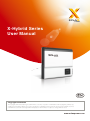
1
X-Hybrid Series
User Manual
Copyright Declaration
The copyright of this manual belongs to SolaX Power Co., Ltd. . Any corporation or individual should not plagiarize, partially copy
or fully copy it (including software, etc.), and no reproduction or distribution of it in any form or by any means. All rights reserved.
SolaX Power Co., Ltd. reserves the right of final interpretation. This information is subject to changes without notice.
www.solaxpower.com
Contents
Contents
...................................................................................
03
SCOPE OF VALIDITY ............................................................................................
TARGET GROUP ...................................................................................................
SYMBOLS USED ...................................................................................................
03
03
03
1 NOTES ON THIS MANUAL
1.1
1.2
1.3
..........................................................................................................................
04
APPROPRIATE USAGE .........................................................................................
IMPORTANT SAFETY INSTRUCTIONS ...............................................................
EXPLANATION OF SYMBOLS .............................................................................
EC DIRECTIVES .....................................................................................................
04
05
06
09
........................................................................................................
10
....................................
BASIC FEATURE AND DIFFERENT WORKING MODES
TERMINALS OF X-HYBRID READY INVERTER, HYBRID INVERTER AND BMU
DIMENSION .........................................................................................................
IDENTIFICATION OF X-HYBRID ........................................................................
10
10
12
13
2 SAFETY
2.1
2.2
2.3
2.4
3 INTRODUCTION
3.1
3.2
3.3
3.4
...............................................
13
DC INPUT .............................................................................................................
AC OUTPUT ..........................................................................................................
EPS OUTPUT WITH INTERNAL CHARGER(E VERSION FOR SK-SU) ................
EFFICIENCY, SAFETY AND PROTECTION .........................................................
INTERNAL CHARGER (FOR SK-SU)........................................................................
GENERAL DATA .....................................................................................................
13
14
14
15
15
16
...........................................................
16
5 .1 ELECTRICAL DATA ..............................................................................................
5 .2 GENERAL DATA ....................................................................................................
16
17
............................................................................................................
17
UN PACKING ........................................................................................................
CHECK FOR TRANSPORT DAMAGE ..................................................................
INSTALLATION PRECAUTION ............................................................................
PREPARATION ......................................................................................................
INSTALLATION STEPS .........................................................................................
CONNECTIONS OF X-HYBRID SYSTEM .............................................................
6.6.1 THE MAIN STEPS TO CONNECT THE X-HYBRID SYSTEM .......................
17
19
19
21
22
23
23
4 TECHNICAL DATA FOR X-HYBRID INVERTER
4 .1
4.2
4.3
4.4
4.5
4.6
5 TECHNICAL DATA FOR X-HYBRID BMU
6 INSTALLATION
6.1
6.2
6.3
6.4
6.5
6.6
01
Contents
6.6.2 COMMUNICATION INTERFACE .............................................................
6.7 INVERTER MANIPULATION
7 OPERATION METHOD
........................................................................................
34
35
36
7.1 CONTROL PANEL .................................................................................................. 36
7.2 LCD FUNCTION .................................................................................................... 37
7.3 LCD OPERATION ................................................................................................... 38
8 TROUBLESHOOTING
...........................................................................................
48
8.1 TROUBLE SHOOTING ......................................................................................... 48
8.2 ROUTINE MAINTENANCE .................................................................................. 52
9 DECOMMISSIONING
..........................................................................................
9.1 DISMANTLING THE INVERTER ..........................................................................
9.2 PACKAGING .........................................................................................................
9.3 STORAGE ..............................................................................................................
9.4 DISPOSAL .............................................................................................................
02
53
53
53
53
53
Notes on this Manual
1 Notes on This Manual
1.1 Scope of Validity
This manual is an integral part of inverter, and it describes the assembly, installation,
commissioning, maintenance and failure search of the below inverters. Please
read it carefully before operating.
SK-TL3000
SK-SU3000
SK-BMU1300
SK-TL3700
SK-SU3700
SK-BMU2500
SK-TL5000
SK-SU5000
SK-BMU5000
The X-hybrid has E version and C version.
The C version is provided with suffix”C”and is mainly for city solution,without EPS
function.All model number of the C version inverter will be provided with suffix”C”.
The E version is mainly for country solution ,with EPS function.
Store this manual where it will be accessible at all times.
1.2 Target Group
This manual is for qualified electricians. The tasks described in this manual only
can be performed by qualified electricians.
1.3 Symbols Used
The following types of safety instructions and general information appear in this
document as described below:
DANGER !
“Danger” indicates a hazardous situation which, if not avoided,
will result in death or serious injury.
WARNING!
“Warning” indicates a hazardous situation which, if not avoided,
could result in death or serious injury.
CAUTION!
“Caution” indicates a hazardous situation which, if not avoided,
could result in minor or moderate injury.
NOTE!
“Note” provides tips that are valuable for the optimal operation
of your product.
03
Safety
2 Safety
2.1 Appropriate Usage
The X-hybrid includes :
- Hybrid ready inverter SK-TL which can convert the DC current of the PV generator
into AC current for on grid or off grid usage.
- Hybrid inverter SK-SU, which can store the energy in the battery for self-use and
also can convert the DC current of the PV generator into AC current for on grid or
off grid usage.
- Hybrid battery management unit (BMU), which can work together with the
SK-TL to implement a battery storage system.
- X-hybrid E version with EPS can supply the energy from battery and PV generator
when the grid is lost.
X-Hybrid inverter(E version)
PV array
Grid
DC distribution box
Surge arrestor
Fuse
DC Breaker
EPS
Surge arrestor
Fuse
AC Breaker
*Fuse
Breaker
AC distribution box
*Battery
Current
Electric meter,
sensor﹡
bidirectional
Load
Electrical
grid
Public
Grid
L line
CT
Note: ﹡For SK-TL series , the fuse and battery are not used
﹡The CT can be replaced with meter if necessary.
﹡The EPS function is only for E version
04
EPS contactor
EPS
Load
Safety
Surge protection devices (SPDs) for PV installation
WARNING!
Over-voltage protection with surge arresters should be provided
when the PV power system installed.
The grid connected inverter is not fitted with SPDs in both PV
input side and MAINS side.
Lighting can cause damage either from direct strike or from surges due to a nearby
strike.
Induced surges are the more likely cause of lighting damage in majority or installations,
especially in rural areas where electricity is usually by long overhead lines. Surge
may be included on both the PV array conduction and the a.c. cables leading to
the building.
Specialists in lighting protection should be consulted during the end use application.
Using appropriate external lighting protection, the effect of a direct lightning
strike into a building can be mitigated in a controlled way, and the lightning
current can be discharged into the ground.
Installation of SPDs to protect the inverter against mechanical damage and
excessive stress include a surge arrester in case of a building with external
lightning protection system (LPS) when separation distance is kept.
To protect the d.c. system, surge suppression device (SPD type2) should be fitted
at the inverter end of the d.c cabling and at the array, located between the
inverter and the PV generator, if the voltage protection level (VP) of the surge
arresters is greater than 1100V, a additional SPD type 3 required for surge protection
for electrical devices.
To protect the a.c system, surge suppression devices (SPD type2) should be
fitted at the main incoming point of a.c supply (at the consumer’s cutout),
located between the inverter and the meter/distribution system; SPD (test
impulse D1) for signal line according to EN 61632-1.
All d.c cables should be installed to provide as short runs as possible, and positive
and negative cables of the same string or main d.c supply should be bundled
together. Avoiding the creation of loops in the system. This requirement for
short runs and bundling includes any associated earth/bundling conductors.
Spark gap devices are not suitable to be used in d.c circuits as once conducting,
they won’t stop conducting until the voltage across their terminals is typically
more than 30 volts.
2.2 Important Safety Instructions
DANGER!
DANGER TO LIFE DUE TO HIGH VOLTAGES IN THE INVERTER!
• All work on the inverter must be carried out by qualified electrician.
• The appliance is not to be used by children or persons with reduced
physical sensory or mental capabilities, or lack of experience and
knowledge, unless they have been given supervision or instruction.
• Children should be supervised to ensure that they do not play with
the appliance.
05
Safety
CAUTION!
DANGER OF BURN INJURIES DUE TO HOT ENCLOSURE PARTS!
During operation, the upper lid of the enclosure and the
enclosure body may become hot.
• Only touch the lower enclosure lid during operation.
CAUTION!
POSSIBLE DAMAGE TO HEALTH AS A RESULT OF THE EFFECTS
OF RADIATION!
• Do not stay closer than 20 cm to the inverter for any length of time.
NOTE!
Grounding the PV generator.
Comply with the local requirements for grounding the PV modules
and the PV generator. SolaX recommends connecting the generator
frame and other electrically conductive surfaces in a manner which
ensures continuous conduction and ground these in order to have
optimal protection of the system and persons.
2.3 Explanation of Symbols
This section gives an explanation of all the symbols shown on the inverter and
on the type label.
Symbols on the Inverter
Symbol
Explanation
Operating Display.
The battery is in charging or discharging.
Communication is active.
An error has occurred, please inform your installer immediately.
Symbols on the Type Label
Symbol
Explanation
CE mark.
The inverter complies with the requirements of the applicable CE guildlines.
06
Safety
TUV certified.
RCM remark.
SAA certification.
Beware of hot surface.
The inverter can become hot during operation. Avoid contact
duringoperation.
Danger of high voltages.
Danger to life due to high voltages in the inverter!
Danger.
Risk of electric shock!
Observe enclosed documentation.
The inverter can not be disposed of together with the household waste.
Disposal information can be found in the enclosed documentation.
Don’t work on this inverter until it is isolated from battery,mains and
on-site PV generation suppliers.
Danger to life due to high voltage.
There is residual voltage in the inverter which needs 5 min to discharge.
• Wait 5 min before you open the upper lid or the DC lid.
Important Safety Instructions
When using the product, please do remember the below information to avoid
the fire, lightning or other personal injury:
WARNING!
Ensure input DC voltage ≤Max. DC voltage . Over voltage may cause
permanent damage to inverter or other losses, which will not be
included in warranty! This chapter contains important safety and
operating instructions. Read and keep this Operation Guide for
future reference.
WARNING!
Authorized service personnel must disconnect both AC and DC
power from the X-hybrid inverter before attempting any
maintenance or cleaning or working on any circuits connected to
the X-hybrid inverter.
• Read all instructions, cautionary markings on the inverter, and all appropriate
sections of this manual before using this inverter.
07
Safety
• Use only attachments recommended or sold by SolaX.
• Make sure that existing wiring is in good condition and that wire is not undersized.
Do not operate the X-Hybrid Series inverter with damaged or substandard wiring.
• Do not disassemble the X-Hybrid Series inverter. It contains no user-serviceable
parts. See Warranty for instructions on obtaining service. Attempting to service
the X-Hybrid Series inverter yourself may result in a risk of electric shock or fire
and will void your warranty.
• Keep away from flammable, explosive materials to avoid fire disaster.
• The installation place should be away from humid or corrosive substance.
• Authorized service personnel must use insulated tools when installing or working
with this equipment.
• PV modules shall have an IEC 61730 class A rating.
PE Connection and Leakage Current
• The end-use application shall monitoring of the protective conductor by residual
current operated protective device (RCD) with rated fault current Ifn≤240mA
which automatically disconnects the device in case of a fault.
• DC differential currents are created (caused by insulation resistance and through
capacities of the PV generator). In order to prevent unwanted triggering during
operation, the rated residual current of the RCD has to be min 240mA.
The device is intended to connect to a PV generator with a capacitance limit of
approx 700nf.
WARNING!
High leakage current!
Earth connection essential before connecting supply.
• Incorrect grounding can cause physical injury, death or equipment malfunction
and increase electromagnetic.
• Make sure that grounding conductor is adequately sized as required by safety
regulations.
• Do not connect the ground terminals of the unit in series in case of a multiple
installation. This product can cause current with a d.c component, Where a residual
current operated protective (RCD) or monitoring (RCM) device is used for protection
in case of direct or indirect contact, only an RCD or RCM of type B is allowed
on the supply side of this product.
• For Australia and New Zealand:
The installation of inverter must fulfill Australia national Wiring rules AS/NZS3000,
AS/NZS4777.1 and AS/NZS5033.
WARNING!
Do not work on the inverter when the device is running.
• Never touch either the positive or negative pole of PV or battery connecting
device. And never ever touch both at the same time.
WARNING!
Risk of electric shock!
08
Safety
• The unit contains capacitors that remain charged to a potentially lethal voltage
after the MAINS , battery and PV supply has been disconnected.
• Hazardous voltage will present for up to 5 minutes after disconnection from power
supply.
• CAUTION-RISK of electric shock from energy stored in capacitor, never work on
the solar inverter couplers. The MAINS cable, Battery cable, PV cables or the PV
generator when power is applied. After switching off the PV , battery and Mains,
always wait for 5minutes to let the intermediate circuit capacitors discharge before
you unplug DC ,battery inplug and MAINS couplers.
• When access to internal circuit of solar inverter, it is very important to wait 45
minutes before working on power circuit or demounting the electrolyte capacitors
inside the device. Do not open the device before hand since the capacitors
require this long to discharge sufficiently!
• Measure the voltage between terminals UDC+ and UDC- with a multi-meter
(impedance at least 1Mohm) to ensure that the device is discharged before
beginning work (35VDC) inside the device.
2.4 EC Directives
This chapter follows the requirements of the European low voltage Directives,
which contains the safety instructions and conditions of acceptability for the
endues system, which you must follow when installing, operating and servicing
the unit. If ignored, physical injury or death may follow, or damage may occur to
the unit. Read this instructions before you work on the unit. If you are unable to
understand the dangers, warnings, cautions or instructions, contact the
manufacturer if an authorized service dealer before installing. Operating and
servicing the unit.
The X-Hybrid inverter meets the requirement stipulated in Low voltage
Directive (LVD) 2006/95/EC and Electromagnetic compatibility (EMC) Directive
2004/108/EC. The unit is tested based on:
EN 50178:1997
EN 62109-1:2010
EN 62109-2:2011
VDE 0126-1-1:2006
VDE 4105:2011
In case of installation in PV system, startup of the unit (i.e. start of designated
operation) is prohibited until it is determined that the full system meets the
requirements stipulated in EC Directive (2006/95/EC,2004/108/EC, etc.)
The X-Hybrid inverter leaves the factory completely connecting device
and ready for connection to the mains , Battery and PV supply. The unit shall be
installed in accordance with national wiring regulations. Compliance with safety
regulations depends upon installing and configuring system correctly, including
using the specified wirings. The system must be installed only by professional
assemblers who are familiar with requirements for safety and EMC. The assembly is
responsible for ensuring that the end system complies with all the relevant laws in the
country where it is to be used.
The individual subassembly of the system shall be interconnected by means of
the wiring methods outlined in national/international such as the national electric
cod (NFPA) No.70 or VDE regulation 0107.
09
Introduction
3 Introduction
3.1 Basic Feature and Different Working Modes
The X-Hybrid series including X-Hybrid ready inverter, X- Hybrid inverter and
X-Hybrid battery management unit. With all these function modules, you can
design your own PV Hybrid storage system as you needed.
The Hybrid system need to be build with either a X-Hybrid ready inverter, a battery
management unit and a battery system or a X-Hybrid inverter and a battery system.
We have the below working modes for your home made energy storage system.
• Self Use
In the “Self Use” mode the priority of the PV generated power will be : local
load> battery> public grid. It means the PV generated power will be used
in local load then the battery charging and the redundancy power will be
delivered to the public grid.
• Force Time Use
In the “Force Time Use” mode, user can set the charging and discharging time
according to his wishes and also can chose if charge from grid if allowed.
• Export control
When the user set the export control value, the inverter can limit the
energy feed in to the grid.
• EPS mode
The X-Hybrid E version integrated with EPS function. The inverter will
automatically switch to EPS output when the grid is off. User need to set the
battery remaining value for the EPS. When use the EPS function, need to fit
the load power rating with the EPS power rating.
WARNING!
• Make sure the load powering rating is within the EPS’s output
rating, Or the inverter will shutdown with an “over load “ warning .
• When an “over load” is appeared, adjust the load power make
sure it is with the rang of the EPS output, and turn the inverter
on.
• For the nonlinear load ,please pay attention to the inrush power
make sure it is within the range of the EPS output.
3.2 Terminals of X-Hybrid Ready Inverter, X-Hybrid Inverter
and BMU
X-Hybrid Inverter (SK-SU)
A
B
C D E F G
J O
TEMP
K
10
I
L
H
Introduction
X-Hybrid Ready Inverter (SK-TL)
B
A
C D E
F
G
N
BMU
K
I
M
L
Hybrid Battery Management Unit (SK-BMU)
J
J
BMU
BMU
M
MN O
MN O
H
SK-BMU1300/SK-BMU2500
Object
A
B
C
D
E
F
G
H
I
J
K
L
M
N
O
H
SK-BMU5000
Description
DC switch
DC connector area
Ethernet connector
Outside current sensor or meter port
Communication port for dry contact.
Communication port for update.
Wifi antenna connector
Battery connector
EPS output
Battery communication port
Grid output
ON/OFF button
External BMU connector
Can communication port with external BMU
Temperature port for battery
WARNING!
Only qualified electricians can operate the connection.
11
Introduction
3.3 Dimension
Dimension for SK-SU Series
151mm
591mm
700mm
Dimension for SK-TL Series
475mm
591mm
151mm
Dimension for SK-BMU Series
591mm
SK-BMU1300/SK-BMU2500
12
449mm
151mm
591mm
294mm
SK-BMU 5000
151mm
Technical Data
3.4 Identification of X-Hybrid
Model Name
Parameter
Series Number
Labels
Manufacture Info
4 Technical Data for X-Hybrid Inverter
4 .1 DC Input
Model
SK-TL(SU)3000
SK-TL(SU)3700
Max. DC input power (W)
3300
4000
SK-TL(SU)5000
5000
DC input Voltage range(V)
100-550
100-550
100-550
MPP voltage range(V)
125-530
125-530
125-530
Rated input voltage(V)
360
360
360
Start input voltage(V)
100
100
100
Max. DC input current per
input (A)
12
12/12
12/12
Max. short-circuit current
per input (A)
15
15/15
15/15
No. of MPP inputs
1
2
2
No. of strings per MPP input
1
1
1
Optional
Optional
Optional
DC Disconnection switch
13
Technical Data
4.2 AC Output
Model
SK-TL(SU)3000
SK-TL(SU)3700
SK-TL(SU)5000
Rated output power@ cosφ=1(W)
3000
3680
4600
Max. apparent AC power(VA)
3000
3680
4600
Rated grid voltage(V)
230
230
230
AC voltage range(V)
180~270
180~270
180~270
AC nominal current(A)
13
16
20
Max. output current(A)
14.4
16
22.1
40
40
50
<3%
<3%
<3%
Max. short-circuit current(A)
The harmonic factor if output
Current at AC THD voltage<2%
AC power>0.5 nominal AC power
Rated AC frequency(Hz)
50/60
50/60
50/60
44-55/55-65
44-55/55-65
44-55/55-65
Max. inverter backfeed current to
the array(mA)
500
500
500
Inrush current(A)
60
60
60
Maximum output fault current(A)
150
150
150
Maximum output overcurrent
protection(A)
25
25
25
Rated AC frequency range(Hz)
Displacement power factor,
adjustable
0.9 leadiing...0.9 lagging
Single-phase
Feed in phase
Over voltage category
III (electric supply side), II (PV side)
4.3 EPS Output With Internal Charger ( E Version for SK-SU)
Model
EPS rated power [VA]
Rated voltage (V)
Rated frequency(Hz)
Rated current (A)
EPS Peak power[VA]
Total harmonic distortion (THD)
Swtich time(s)
14
SK-SU3000
SK-SU3700
2000
230
50/60
11
1.5×Prated, 10s
<3%
<5
SK-SU5000
Technical Data
4.4 Efficiency, Safety and Protection
Model
SK-TL(SU)3000
SK-TL(SU)3700
SK-TL(SU)5000
Max. Efficiency
97.6%
97.6%
97.6%
Euro Efficiency
97.0%
97.0%
97.0%
MPPT Efficiency
99.9%
99.9%
99.9%
Over voltage/under voltage
protection
YES
YES
YES
Safety & Protection
DC isolation impedance
YES
YES
YES
Monitoring
ground fault protection
YES
YES
YES
Grid monitoring
YES
YES
YES
Ground fault current monitoring
YES
YES
YES
DC injection monitoring
YES
YES
YES
Back feed current monitoring
YES
YES
YES
Residual current detection
YES
YES
YES
Anti-islanding protection
YES
YES
YES
Over load protection
YES
YES
YES
Over heat protection
YES
YES
YES
4.5 Internal Charger ( for SK-SU)
Model
Battery type
Battery nominal voltage [V]
Battery voltage range [V]
Max. charge/discharge current [A]
Discharge depth (%)
Charging curve
Communication interfaces
SK-SU3000
SK-SU3700
SK-SU5000
Lead-acid battery/Lithium battery
48
40-60
50(adjustable)
80%(adjustable)
3-stage adaptive with maintenance
Can/RS232
Battery temperature sensor
Yes
Winter mode
Yes
15
Technical Data for X-Hybrid BMU
4.6 General Data
Model
SK-TL(SU)3000
SK-TL(SU)3700
SK-TL(SU)5000
Dimension (W/H/D) (mm)
475*591*151 (700*591*151)
Dimension of packing (W/H/D) (mm)
724*609*282 (850*724*282)
Weight (kg)
21(27.7)
Gross weight (kg)
26(35)
Cooling concept
Forced airflow
Noise emission(dB)
<40
Operating temperature range (°C)
-10~+50 (derating at 40)
Store temperature (°C)
-20~+60
Max.permissible relative humidity
(non-condensing)
95%
Pollution degree
II
<2000
Altitude (Km)
Degree of protection
IP20 (for indoor use)
Transformer-less
Topology
<7
Internal consumption (W)
LCD display
Backlight 16*4 character
Communication interface
Ethernet/Dry contact /wifi
Standard 5 years
Standard Warranty
5 Technical Data for X-Hybrid BMU
5.1 Electrical Data
Model
SK-BMU1300
Charger communication with
Battery type
Lead-acid battery/lithium battery
Battery nominal voltage [V]
48
Battery voltage range [V]
40-60
Discharge depth (%)
Charger communicate with bat.
Charging curve
16
SK-BMU5000
CAN
inverter
Max. charge/discharge current [A]
SK-BMU2500
360-460
Charger input Voltage(V)
80%(adjustable)
25
50
100
Can/RS232
3-stage adaptive with maintenance
Battery temperature sensor
Yes
Winter mode
Yes
Installation
5.2 General Data
Model
SK-BMU1300
Dimension (W/H/D) (mm)
SK-BMU2500
SK-BMU5000
592*290*140
724*409*282
Dimension of packing (W/H/D) (mm)
Weight (kg)
12
16
Gross weight (kg)
592*450*140
724*579*282
12
16
16
21
Forced airflow
Cooling concept
<40
Noise emission(dB)
-20∼+50 (derating at 40)
-20∼+60
<2000
Altitude (Km)
IP20 (for indoor use)
Degree of protection
6 Installation
6.1 Unpacking
Check the delivery for completeness. Contact your dealer at once if anything
is missing.
A
B
C
D
E
F
G
H
17
Installation
I
K
L
M
N
O
P
Q
R
S
T
Object
Quantity
A
1
X-hybrid series inverter
Description
B
1
Bracket
C
1
Warranty card
D
1
User manual
E
F
4
4
Expansion tubes
Expansion screws
G
2/4
H
2/4
I
J
1
DC connectors
2 units (1* positive ,1* negative) for SK-TL3000/SK-SU3000
4 units (2* positive ,2* negative)
DC Pin contact
2 units (1* positive ,1* negative) for SK-TL3000/SK-SU3000
4 units (2* positive ,2* negative)
AC connector
1
EPS connector(only for E-version)
K
1
Current sensor
L
1
RJ 45 extend port for current sensor
M
1
WIFI antenna
N
1
Battery connecter (for SK-SU only)
O
2
Circuit cord end terminal for battery( for SK-SU only)
P
1
1
1
Battery thermal sensor (for SK-SU only)
Q
R
S
T
18
J
1
1
1
8 pin terminal block male connector for dry connector.
Wrench tool for separate DC connector
Quick installation guide
WIFI setting guide
Installation
Open the package and pick the product, check that if there is any distortion
or impaired during the transportation. Meanwhile, check that if the relating
accessories and the materials are here, you can see the accessories list in the
table.
The instruction manual is an integral part of the unit and should therefore be
read and kept carefully.
It is recommended that the packaging should not be removed until the unit
is located in the installation site.
6.2 Check for Transport Damage
Check if the X-hybrid series inverter has some visible external damage , such
as cracks in the housing or display please contact with your dealer if you find
any damage.
6.3 Installation Precaution
The X-hybrid series inverter is designed for indoor installation (IP20)
Make sure the installation site does not fall into one of the following conditions:
•
•
•
•
•
•
•
•
•
•
•
•
Do not install the inverter in direct sunlight.
Do not install the inverter on flammable construction material.
Do not install the inverter in areas where highly flammable materials are stored.
Do not install the inverter in potentially explosive areas.
Do not install the inverter during periods of precipitation or high humidity (>95%);
Moisture trapped within the location may cause corrosion and damage to the
electric components.
Provide adequate ventilation when using batteries, and also read the warning
label on the bottom of the inverter.
Install the inverter in a location that maintains an ambient air temperature that
is less than 40°C;That is to maintain a safe internal component temperature,
the inverter would reduce power if the ambient air temperature exceeds 40°C.
The inverter should be installed in a location that is not accessible for children.
The inverter emits a slight vibrating noise when operating, which is normal
and no effect on performance.
The slope of the wall should be within ±5°.
The inverter is heavy, ensure the mounting place is strong enough to hold the
weight of the inverter.
If you install the inverter in a cabinet, closet or other small enclosed area, sufficient
air circulation must be provided in order to dissipate the heat generated by the
unit.
19
Installation
Available Space Size
WARNING !
Before installation and maintenance, AC and DC side doesn’t carry
electricity, but if DC side is just disconnected, capacitance still contains
electricity, so please wait for at least 5 minutes to ensure the capacitors
completely release the energy and inverter is not electrified.
NOTE!
Inverters should be installed by technicians.
20
Installation
6.4 Preparation
Below tools are needed before installation.
Installation Tools
Installation Tools: crimping pliers for binding post and RJ45, screwdriver, manual
wrench, ф 6 driller and rubber hammer.
Lifting and Handling
The unit is heavy. Do not lift it alone.
• During lifting procedures ensure that the unit is firmly secured to avoid the risk
of accidental tipping or dropping.
• Parts serving for support or immobilization of unit shall be designed and
manufactured so as to minimize the risk of physical injuries and of accidental
loosening of fixing.
• Ensure that the method of lifting will not allow the unit to slip from chains and
slings or turn-over or slide from lifting devices.
• Transportation must be carried by specialized person (truck operators. Hook-up
personal), equipped with the necessary protection equipments (overalls, safety
shoes, protective gloves, helmets, goggles)
• Do not walk or stand beneath or in the proximity of the load.
• Avoid sudden movements and jolts when unloading and positioning the unit.
Internal handling procedures must be conducted with care. Do not exert
leverage on the components of the machine.
• If the unit is not balanced apply ballast. Any protruding parts should not be
supported by hand.
• The inverter should be installed so that the operating panel shall be easily
accessible- easy access to the electrical power connection point.
• Accessible for maintenance and repair work.
• Parts serving for support or immobilization of unit shall be designed and
manufactured so as to minimize the risk of physical injuries and accidental
loosening of fixings.
• Loading capacity and hardness of the supporting surface, load rating of
mounting bracket should be at least four times the weight of the devices
according to IEC62109-1. and supporting characteristics will be impaired by
wear, corrosion, material fatigue or ageing, This should be calculated by
inspection of the design data of supporting material and consulting
construction engineer.
21
Installation
6.5 Installation Steps
Step1: Screw The Wall Bracket on The Wall
• Use the wall bracket as a template to mark the position of the 4 holes.
• Drill holes with ф6 driller carefully, make sure the holes are deep enough (at least
50mm) for install and tight the expansion tubes.
• Install the expansion tubes in the holes, and tight them . Install the wall bracket
using the expansion screws in the screw package.
Step2: Hang the X-hybrid Inverter On the Wall Bracket.
• Transportion of the inverter needs at least 2 people, each one needs to