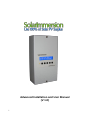
1
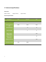
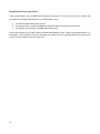
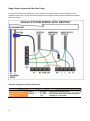
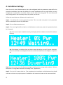
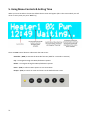
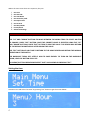
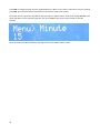
Advanced Installation and User Manual
(V 1.0)
1
Contents
1.
Overview
2.
Technical Specifications
3.
Installation
Mounting
Electrical Installation
Clamp Installation
Wiring Diagrams
4.
Installation Settings
5.
LCD Display & Menu Controls – Setting Time
2
Safety Notes
Potentially dangerous High Voltages are present and therefore this equipment
should only be installed by a qualified person.
Connect the equipment according to the correct IEE regulations and separate all
wiring according to IEC1010.
Make sure all screw terminals are tight before you switch the equipment on.
Don’t touch any circuitry after you have connected the equipment, because there
may be lethal voltages on the circuit board or connector terminals.
Equipment designed for Pollution – Degree 2 environments only. This means you
must install it in a clean, dry environment.
3
Overview
Thank you for choosing SolarImmersion.
SolarImmersion is an intelligent surplus power control system for your PV system. It diverts surplus
power which would normally be exported to the grid. When the unit is connected to an immersion
heater, it could provide free hot water from the surplus power.
SolarImmersion - Highlights:
Heats water using surplus from all sorts of micro-generation systems (wind turbines, hydro
power)
Keeps exported power as close to zero as possible by adjusting power levels to the
immersion heater.
Single sensor clip.
LCD display for easy control and management of the unit
No need to change immersion heater or the tank.
No manual intervention required to use surplus power.
Built-in override and boost timer functions to an immersion heater manually if required.
No threshold levels so less wasted power.
Built-in multifunction relay for inductive load
Supports up to 4 slave units
Internal thermal protection
1 year warranty
Multiple loads
No flickering or line noise
4
2. Technical Specifications
Dimensions
Width: 115mm
Height: 225mm
Depth: 62mm
Electrical Specifications
Description
Min
Nominal
Max
Supply Voltage (VAC)
220
240
260
Supply Frequency
(Hz)
45Hz
50Hz
55Hz
Load Current (A)
13
16
Load Size (kW)
3
4
Relay Contact
Voltage (VAC)
250
Relay Contact
Current (A)
16
Clamp Current (A)
100
PV System Size(W)
5
500
4000
3. Installation
Mounting
To keep the installation quick and easy, we recommend that SolarImmersion is installed near to the
consumer unit as most of the connections required can usually be found here.
When choosing a suitable place to install SolarImmersion, the following should be considered:
Near to the main incoming mains supply of the property
Access to the immersion heater supply cable (normally at the consumer unit)
Access to suitable supply via 16A MCB or 13A fused outlet
Ease of access and visibility of SolarImmersion LCD Screen and control buttons
Good ventilation to keep air flowing through the unit – at least 100mm around the unit.
Suitable cable access point location – through the top or bottom of the unit
Secure the SolarImmersion to the wall with the two screws or using suitable fixings for the surface
type.
Electrical Installation
ATTENTION!
Electrical connection should only be made by a qualified competent person.
Please do not attempt to do install SolarImmersion unless you hold such qualifications or are an
experienced electrician. Alterations to fixed wiring and/or opening the consumer unit may be
required – risk of death by electrocution.
Locate the most appropriate cable access point at bottom or top of the unit to make connections
to the unit according to the wiring diagram.
Loads
The proportionally controlled primary or secondary load connected should not exceed 4kW. The
load should not include digital circuits, as they may be affected by the modulated output from
the SolarImmersion
The relay terminals could be used to drive inductive or resistive load when used with the “Relay
Mode” enabled. The max load should not exceed 4kW and could have digital circuits.
6
Terminals
ATTENTION!
Make sure the wiring cables are securely connected and fully tighten with the rising clamp
terminals. Failure to do so can result in fire or the SolarImmersion unit being damaged.
Power Terminals
Terminal
Description
O/P ( Load Out)*1
Proportional output to the load, Max 4kW
L (Live) *2
Main Live 240 V input supply from 16A MCB / 13A fused outlet
N (Neutral) *2
Mains Neutral (All neutral terminals internally connected)
E (Earth) * 3
Main Earth
Relay Terminals
Terminal
Description
NO
Normally open relay terminal
COM
Common relay terminal
NC
Normally closed relay terminal
All relay terminals are volt free and max current is 16A
Sensor Terminal
Terminal
Description
CT
AC current sensor clamp terminal
CT
AC current sensor clamp terminal
Slave Communication Terminals
Terminal
Description
Slave A
Terminal for connecting slave
Slave B
Terminal for connecting slave
7
Wiring Diagrams & Software Setup
Single Heater
For simple single heater control, no relay terminal wirings are required as the secondary load / destrat pump options are not used.
The default factory settings of the SolarImmersion are optimised for a single heater configuration.
This keeps the installation simple, as the only menu setting required is setting the correct time.
The default factory settings of the switch is configured for single heater system. So no software
setting changes is required. If any settings was changed before, please do a factory reset of the
switch via the menu controls.
8
Dual Heater System
With a single heater system, the surplus will flow to the grid once the water is hot and the
thermostat cuts off. This could be avoided using a dual heater system. The secondary load / heater
2 will be turned on when the primary load/ heater 1 thermostat is cut off. This improve the
efficiency of the system.
Software Settings for dual system:
Menu Item
Secondary Load Status
Secondary Load Time
In
Secondary Load
Timeout
Secondary Load Min
Surplus
9
Displayed
Ld. Status
Ld. Timein
Ld. Timeout
Min. Surplus
Value
Enabled
0 – 255
(Minutes)
0 – 255
(Minutes)
0-3000
(Watts)
Remarks
Enable the secondary load
Time after which the loads activates
after the primary load cuts off
How long the secondary load should run
before switching back to primary load
Minimum surplus export required before
turning on the secondary load.
Example Scenario for dual system:
If the surplus load is set at 1000w and secondary load time in is set at 20 minutes, the system will
activate the seconday load (Heater 2) if all the below is true:
1. The primary load thermostat cuts off
2. The system have a surplus of 1000w at the point when the primary load cut off
3. The system still maintains a 1000W after 20 minutes
If the Load timeout is set to 60, switch will deactivate Heater 2 after 1 hour and activate heater 1. If
the heater 2 thermostat is still at cut off stage, the heater 2 will be activated after 20 minutes (Load
Time in) and the whole cycle will continue.
10
Single Heater System with De-Strat Pump
De-strat will improve the efficiency of the system by mixing the (hot and warm) water in the
hotwater tank using a pump. Both the proportional controller and the pump could work together
with this system.
Software Settings for system with de-strat:
Menu Item
De-Strat Load Status
De-Strat Pump Start
Power Level
11
Displayed
Status
Start at.
Value
Enabled
0 – 100
(%)
Remarks
Enable the secondary load
Start the de-strat pump when the load is
running at % of power.
Example Scenario for de-strat system:
If the de-strat is enabled and the system is wired accordingly, the pump will turn on to mix the
water in the tank when the load is running at the set % power level. For example, if the pump start
power level is set at 50%, the pump will be turned on when the heater 1 or primary load is running
at 50% of it’s power (approx 1500 w surplus for a 3kW load).
12
Single Heater System with Relay Mode (For Inductive Loads)
Proportional control part of the switch can drive only inductive loads. However, the switch have a
relay option to activate and deactivate any type of loads. The relay could be programmed to turn
on the load when the surplus reaches a set level. When the surplus falls below the set point, the
relay will be de-activated and the load will turn off. The relay mode could be used together with
the proportional load.
Software Settings for system with relay mode:
Menu Item
Relay Mode Status
Relay Turn on Point
13
Displayed
Status
Start at.
Value
Enabled
50 – 4000
(Watts)
Remarks
Enable the secondary load
How much surplus before turning on the
load.
Example Scenario for de-strat system:
If the relay mode is enabled and the turn on point is set at 1500, the relay will be activated once
the export surplus reaches 1500W.
Sensor Clip Installation
The correct installation and positioning of the current sensor clip is very important for the efficient
operation of SolarImmersion. Installing the sensor wrong could result in importing of power and
user incurring additional costs for electricity.
The sensor clip should be installed at the main incoming grid supply to the building which could be
from the utility meter. (Please note - it is Utility meter NOT the PV generation meter). Close the clip
around either of the cables (Live or Neutral) from the meter. This can either be done at the meter
or inside the consumer unit. (Only open a consumer unit if you are qualified to do so or are an
experienced electrician).
If there is more than one consumer unit, the clip must be positioned at the primary income source
– before it splits.
IMPORTANT
SENSOR CLIP HAS TO BE ON THE UTLITY METER TAILS AND ALWAYS ENSURE THE CLIP IS CLOSED
SECURELY AROUND THE CABLE!
Connect the clamp wire to the terminals inside SolarImmersion. If the sensor clip cable is not long
enough it can be extended up to 50m but this must be done using a twisted pair cable in order to
stop any possible interference. Try to keep the extension cable as short as possible, as the signal
strength from the sensor is very low.
14
4. Installation Settings
Once the unit is wired, SolarImmersion has to be configured with the parameters required for the
particular installation type used. By default, for simple installations with a single heater, the only
configuration requirements are below. Please see the advanced setup guide for more advanced
setup configurations like secondary load, relay mode, de-strat etc.
Follow the steps below to calibrate and setup the unit.
Step 1: Turn off the PV or micro generation system. This is to make sure power is only imported,
which is essential for sensor clip calibration.
Step 2: Turn on SolarImmersion unit.
Step 3: Turn on a high load like a kettle or a 2kW heater to make sure power is imported and wait
for 5 seconds.
3a: If the sensor clip is installed correctly, the display will be as below with the LED indicator
blinking:
3b: If the display is as below, then you have to swap the wiring on the CT sensor terminals.
Once the terminals are swapped, restart the switch and make sure the display is as picture
3a.
Step 4: Set the correct time & software settings according to the wiring mode selected. (Please
see section 5. Using Menu Controls and Setting Time / Appendix 1)
Step 5: Turn the PV inverter back on. That completes the installation and SolarImmersion should
now start to divert any surplus power if available to the immersion heater or the connected load.
15
5. Using Menu Controls & Setting Time
When you have turned on the unit the default home screen will appear (this is the screen which you will
return to every time you press “ESC” key)
There are FIVE control buttons underneath the LCD screen:
Override – (OVR) to activate the Override function (Hold for 2 seconds to activate)
Up – to navigate through the Menu/Sub Menu options
Down – to navigate through the Menu/Sub Menu options
Enter – (ENT) to select a Menu option or save new values
Escape – (ESC) to cancel an action and return to the default home screen
16
Within the main menu there are 9 options, they are:
1
2
3
4
5
6
7
8
9
Set Time
Set Override
Set Auto Boost
Set Secondary Load
Set Export Level
Set De-Strat
Set Relay Mode
Factory Reset
Advanced Settings
IMPORTANT
TO ACTIVATE THE MAIN MENU, HOLD DOWN THE “ENT” BUTTON FOR 4 SECONDS.
USE “UP” AND “DOWN” BUTTONS TO MOVE BETWEEN THE MENU ITEMS. TO SELECT AN ITEM
TO CHANGE, PRESS “ENT” BUTTON. ONCE THE CORRECT VALUE IS SELECTED USING THE “UP”
AND “DOWN” BUTTONS, PRESS “ENT” BUTTON TO SAVE THE VALUE. THE SCREEN WILL RETURN
TO THE DEFAULT HOME DISPLAY AFTER SAVING THE VALUE.
USE “ESC” BUTTON AT ANY TIME TO RETURN TO THE HOME SCREEN AND RETAIN THE NORMAL
OPERATION OF THE SWITCH
LCD BACKLIGHT TURNs OFF AFTER 5 MIN TO SAVE ENERGY. TO TURN ON THE BACKLIGHT
AGAIN, HOLD ESC BUTTON FOR 1 SEC.
ALL MENU/ BUTTON OPERATIONS EXCEPT “OVR” SHOULD END BY PRESSING “ESC”.
Setting the time
Activate menu and select “Set time” by pressing “Ent” button to get the screen below:
17
Press ENT to change the hour and use Up/Down buttons. When correct hour is selected to save the settings
press ENT. The new value will be saved and you will return to the home screen.
To set the minute, repeat the step above until you come to “Menu>Hour” scroll up to change minute, press
enter and select correct minutes using the “UP” and “DOWN” keys. Press “ENT” button to save the
minutes.
Once this action has been carried out you will return to the Default home screen.
18
Appendix – 1
Menu Options & Controls – Full List
Setting the time
Activate menu and select “Set time” by pressing “Ent” button to get the screen below:
Press ENT to change the hour and use Up/Down buttons. When correct hour is selected to save the settings
press ENT. The new value will be saved and you will return to the home screen.
To set the minute, repeat the step above until you come to “Menu>Hour” scroll up to change minute, press
enter and select correct minutes using the “UP” and “DOWN” keys. Press “ENT” button to save the
minutes.
Once this action has been carried out you will return to the Default home screen.
Setting the override function
The override function can be activated to bypass the Solarimmersion switch and turn on the immersion
heater. For example, if there is a boiler failure and you need to use the immersion heater to heat water.
19
Scroll through the main menu to “Set Override”, press ENT.
There is one sub menu within the function, “Timeout”. The number below “Menu>Timeout” is the number
of minutes the override function will be on for.
To change this press “ENT” button and you will see “Change Timeout”. Use the Up/Down buttons to change
the minutes and press “ENT” button to save the time.
To activate the override, press the “OVR” button on the front panel whenever needed.
Setting the auto-boost function
The Auto-boost function is activated to utilize Economy7 Tariff from your energy supplier.
Scroll to “Set Auto-Boost” and press “ENT” button. The screen will tell you the status of the Auto-Boost
function.
To change the status, press ENT and change to Enabled / Disabled.
20
Scroll to “Timeout” and press ENT.
You will see “Change Timeout” with a number below. This is the number of hours you want the Auto-boost
to run for. Select the desired amount of hours and press “ENT” for Solarimmersion to save your new values.
The next submenu of the Auto-boost function is “Menu> Start Hour”. These settings will decide at what
hour the Auto-boost function should start.
To select this press enter, choose your desired start time and press “ENT” again. Your new values will be
saved and you will return to the default home screen.
Setting the secondary load
Once your immersion heater or primary load is saturated (when the water reaches the cutoff temperature
of the thermostat), the surplus power will flow back to the grid. To avoid this, you can enable a secondary
load to be activated to divert the surplus power after the primary load is cut off.
Scroll through the menu to the “Set Secondary Ld.” Option and press “ENT”. The screen will display the
status of the secondary load. To enable the Secondary Load, change the staus from “Disabled” to “Enabled”
21
Scroll to “Load Timein.” This is to set how long (minutes) after the primary load is turned off the secondary
load will activate. Press enter to change the duration.
When you have selected desired time press “ENT” to save the value.
The next sub menu is “Timeout”. Timeout decides how much time (minutes) the secondary load should
remain activated before switching back to the primary load. Please note that if the primary load is still
saturated, the whole cycle will continue and the secondary load will be turned back on.
The last sub menu is the minimum surplus. This is how much surplus power is required before the
secondary load is activated (Watts). For example, if you set the min surplus to 1000 Watts, the secondary
load will not be activated if the surplus is less than 1000Watts.
Setting the Export Level
This will set the amount of power you wish to export back to the grid, which can be as little as 0W.
22
Scroll to “Set Export Level” in the main menu and press enter. “Menu>Export Lev” will appear. Press enter
to change, select the correct amount (in multiples of ten) and press enter to save new values.
Setting the De-Strat
De-Strat will improve the efficiency of the system by enabling a pump to mix the water in the hot water
tank.
Scroll to “Set De-Strat” and press enter to see the status of this function.
The only Sub Menu in this section is the point at which the De-Strat function will activate. This is a
percentage value.
“Start at 50” means your De-Strat pump will activate when the immersion heater is working at 50% of it
capacity. For example, if you have a 3kW immersion heater the De-Strat will activate at 1500W with a
setting of 50%.
23
Setting the Relay Mode
This mode is to be used with inductive appliances.
Scroll to “Set Relay Mode” on the main menu and press “ENT”. “Menu>On Level” will be displayed. This
sets the amount of surplus power at which the load will be activated.
The number below is the amount of watts at which the load will activate. To change press “ENT”and use
up/down buttons to alter wattage. Press “ENT” to save value.
Factory Reset
This function returns all settings on the switch to default settings:
24
Scroll to “Factory Reset” on the main menu and press “ENT”.
You will be asked “To reset press enter” – press “ENT” again
You will be asked once more “Factory reset. Enter to Confirm” – Press “ENT”.
The switch will now restart with the default settings.
Advanced Settings:
Advanced settings should be used only by the service personnel. Change the settings may damage the
switch.
Advanced settings menu includes:
o Cut off Temperature – Set the cut off temperature – Also displays the current system
temperature
o Temp Timeout – Timeout in minutes – How long the system should remain turned off on
over-heating situation
o Load Calibration - Connected Load – Connected load rating
o Voltage Calibration
o Current Calibration
o Phase Calibration
o Trigger Start Point – To calibrate the offset of 0-255 from microcontroller & 2-10 v of the
proportional controller.
o Display Offset – To adjust the wattage display settings on the home screen. If the settings
are less than 1000, the displayed value is reduced by the entered value. If the settings is
more than 1000, (1000-the saved value) is added to the displayed watts.
25