1
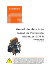
Service Manual
Proportioning Unit
evolution G-30 H
Issue 2.3 16/09/14
Ref. NR-00040-ENG
Before installing the unit and starting it up, carefully read all the technical
and safety documentation included in this manual. Pay special attention
to the information to know and understand the operation and the
conditions of use of the unit. All of the information is aimed at enhancing
User Safety and avoiding possible breakdowns derived from the incorrect
use of the unit.
evolution G-30 H
Service Manual
WARRANTY
GARRAF MAQUINARIA, S. A. (hereinafter “GAMA”) provides this LIMITED WARRANTY (hereinafter “Warranty”) to the
original purchaser (hereinafter “Customer”) covering this equipment and the original GAMA manufactured accessories
delivered with the equipment (hereinafter “Product”) against defects in material or workmanship of the Product
(hereinafter “Defect” or “Defective”) for a period of two (2) years from the date of first purchase as shown on the original
GAMA invoice (hereinafter “Warranty Period”).
If during the Warranty Period under normal use, the Product is suspected by Customer to be Defective in material or
workmanship, it is Customer’s responsibility to contact GAMA and return the Product to GAMA as directed by GAMA,
freight prepaid. If GAMA determines that the Product is Defective and that such Defect is covered by this Warranty,
GAMA will credit Customer for the reasonable freight charges incurred by Customer in returning the Defective Product
to GAMA, and GAMA (or its authorized agent) will, at GAMA’s option, repair or replace the Product, subject to the
following:
Original Invoice: The original invoice must be kept as proof of the date of first sale and the Product serial number. The
Warranty does not cover any Product if the Original Invoice appears to have been modified or altered, or when the serial
number on the Product appears to have been altered or defaced.
Product Maintenance: It is the Customer’s responsibility to maintain the Product properly. See your maintenance
schedule and owner’s manual for details. The Warranty does not cover an improperly maintained Product.
Non-GAMA Components and Accessories: Non-GAMA manufactured components and accessories that are used in the
operation of the Product are not covered by this Warranty. Such components and accessories shall be subject to the
warranty offered to the Customer, if any, by the original manufacturer of such component or accessory.
Other Warranty Exclusions: The Warranty does not cover any Product that GAMA determines has been damaged or
fails to operate properly due to misuse, negligence, abuse, carelessness, neglect, or accident. By way of example only,
this includes:
Normal wear an tear.
Improper or unauthorized installation, repair, alteration, adjustment or modification of the Product.
Use of heating devices, pumping equipment, dispensers, or other parts or accessories with the Product that
have not been approved or manufactured by GAMA.
Failure to follow the operating instructions and recommendations provided by GAMA.
Cosmetic damage.
Fire, flood, “acts of God,” or other contingencies beyond the control of GAMA.
THE WARRANTY DESCRIBED HEREIN IS THE EXCLUSIVE REMEDY FOR THE CUSTOMER AND IS IN LIEU OF ALL OTHER
WARRANTIES, EXPRESS, IMPLIED, STATUTORY OR OTHERWISE, AND THE IMPLIED WARRANTIES OF MERCHANTABILITY
AND FITNESS FOR A PARTICULAR PURPOSE AND ALL OTHER WARRANTIES ARE HEREBY DISCLAIMED. TO THE FULLEST
EXTENT PERMITTED BY LAW, GAMA SHALL NOT BE RESPONSIBLE, WHETHER BASED IN CONTRACT, TORT (INCLUDING,
WITHOUT LIMITATION, NEGLIGENCE), WARRANTY OR ANY OTHER LEGAL OR EQUITABLE GROUNDS, FOR ANY
CONSEQUENTIAL, INDIRECT, INCIDENTAL, LOST PROFITS, SPECIAL, PUNITIVE OR EXEMPLARY DAMAGES, WHETHER TO
PERSON OR PROPERTY, ARISING FROM OR RELATING TO THE PRODUCT, EVEN IF GAMA HAS BEEN ADVISED OF THE
POSSIBILITY OF SUCH LOSSES OR DAMAGES.
Non-Warranty Service by GAMA: If GAMA determines that the suspected Defect of the Product is not covered by this
Warranty, disposition of the Product will be made pursuant to the terms and conditions of GAMA’s written estimate on a
time and materials basis.
Continuing Warranty for Products Repaired or Replaced under Warranty: Following the repair or replacement of a
Product covered by this Warranty, such Product will continue to be subject to the original Warranty for the remainder of
original Warranty Period or for three (3) months from the repair or replacement date, whichever is longer.
No Rights Implied: Nothing in the sale, lease or rental of any Product by GAMA shall be construed to grant any right,
interest or license in or under any patent, trademark, copyright, trade secret or other proprietary right or material owned
by anyone; nor does GAMA encourage the infringement of same.
Exclusive Warranty: This writing is the final, complete, and exclusive expression of the Warranty covering the Product.
Any statements made by GAMA, its employees or agents that differ from the terms of this Warranty shall have no effect.
It is expressly understood that Customer’s acceptance of this Warranty, by performance or otherwise, is upon and
subject solely to the terms and conditions hereof, and any additional or different terms and conditions proposed or
expressed by Customer or anyone, whether in writing or otherwise, are null and void unless specifically agreed to in
writing by an Officer of GAMA.
2/42
Issue 2.3
http://www.gamapur.com
Ref. NR-00040-ENG
evolution G-30 H
Service Manual
All information provided in this Service Manual is assumed to be correct; although this does not
constitute any implicit or explicit liability or guarantee. GAMA reserves the right at any time and
without prior warning to make all improvements and modifications necessary to this Service
Manual, in order to rectify any possible typographical errors, supplement the information
contained or insert changes predicated by the performance or use of the unit.
SAFETY AND HANDLING
The evolution G-30 H series metering unit has been designed and manufactured in full
compliance to the provisions of Machine Directive 89/392/CEE in its modified form and the
National Regulations that transpose it. It also meets all European Directives concerning
electromagnetic compatibility and electrical safety and the provisions of the Harmonised Norms
that are applicable.
This chapter contains information on the safety, handling and use of the evolution G-30 H
series metering unit.
Before installing the unit and starting it up, carefully read all the technical
and safety documentation included in this manual. Pay special attention
to the information to know and understand the operation and the
conditions of use of the unit. All of the information is aimed at enhancing
User Safety and avoiding possible breakdowns derived from the incorrect
use of the unit.
WARNING! establishes information to alert on a situation that might cause serious
injuries if the instructions are not followed.
PRECAUTION! establishes information that indicates how to avoid damage to the unit
or how to avoid a situation that could cause minor injuries.
NB: is relevant information on a procedure being carried out.
Careful study of this manual will enable the operator to know the characteristics of the unit and
the operating procedures. By following the instructions and recommendations contained herein,
you will reduce the potential risk of accidents in the installation, use or maintenance of the unit;
you will provide a better opportunity for incident-free operation for a longer time, greater output
and the possibility of detecting and resolving problems fast and simply.
Keep this Service Manual for future consultation of useful information at all times. If you lose
this manual, ask for a new copy from your GAMA local distributor or directly contact Garraf
Maquinaria, S.A.
WARNING! The design of the evolution G-30 H series metering unit does not allow its
use in potentially explosive atmospheres or to exceed the pressure and temperature
limits described in the technical specifications of this manual.
3/42
Issue 2.3
http://www.gamapur.com
Ref. NR-00040-ENG
evolution G-30 H
Service Manual
When working with the unit, it is recommended that the operator wear suitable clothing and
elements of personal protection, including, without limitation, gloves, protective goggles, safety
footwear and face masks. Use breathing equipment when working with the machine in
enclosed spaces or in areas with insufficient ventilation. The introduction and follow-up of
safety measures must not be limited to those described in this manual. Before starting up the
machine, a comprehensive analysis must be made of the risks derived from the products to be
dispensed, the type of application and the working environment
To prevent all possible bodily harm caused by incorrect handling of the
raw materials and solvents used in the process, carefully read the safety
information provided by your supplier.
Deal with the waste caused according to current regulations.
Disconnect the unit from the power supply before carrying out any
operation inside the electrical console.
The electrical maintenance of the machine must only be performed by a
qualified electrician.
To avoid damage caused by the impact of pressurized fluids, do not open
any connection or perform maintenance work on components subject to
pressure until the pressure has been completely eliminated.
Use suitable protection when operating, maintaining or remaining in the
operating area of the unit. This includes, but is not limited to, the use of
masks, protective goggles, gloves, shoes and safety clothing.
The unit includes components that reach temperatures that are liable to
cause burns. The hot parts of the unit must not be handled until they
have cooled.
To prevent serious harm by crushing or loss of limbs, do not work with
the unit without the safety guards installed on all moving parts. Make
sure that all of the safety protections are correctly reinstalled after all
repair or maintenance work is completed.
4/42
Issue 2.3
http://www.gamapur.com
Ref. NR-00040-ENG
evolution G-30 H
Service Manual
CHARACTERISTICS
The evolution G-30 H metering unit has been designed and built for the application of
Polyureas, chemical systems for polyurethane foaming and some two-component epoxy
systems.
Principal Heating System
Consists of two independent heaters without seals. Each heater has four 1500 W heating
elements, that give the unit a total power of 6000 W, and the necessary control and safety
components for precise operation of the system. Its singular configuration allows a temperature
differential (ΔT) of 90º F and application temperatures of up to 194º F under normal conditions
of ambient temperature.
Hose Heating System
Designed with a 3000 W isolation transformer that
enables effective heating up to a total hose length of
310 feet. The system includes an innovative hose
heating concept in which the copper heating element is
spread evenly around the circumference of the hose,
providing a uniform heating watt density and precise
control of the product application temperature. This
hose heating element design is extremely resistant to
fatigue failure.
100% circumferential coverage produces the most homogenous distribution of heat available.
Double Acting Opposed Piston Metering Pumps
A pump line driven by a double rod hydraulic cylinder. The in line pump system with opposed
piston pumps provides a constant volume and guarantees uniform pressures in both directions
of pump movement. Different sized pumps allow for various volumetric ratios to be achieved
(1:4 to 4:1) between the chemical components used in the process.
5/42
Issue 2.3
http://www.gamapur.com
Ref. NR-00040-ENG
evolution G-30 H
Service Manual
TECHNICAL SPECIFICATIONS
Electrical
Main voltage: ______________________________________________________ 230 V / 400 V
Frequency: ____________________________________________________________ 50/60 Hz
Electrical consumption: ________________________ 63.1 A @ 3 x 230 V / 36.3 A @ 3 x 400 V
Pre Heater power: _______________________________________________ (2 x 6 kW) 12 kW
Hose Transformer Power: ___________________________________________________ 3 kW
Electrical Motor Power: _____________________________________________________ 3 kW
Total Active Power: _______________________________________________________ 18 kW
Inside the console, there is a terminal strip for connecting the main power
(wire not supplied) to the unit. The electrical connection of the unit must
only be carried out by a qualified electrician.
Mechanical
Maximum working pressure (with pumps 1.2): ____________ 140 kgf/cm2 (13.7 MPa) / 2000 psi
Maximum working pressure (with pumps 0.8): ___________ 240 kgf/cm2 (23.5 MPa) / 3500 psi
Maximum production ratio 1:1 (with pumps 1.2): ______________________ 11 kg/min / 24lb/min
Maximum production ratio 1:1 (with pumps 0.8): ______________________ 7 kg/min / 15 lb/min
Minimum production: ___________________________________________ 1 kg/min / 2,2 lb/min
Maximum hose length: _________________________________________________ 93 m/310 ft
Recommended compressor: _________________________________________ 3 HP III phase
Approximate weight (hydraulic tank empty): ____________________________ 160 kg / 352 lbs
Approximate weight (hydraulic tank full): _______________________________ 240 kg / 528 lbs
Dimensions: ___________________________________________________ H: 1200 mm / 48 in
W: 900 mm / 35 in
L: 700 mm / 28 in
6/42
Issue 2.3
http://www.gamapur.com
Ref. NR-00040-ENG
evolution G-30 H
Service Manual
GENERAL DESCRIPTION
Figure 1. General
7/42
Description.
Issue 2.3
http://www.gamapur.com
Ref. NR-00040-ENG
evolution G-30 H
Service Manual
1. Control Panel
Controls and regulates the operation of the unit.
2. Isocyanate Metering Pump
Meters the Isocyanate.
3. Polyol Metering Pump
Meters the Polyol.
4. Isocyanate Pre Heater
Heats the Isocyanate to the pre-set temperature.
5. Polyol Pre Heater
Heats the Polyol to the pre-set temperature.
6. Hose Heating Transformer
Supplies the required voltage for heating the hoses.
7. Hydraulic Pressure Gage
Indicates the pressure in the hydraulic drive system.
8. Isocyanate Pressure Gage
Indicates the pressure in the Isocyanate system.
9. Isocyanate Safety Pressure Switch
Deactivates the directional valve in the event of excessive pressure in the Isocyanate system.
10. Isocyanate Temperature probe
Provides information on the temperature of the Isocyanate.
11. Polyol Pressure Gage
Indicates the pressure in the Polyol system.
12. Polyol Safety Pressure Switch
Deactivates the directional valve in the event of excessive pressure in the Polyol system.
13. Polyol Temperature Probe
Provides information on the temperature of the Polyol.
14. Recirculation Kit
15. Hydraulic Pressure Regulator
Allows the pressure of the hydraulic system to be increased
or decreased. Turn clockwise to increase the pressure and
counterclockwise to reduce it. In order to regulate the
pressure of the hydraulic system, the NORMAL or
RETRACT key must be activated.
The regulation mechanism has two configurations:
a) Limiting of pressure with pin, for low pressure
hoses (up to 155 bar).
b) Limiting of pressure without pin, for high pressure
hoses (up to 276 bar).
Regulate the hydraulic system so that the output pressure of the unit
never exceeds the pressure of work of the installed product hoses.
8/42
Issue 2.3
http://www.gamapur.com
Ref. NR-00040-ENG
evolution G-30 H
Service Manual
16. DIP S1 Selector TPC Probes
This sets the hose heating control mode
to be selected, depending on whether
the
system
includes
a
single
Temperature Control Sensor (TCS) for
automatic temperature control or no
TCS for manual temperature control.
Please
be
aware
that
after
manipulating the DIP selector you
should switch off the unit so the
change. (in detected buy the board).
17. DIP S2 Selector Control Units
This sets the pressure and temperature
units that will be shown on the control
panel displays to Metric or English. Set
to EU for the pressure to be shown in
bar and the temperature to be shown in
degrees Celsius. Set to USA for the
pressure to be shown in psi and the
temperature to be shown in degrees
Fahrenheit. Please be aware that after
manipulating the DIP selector you
should switch off the unit so the
change. (in detected buy the board).
18. DIP S3 selector – Input Voltage selector
It allows selecting the input voltage. Moving the 1 switch to ON for 230V with neutral and to OFF
for 400V without neutral. Selection is factory set and cannot be modified without GAMA
technical service authorization. Please be aware that after manipulating the DIP selector
you should switch off the unit so the change (in detected buy the board).
9/42
Issue 2.3
http://www.gamapur.com
Ref. NR-00040-ENG
evolution G-30 H
Service Manual
CONTROL PANEL
Figure 2.
Control Panel
The Control Panel allows the optimum working conditions to be selected and set, depending on
the characteristics and requirements of the products to be dispensed. Using the MODE key, the
different control parameters may be entered. The parameter display will flash for a few seconds
to allow the change of this value by pressing the UP / DOWN keys. Once the change is made,
press the MODE key once more for the new value to be entered into memory and to select the
next parameter for setting.
The modification mode will be interrupted automatically after 3 seconds without activity on the
keyboard.
The parameters that may be selected and displayed are the following:
Hose temperature in automatic control mode (maximum 90º C / 194 F)
Hose heating power (maximum 50 Amps)
Isocyanate heater temperature (maximum 90ºC / 194 F)
Polyol heater temperature (maximum 90ºC / 194 F)
Total number of cycles to be made
Number of cycles made
10/42
Issue 2.3
http://www.gamapur.com
Ref. NR-00040-ENG
evolution G-30 H
Service Manual
1. Main Power Switch
Turns the electric supply to the control panel on and off. It must be turned ON for any operation
to be performed with the unit. When turned ON, the green pilot at the top of the switch will come
on.
2. Hoses
The display shows the temperature of the Isocyanate hose
(ISO) and the temperature of the Polyol hose (RESIN).
The hose heating control may be automatic (optional) if using
a Temperature Control Sensor (TCS) or manual. The control
mode must be established with the two DIP selectors on the printed circuit board (S1).
If the TCS is located in the ISO hose (the recommended placement), then set the Isocyanate
DIP selector to ON and the Polyol DIP selector to OFF. In this setup, the Isocyanate
temperature will show on the indicator and the Polyol indicator will be blank. If the hose heat
system does not include a TCS or the sensor is inoperative, then set both DIP selectors to OFF.
In this setup, both temperature indicators will be blank. In the units equipped with two hose
transformer power, locate the DIP “Hose ISO” and the DIP “Hose RESIN” to ON position if the
hoses have TCS for the temperature control system, or OFF position if the hoses not have
TCS.
Please be aware that after manipulating the DIP selector you should switch off the unit so
the change. (in detected buy the board).
ISO on / RESIN off
w/TCS
ISO off / RESIN off
manual control
Dual Hose Heat
(optional)
To select the temperature when the unit is working in automatic control mode, press the MODE
key until the temperature flashes, select the required temperature by pressing the UP/DOWN
keys and press the MODE key once more to enter the selected value into memory. Repeat the
process to select the Amps. When the unit is in automatic mode, the value of the power must
be set between 45 and 50 Amps.
Hose temperature settings that are higher than the temperature settings of the heaters cannot
be programmed.
If only one temperature control system is working (ISO or POL), the limiting temperature value
will be the highest set in the heaters.
If both temperature control systems are working (ISO and POL), the limiting value will be related
to each of their corresponding heaters.
Temperature settings are restricted to 80ºC maximum for hoses and 90ºC maximum for
heaters.
11/42
Issue 2.3
http://www.gamapur.com
Ref. NR-00040-ENG
evolution G-30 H
Service Manual
For the data input, the order will be as follows:
Temperature set-point for A(ISO) heater and B or R (POL).
Temperature set-point for A(ISO) hose and B or R (POL).
Amps set-point for A (ISO) and B or R (POL).
Set-point for the MAXIMUM and MINIMUM pressure for A (ISO).
Set-point for the MAXIMUM and MINIMUM pressure for B or R (POL).
Ratio pressure adjustment.
Cycles pre-selection.
Date input
N.B.: When the MAXIMUM pressure is set, all the upper horizontal segments for all the
digits in the counter display will be enlightened. Likewise for the lower segments when
the MINIMUM pressure is set
If the TCS stops working, the temperature display will show the symbol (---) and the heating will
be automatically turned off.
AT start-up, the hose heat set point is not maintained in memory and must be reset after each
activation of the CONTROL POWER key.
To select the hose power when the unit is working in manual heating control mode, press the
MODE key until the amperage flashes, press the UP / DOWN keys to enter the number of amps
required and press the MODE key once more to enter the value into memory.
Refer to the table shown below to select the power that is required to reach the application
temperature:
30 A
35 A
40 A
45 A
50 A
38º C
48º C
60º C
75º C
90º C
100º F
118º F
140º F
167º F
194º F
Select the required amps for a quick pre-heating.
N.B.:
The circuit breaker software of the transformer has a safety system to prevent the hoses
from being exposed to high temperatures during long periods of time.
If you have selected a potential over 35 amperes, after 20 minutes, the potential will
automatically regulate to 35 amperes.
This potential cannot be set above 35 amperes until the heater is disconnected from the
hoses and reconnected.
The settings programmed by the machine operator will be stored for the next time the
heating is switched on.
12/42
Issue 2.3
http://www.gamapur.com
Ref. NR-00040-ENG
evolution G-30 H
Service Manual
3. Heaters
The display shows the temperature in the Isocyanate heater (ISO) and the temperature in the
Polyol heater (RESIN). To enter new temperature values, press the MODE key until the
respective temperature flashes; select the required temperature by pressing the UP/DOWN
keys and press the MODE key to enter the value into memory.
The pushbuttons turn on or off the heater of each product. Each pushbutton has a led that lights
steady when the heater is on; if the led flashes, it indicates that the heater is at the preset
temperature.
If the temperature control probe stops working, the temperature display will show the symbol
(---) and the heater will automatically be turned off.
AT start-up, the heater set point is not maintained in memory and must be reset after each
activation of the CONTROL POWER key.
4. Mode Key
Allows access to change the different control parameters.
5. Up / Down Keys
Allows the value of each of the parameters to be increased or decreased.
6. Pressure
Indicator displays the Isocyanate pressure (ISO) and the Polyol (RESIN)
Using the DIP S2 selector labeled USA and EU, the units of
pressure and temperature can be set. Set the switch 1 of DIP
S2 selector to EU (ON) for the pressure to be displayed in bar
and the temperature in degrees Celsius; set the switch 1 of DIP
S2 selector to USA (OFF) for the pressure to be displayed in psi and the temperature in
degrees Fahrenheit. Please be aware that after manipulating the DIP selector you should
switch off the unit so the change. (in detected buy the board).
Control method for activating/deactivating the directional valve according to the preselected
pressure:
FUNCTIONING: It is allowed to set two pressure values (MAXIMUM VALUE AND
MINIMUM VALUE) for every product, causing the directional valve deactivation when
one of the two products reaches the MAXIMUM set-point and the activation when the
same product reaches the MINIMUM set-point.
CONDITIONS FOR THE FUNCTIONING: A MAXIMUM and MINIMUM set-point has to
be set for the A product (isocyanate) and likewise for the product B or R (polyol – resin),
and the values can be different from A to B (or R).
This function will be activated when NORMAL or RETRACT is activated.
It only will be displayed, adjusted and activated if the switch 2 of the DIP S2 selector
(PRESSURE) is in ON position.
In case the MAXIMUM set-point for product A is set at 275 bar or the MINIMUM at 0
bar, the pressure control system for product A will be deactivated.
Likewise for the product B or R.
7. Counter
Indicator displays the cycles used and the cycles remaining from the preset. The cycle counter
is incremental and may be reset by simultaneously pressing the UP / DOWN keys.
13/42
Issue 2.3
http://www.gamapur.com
Ref. NR-00040-ENG
evolution G-30 H
Service Manual
The system allows pre-selecting the required number of working cycles so that the unit will
automatically stop when it reaches this number. To enter the number of cycles to reach
automatic shutdown, press the MODE key until the cycle meter flashes, select the number of
cycles with the UP / DOWN keys and press the MODE key to enter the value into memory.
When the unit starts, the cycles used will be deducted from the pre-selected cycles until the
total number of cycles requested is completed. Once completed, the display will show zero and
the unit will automatically stop.
The cycle meter display will alternate every two or three seconds to show the cycles used
(totalizer) and the cycles remaining (pre-set). The cycles remaining will be shown by the
Minus sign (-XXXXX). The counter display will also show any alarm warnings resulting from
faults.
8. Power Control Key
Pushbutton turns on and off the control voltage to the electrical circuit of the heaters and hoses.
When the key is on, the led in its center will come on. It may be turned off at will by pressing the
key once more, or automatically if an alarm is caused due to excessive temperature in the
heaters (alarms 6 and 7) or due to excessive current in the heating system of the hoses (alarm
9).
9. Motor Key
Pushbutton turns on and off the hydraulic motor. When the key is active, the led in its centre will
come on. This may be turned off at will by pressing the key once more, or automatically in the
event of overload in the hydraulic motor (alarm 8).
10. Ratio Key
Controls that the pressure difference between the two components will not be higher than the
programmed (between a 5 and a 25%), if the difference is greater than, the alarm number 10
will be activated. The system to monitor the pressure differential is activated five seconds after
pressing the NORMAL key and allows the differential to be exceeded for two seconds before
the alarm is set off. The ratio control parameters are factory set. When the key is active, the led
in its center will come on.
11. Normal Key
Activates the normal operation of the machine. When the key is active, the led in its center will
come on.
12. Retract Key
Sets the piston rod of the Isocyanate metering pump to the retract position and prevents the
crystallization of Isocyanate on the piston rod. Press the RETRACT key every time the unit is
stopped by the operator. When the key is active, the led in its center will come on.
13. Direction Indicator Pilot Lights
Indicates the direction of movement of the metering pumps. If excessive pressure is caused in
the system, the pilot lights will be turned off and alarms 3 and 4 will be set off. The functions of
the NORMAL and RETRACT keys will remain active
14. USB Port
Optional connector to insert device of massive storage for capture of data.
Only installed in Units provided with Logger (optional Units).
14/42
Issue 2.3
http://www.gamapur.com
Ref. NR-00040-ENG
evolution G-30 H
Service Manual
ALARMS
When the unit has faults caused by conditions affecting its correct operation, an audible alarm
will sound and a fault number will show on the COUNTER display. The system does not allow
an alarm to be reset until the fault causing the alarm has been corrected. After resetting, the
MODE key must be pressed.
The procedures recommended to determine the possible causes activating the alarms are
indicated in the following:
1.
Maneuvering Voltage under 170 V
Check the electrical supply connections.
2.
Check the transformer thermal limit switch.
Maneuvering Voltage over 270 V
3.
Check the electrical supply connections.
Excessive ISO Pressure (deactivates the directional valve and the heating system)
Check the product pressure.
Check the number 10 led of the printed circuit: it must be lit.
4.
Check the over pressure safety switch.
Excessive POL Pressure (deactivates the directional valve and the heating system)
Check the product pressure.
Check the number 11 led of the printed circuit: it must be lit.
5.
Check the over pressure safety switch.
Excessive ISO temperature (deactivates the POWER CONTROL)
Check the heater heating system.
Check the connections of the safety thermostat and allow it to cool so that it makes an
automatic reset.
6.
Check the number 12 led of the printed circuit: it must be lit.
Excessive POL temperature (deactivates the POWER CONTROL)
Check the heater heating system.
Check the connections of the safety thermostat and allow it to cool so that it makes an
automatic reset.
7.
Check the number 13 led of the printed circuit: it must be lit.
Fault key (it only turns on when the machine is connected to the mains)
8.
Check the keyboard.
Motor fault (the motor stops)
Check the amperage draw on the hydraulic motor.
Check the electrical connection of the hydraulic motor.
9.
Check the number 15 led of the printed circuit: it must be turned off.
Fault in Hose Heating System (deactivates the POWER CONTROL)
Replace the faulty triac.
15/42
Issue 2.3
http://www.gamapur.com
Ref. NR-00040-ENG
evolution G-30 H
Service Manual
10. Fault Ratio Off Tolerance (deactivates the directional valve)
Check the product pressures.
Replace the pressure transducer if there is no reading.
Press the ratio key to cancel the function.
11. 000000 Cycle Pre-selection made (deactivates the directional valve)
Press the MODE key to reset the counter
Set the cycle selector to zero.
Disconnect the unit from the main power supply before working on the
inside of the electrical console. The electrical maintenance of the
machine must only be performed by a qualified electrician.
16/42
Issue 2.3
http://www.gamapur.com
Ref. NR-00040-ENG
evolution G-30 H
Service Manual
INSTALLATION
PRECAUTION! Use suitable protection and follow the recommendations in the safety
information provided by product suppliers when installing or working with the unit.
GAMA provides a series of tools and accessories necessary for assembling the machine. The
kit is made up of the following elements:
12” spanner, 6” spanner, universal pliers, screwdriver, allen keys, socket, oiling unit, tube of
grease, magnet holder tools, pin extractor, component manual and service manual.
Inside the console there is a terminal strip for connecting the principal
electrical wire (not supplied) to the unit. The electrical connection of the
unit must only be carried out by a qualified electrician.
NB: To ensure that the unit works correctly, the electrical supply must meet the
specifications indicated on page six of this manual and appearing on the machine
specifications plate.
Follow the recommended procedure in the indicated order to install the unit:
a) Insert the main power cable by passing it through the wire stop at the bottom of the
electrical console and connect as shown in the diagram.
Make sure the power cable is disconnected from the mains
source before connecting it to the terminal strip in the
console.
b) Load 63 liters (16.6 gal) of hydraulic fluid into the tank of
the unit. The oil must be of the characteristics and
specifications of DIN 51524 standard, sections 1 and 2
(for example. ISO VG 46).
17/42
Issue 2.3
http://www.gamapur.com
Ref. NR-00040-ENG
evolution G-30 H
Service Manual
PRECAUTION! Do not fill the tank to maximum capacity (78 Lts –
20.6 gal); make sure the amount of oil is not more than 80% of its
maximum capacity (63 Lts. – 16.6 gal). Use the visual level indicator
of temperature on the tank as a reference, because the maximum
temperature limit (80ºC – 176ºF) coincides with the advised
capacity.
c)
Check the level of the oil in the case of the hydraulic pump:
remove the plug from the top of the pump case and check that
the oil level reaches to the top of the case. Add oil if necessary
and refit the plug.
d) Fill the lube reservoir of the Isocyanate pump with DOP. It is not
necessary to prime the system.
e) Connect the hoses of the products to the outlets of the
respective heaters (the Isocyanate hose to the Isocyanate
heater and the Polyol hose to the Polyol heater).
NB: The product hoses have been identified with red (Isocyanate) and blue (Polyol),
enabling them to be rapidly distinguished. To avoid errors in connecting the coupling
connectors of the Isocyanate and Polyol hoses, the connectors are of different sizes to
make it impossible for connections to be swapped.
Figure 3. Method
of union of the Hoses
WARNING! To join the hoses together or to connect them to the heaters or the gun,
use two spanners to hold the parts to be joined (1) and a third spanner to tighten or
loosen the connecting nut (2) as shown in the illustrations in Figure 3. The connections
must be tightened to a torque of 20 Nm.
18/42
Issue 2.3
http://www.gamapur.com
Ref. NR-00040-ENG
evolution G-30 H
Service Manual
The hoses receive vacuum drying treatment and are supplied interconnected at the ends to
prevent them from absorbing moisture. Do not separate them until they are going to be installed
in the unit.
The hose connection
system includes special
terminals (fast lock) to
facilitate the electrical
connection
to
the
transformer
and
between the different
sections installed in the
unit.
The transformer offers
the option of connecting
to a 40 V output voltage
valid for a total hose
length of up to 48
meters (158 ft), or an
output voltage of 75 V,
for
hose
lengths
exceeding 48 meters
(158 ft) to 93 meters
(305 ft). Connect to one
output voltage or the
other depending on the
total
hose
length
installed. Before starting up the unit, make sure that the connection made in the factory adapts
to the total length of hose installed. If you add or eliminate sections of hose, make sure the
output voltage of the transformer to which it is connected is suitable for the resulting total length.
Otherwise, change the connection.
f) Connect the heated hoses wires to the “fast
lock” connector coming out of the hose
transformers as follow:.
a. Unscrew the Nylon Safety Plug from the
“fast lock” connector body.
b. Unscrew partially the Socket Head Set
Screw from electrical wires.
c. Insert the heated hose electrical wire
with terminals into the “fast lock”
connector body.
d. Tighten the Socket Head Set Screw of
the terminals and place the Nylon
Safety Plugs
NB: A good practice is to add some dielectric grease to the ID of the connector.
Repeat the same steps to connect the “fast lock” that you will find in the middle hose
connections
g) Connect the rest of the product hoses to complete the required length. Remember that
the hoses are identified with red (Isocyanate) and blue (Polyol).
NB: Assure the proper mechanical and electrical connection of the hoses to avoid
possible product leakage and hose heat problems.
19/42
Issue 2.3
http://www.gamapur.com
Ref. NR-00040-ENG
evolution G-30 H
Service Manual
h) Install the probe of control of temperature
TCS between the last stretch of hose of
product and the final stretch connected to
the gun. Stretch carefully the cable of the
probe inserting it in the Isocyanate hose.
i) Wind the connector of the probes to the
connector of the hose. Realize so many
connections as stretches of 15 m hose you
have.
j) Realize the connections between the
connector of exit of the probe TCS of the
first stretch of hose and the connector
proceeding from the machine
k) As soon as the connections were completed, place the protections for the union fixing
them with three plastic bridles. Later cover the union with the ends of the cases.
NB: To protect the TCS sensor, you must pay special attention not to kink or
excessively bend the hoses. Do not roll up the hoses with a radius of under one meter / 4
feet.
l) Connect the air hoses.
m) Connect the hoses to the connectors of the coupling block of the gun, making sure that
the manual valves are closed.
Having performed the above operations, you must note the direction in which the motor turns.
To make sure that it is turning clockwise, do the following:
a) Turn the hydraulic pressure regulator counter clockwise.
b) Turn the general switch ON. The top pilot light will come on.
c) Press the POWER CONTROL key.
d) Go to the side of the machine to be able to see the motor fan. Press the MOTOR key to
start the motor and press it again to stop it. Check that the blades of the fan are turning
clockwise, otherwise turn the general switch OFF and disconnect the machine from the
source of electrical supply.
e) Open the console of the control panel and change the position of two of the three wires
of the electrical connection of the unit. Check the turning direction once more.
20/42
Issue 2.3
http://www.gamapur.com
Ref. NR-00040-ENG
evolution G-30 H
Service Manual
Proceed to install the transfer pumps paying special attention to connect each pump to “its”
respective product, as changing the pumps would cause a reaction in the products inside them
and make them useless. Identifying each pump with a tape of the same color as that of the
hoses (blue for the Polyol pump and red for the Isocyanate pump) might be a good method for
avoiding errors in connection.
Do the following steps to install the pumps:
a) Make sure that the inlet valves of the products to the unit are closed.
b) Connect one end of the Polyol hose (¾” thread) to the Polyol valve and the other end to
the transfer pump of the same product.
c) Connect one end of the Isocyanate hose (½” thread) to the Isocyanate valve and the
other end to the transfer pump of the same product.
d) Connect the air hose to the transfer pumps.
e) Install the unit ground connection. The movement of the product inside the hose can
cause static electricity and produce electrical discharges.
Before using the unit, the residual air and oil from factory testing must be eliminated. To purge
the whole circuit, proceed as follows:
f) Pressurize the transfer pumps and open the inlet ball valves. Make sure there are no
leaks.
g) Turn the hydraulic pressure regulator counter clockwise.
h) Turn the general switch ON. The top pilot light will come on.
i) Press the POWER CONTROL key.
j) Hold the coupling block with the outlet of each product in separate vessels and open the
manual valves of each product.
k) Press the MOTOR key.
l) Press the NORMAL key. The led will light
m) If necessary, increase the hydraulic pressure by turning the regulator clockwise until the
product pumps begin to move slowly.
n) Allow the materials to come out of the coupling block until the residual oil and the air
bubbling has disappeared completely.
o) Close the manual valves of each product and clean the coupling block of the remains of
product.
p) Slowly increase the hydraulic pressure to check for product leaks in the hose joints.
Retighten if necessary and tape the connectors to protect them from possible damage.
q) Press the NORMAL key. The led will go out.
r) Place the gun in the coupling block.
21/42
Issue 2.3
http://www.gamapur.com
Ref. NR-00040-ENG
evolution G-30 H
Service Manual
START - UP PROCEDURES
Follow the recommended procedure in the indicated order.
PRECAUTION! The start-up procedures assume that all of the necessary adjustments
have been correctly performed.
a) Check the state of the DOP plasticizing oil in the lubrication tank of the Isocyanate
pump. Change the oil if you see changes in the color or signs of solidification.
b) Check the hydraulic oil level. Add oil if the level is low.
c) Make sure that the chemical products to be processed are
above the minimum temperature required to be supplied to
the unit through the transfer pumps. Ask your product
supplier for information on the minimum supply
temperature.
d) Check the input filters of the products. Clean them if
necessary.
e) Pressurize the two transfer pumps and open the inlet
valves of the products to the unit.
f) Turn the general switch ON. The top pilot light will come on.
g) Press the POWER CONTROL key. The led will light.
h) Press the ISO key under the HOSES display. The led will light in the center of the key.
In machines fitted with two transformers, the ISO and RESIN keys must be pressed.
The two leds will light.
i) Press the ISO and RESIN keys under the HEATERS display when the products in the
hoses reach the working temperature. The two leds will light.
PRECAUTION! To avoid excessive pressure in the heating hoses, wait for the product
in them to reach the required temperature before starting up the hydraulic system.
j) Press the MOTOR key. The led will light.
k) Press the NORMAL key. The led will light. One of the direction indicator lights will come
on and the dosing pumps will begin to move.
l) Using the hydraulic pressure regulator, adjust the required pressure and check the
pressure of each dosing pump on their respective gages on the machine outlet.
Regulate the hydraulic system so that the output pressure of the unit
never exceeds the pressure of work of the installed product hoses.
The pressures must be practically the same and remain constant. The directional
indicator lights must remain with one on and the other out. The lit lamp indicates the
direction of movement of the pumps.
If the pressure fluctuates on either stroke, consult the fault section before continuing.
m) Connect the air supply to the gun; open the manual valves of each product; make a test
projection and check the pressures on the product gages. If the projection test is correct
and the pressures remain equal, proceed with the application
22/42
Issue 2.3
http://www.gamapur.com
Ref. NR-00040-ENG
evolution G-30 H
Service Manual
SHUTDOWN PROEDURES
Follow the recommended procedure in the indicated order for machine shut down when work is
stopped for the day.
a) Press the RETRACT key. The led will light.
b) Use the gun to project into a waste container until the Isocyanate metering pump is in
the retract position and the pressure begins to fall.
PRECAUTION! To avoid possible seal weep age and the early failure of the pump
seals, the pressure must not be reduced to zero. It is recommended to keep the system
with a minimum pressure of 30 bar (400 psi) to extend the life of the seals.
c) Press the MOTOR key. The led will go out.
d) Press the ISO and RESIN keys under the heater temperature display. The two leds will
go out.
e) Press the ISO key under the HOSES display. The led will go out. In machines fitted with
two transformers, the ISO and RESIN keys must be pressed. The two leds will go out.
f) Press the POWER CONTROL key. The led will go out.
g) Turn the general switch OFF. The top pilot light will go out.
h) Close the inlet ball valves.
i) Close the supply to the transfer pumps.
j) Disconnect the air supply to the transfer pumps
k) Close the manual valves of the coupling block and remove the gun to perform the
corresponding maintenance.
23/42
Issue 2.3
http://www.gamapur.com
Ref. NR-00040-ENG
evolution G-30 H
Service Manual
CLEANING
PRECAUTION! The unit includes components that reach temperatures that are liable
to cause burns. The hot parts of the unit must not be handled until they have cooled.
To avoid possible contamination, the circuits of the unit must previously be cleaned (pumps,
heaters and hoses) whenever applications have to be made that require a change of
components.
Follow the recommended procedure in the order indicated to perform the cleaning when you
have to change the components of the system:
a) Place two drums of DOP cleaning agent close to the machine.
b) Dismantle the gun and leave the coupling block connected to the hoses.
c) Remove the transfer pumps of the product drums and place them in the drums of the
DOP cleaning agent.
d) Place a vessel under the coupling block to gather up the products contained inside the
machine.
e) Open the manual valves on the coupling block and press the MOTOR and NORMAL
keys to start up the metering pumps.
f) Allow the products to come out until you see that only DOP cleaning agent comes out
free of impurities.
g) Close the valves on the coupling block and deactivate the MOTOR and NORMAL keys.
h) Place the transfer pumps in the drums of the new products.
i) Place a vessel under the coupling block to collect the DOP cleaning agent.
j) Open the valves on the coupling block and press the MOTOR and NORMAL keys to
start up the dosing pumps.
k) Allow the DOP cleaning agent to come out until you see that only the new products
come out.
l) When the products come out without the contamination produced by the effect of the
DOP cleaning agent, the cleaning process is complete and you can proceed as normal.
24/42
Issue 2.3
http://www.gamapur.com
Ref. NR-00040-ENG
evolution G-30 H
Service Manual
LONG TERM SHUTDOWN PROCEDURES
PRECAUTION! The unit includes components that reach temperature that are liable to
cause burns. The hot parts of the unit must not be handled until they have cooled.
When you plan to shut down the machine for more than five weeks, the products contained in
the machine must be replaced by DOP plasticizing agent.
Follow the recommended process in the order indicated, to change the products for DOP oil:
a) Place two drums of DOP cleaning agent close to the machine.
b) Dismantle the gun and leave the coupling block connected to the hoses.
c) Remove the transfer pumps of the product drums and place them in the drums of the
DOP cleaning agent.
d) Place a vessel under the coupling block to gather up the products contained inside the
machine.
e) Open the manual valves on the coupling block and press the MOTOR and NORMAL
keys to start up the dosing pumps.
f) Allow the products to come out until you see that only DOP cleaning agent comes out
free of impurities.
g) Deactivate the MOTOR and NORMAL keys, close the valves on the coupling block, turn
the general switch OFF, disconnect the supply system of the transfer pumps and the
process is finished. The metering pumps, the heaters and the hoses must be full of
DOP plasticizing oil. Never leave the machine or the hoses empty of product or DOP
plasticizing oil.
25/42
Issue 2.3
http://www.gamapur.com
Ref. NR-00040-ENG
evolution G-30 H
Service Manual
TROUBLESHOOTING
The evolution G-30 H unit has been designed and built to withstand severe working conditions
with a high degree of reliability, provided it is used suitably. This chapter contains information on
possible faults that may prevent the continuation of work with the unit. The information provided
must serve as guideline to detect and resolve the large majority of the problems before calling
for the assistance of the authorized distributor or GAMA technical service. In any case, feel free
to contact the technical assistance service of Garraf Maquinaria S.A., where a qualified
technician will advise you on whatever you may need.
All repairs performed by unqualified personnel or the use of spares other than originals
may cause damage to the unit and put the operator at risk.
To prevent possible bodily harm caused by incorrect handling of the raw
materials and solvents used in the process, carefully read the safety
information provided by your supplier.
Deal with the waste caused according to current regulations.
Disconnect the unit from the power supply before carrying out any
operation inside the electrical console.
The electrical maintenance of the machine must only be performed by a
qualified electrician.
To avoid damage caused by the impact of pressurized fluids, do not open
any connection or perform maintenance work on components subject to
pressure until the pressures have been completely eliminated.
Use suitable protection when operating, maintaining or remaining in the
operating area of the unit. This includes, but is not limited to, the use of
face masks, protective goggles, gloves, shoes and safety clothing.
The unit includes components that reach temperature that are liable to
cause burns. The hot parts of the unit must not be handled until they
have cooled.
To prevent serious harm by crushing or loss of limbs, do not work with
the unit without the safety duly installed on all moving parts. Make sure
that all of the safety protections are correctly fitted after all repair or
maintenance work.
26/42
Issue 2.3
http://www.gamapur.com
Ref. NR-00040-ENG
evolution G-30 H
Service Manual
Heaters
WARNING! Before resolving any kind of defect, make sure all of the pushbuttons are
off, that the general switch is in shutdown position and that the unit is disconnected from
the power supply. Never handle the inside of the control panel with the unit connected to
the power supply. The heaters are components that reach high temperatures; wait until
they have cooled before handling.
NB: The thermostat is a safety element
in contact with the heater. If the
temperature exceeds 120º C (248º F) the
thermostat will cut off the electric supply
by deactivating the POWER CONTROL.
The thermostat will not reset until the
temperature in the heater is below 120º
C (248º F).
If the temperature in the Isocyanate heater
or the Polyol heater is over 120º C (248º F),
an alarm will be activated and the
corresponding number will be shown on the
control panel (5 for Isocyanate and 6 for
Polyol).
Follow the recommended procedure in the
order indicated, to try to solve the problem
and avoid costly repairs. Make sure all the
automatic switches and control elements
are in the correct working position before
determining the existence of a fault.
PROBLEMS
SOLUTIONS
The heater fails to heat, the pushbutton led is lit.
The heater display shows the symbol (---)
1-2-3
4
SOLUTIONS
1. Static Relay
This determines that the static relay is not working when all of the previous checks have been
correct.
27/42
Issue 2.3
http://www.gamapur.com
Ref. NR-00040-ENG
evolution G-30 H
Service Manual
2. Heating Resistances
Each heater has four 1500 W elements connected in parallel, which give the system a total
power of 6000 W. If under normal conditions of ambient temperature, it is not possible to reach
the temperature required in two or three minutes, it is possible that one or several heating
elements are not working.
To check the state of the element, proceed as follows:
With the main switch off check with a tester that reading the total value of the heater resistance
is indicated in the table according to the power, voltage and number for each installed heater
elements, a higher value would indicate that one or more elements are faulty .
Disconnect them and check that the individual value of each element is as shown in the table
according to the installed power and voltage.
Table 1. Elements Values List
(W)
(V)
x1 (Ω)
x2 (Ω)
x4 (Ω)
x6 (Ω)
450
230
117±2
58±2
29±2
19±2
900
230
58±2
29±2
14±2
9±2
900
400
177±2
88±2
44±2
29±2
1250
230
42±2
21±2
10±2
7±2
1250
400
128±2
64±2
32±2
21±2
1250
440
154±2
77±2
38±2
25±2
1500
230
35±2
17±2
8±2
5±2
1500
400
106±2
53±2
26±2
17±2
1500
440
129±2
64±2
32±2
21±2
1800
230
29±2
14±2
7±2
4±2
1800
400
88±2
44±2
22±2
14±2
1800
440
107±2
53±2
26±2
17±2
2000
230
26±2
13±2
6±2
4±2
2000
400
80±2
40±2
20±2
13±2
2000
440
96±2
48±2
24±2
16±2
Under extreme environmental conditions, the heater might be affected and fail to reach the
required temperature. In this case, put the unit in a more favorable place, or use an auxiliary
heating system.
3. Automatic Switch
This protects the elements against any possible change in voltage. With the general switch
turned off, open the control panel and make sure the switch is activated (see electrical
diagram), otherwise activate it.
28/42
Issue 2.3
http://www.gamapur.com
Ref. NR-00040-ENG
evolution G-30 H
Service Manual
4. Temperature
The control panel automatically detects any fault in the operation of the temperature. If the fault
occurs, replace the probe, paying special attention not to damage it when assembling. The
probe must be in firm physical contact with the element.
29/42
Issue 2.3
http://www.gamapur.com
Ref. NR-00040-ENG
evolution G-30 H
Service Manual
Hose heating
WARNING! Before resolving any kind of defect, make sure all of the pushbuttons are
off, that the general switch is in shutdown position and that the unit is disconnected from
the power supply source. Never handle the inside of the control panel with the unit
connected to the power supply. The hoses can reach high temperatures; wait until they
have cooled before handling.
If a fault occurs in the heating system of the hoses, an alarm will be activated and the number 9
will be shown on the control panel.
Follow the recommended procedure in the order indicated, to try to solve the problem and avoid
costly repairs. Make sure all the automatic switches and control elements are in the correct
working position before determining the existence of a fault.
PROBLEMS
SOLUTIONS
The hose is hot, but fails to reach the selected temperature.
The hose is not hot; the pushbutton led is lit.
1-2-7
2-3-4-5
Only the sections of the hose closest to the unit are heated.
5
The hose display shows the symbol (---).
6
The automatic switch is triggered.
3
SOLUTIONS
1. Hose Length
The evolution G-30 H has been designed to work with a maximum hose length of 93 meters
(310 ft). A longer length will render the heating capacity less effective. Under extreme ambient
conditions, the hose heating system may be affected and fail to reach the required temperature.
2. Hose Transformer
The transformer offers the option of connecting to a 40 V output voltage valid for the connection
of hose sections with a total length of up to 45 meters (160 ft), or an output voltage of 75 V, for
connecting hose lengths of over 45 meters (160 ft); connect to one or the other position
depending on the total hose length installed in the machine. If the connection is performed
incorrectly, the hoses will not reach the required temperature.
3. Automatic Switch
This protects the secondary circuit of the transformer. The switch is located on the front of the
transformer; make sure it is activated, otherwise activate it. Replace it with one of equal
amperage if the switch fails to work correctly.
PRECAUTION! The replacement of the automatic switch with another of different
characteristics may cause damage to the equipment and put the operator at risk.
30/42
Issue 2.3
http://www.gamapur.com
Ref. NR-00040-ENG
evolution G-30 H
Service Manual
4. Triac
This determines that the triac is faulty when all of the previous checks have been correct.
Replace the triac if is fails to work correctly.
5. Hose Heating Components
With the general switch turned off, make sure the hose connections and the electrical
connections between the hoses and the unit are correct and tight. If the connections are correct
and the hoses do not heat up, check section by section to locate the connection that is at fault.
Proceed as follows:
a) Disconnect the unit from the power supply by deactivating the general switch and start
to check the hose section closest to the gun. Remove the “Fast Lock” connector, and
make a “bridge” on the connection immediately before.
b) Restore the power supply, press the POWER CONTROL key and the ISO and RESIN
keys under the HOSES display. If the heating works, the problem will be in the last
section of hose. Replace it. If not, do the following.
c) Disconnect the unit from the power supply, remove the “Fast Lock” connector from the
last section of hose and make a “bridge” on the connection immediately before.
d) Restore the power supply, press the POWER CONTROL key and the ISO and RESIN
keys under the HOSES display. If the heating works, the problem will be in the last but
one section of hose. Replace it. If not, repeats steps c) and d) until you find the point of
the fault.
6. TCS Temperature Control
The control panel automatically detects any fault in the operation of the temperature sensor. To
determine if the mistake is caused by the proper probe or by a defective electrical connection,
realize the following cross-check: dismantling the electrical connector of the probe TCS of the
last stretch of hose and without dismantling any other connection connect it straight to the
electrical capture of the exit of the machine, if the control is restored check the electrical
connections of the probe existing TCS in the intermediate stretches of the hoses, in the
opposite case replace the probe TCS.
7. Hose Heating Temperature Adjustment
The hose heating system maintains the temperature of the products exiting the heaters, which
is why the value set for the temperature of the hoses must be the same as that selected on the
heater display.
31/42
Issue 2.3
http://www.gamapur.com
Ref. NR-00040-ENG
evolution G-30 H
Service Manual
Metering pumps
WARNING! Before resolving any kind of defect, make sure all of the pushbuttons are
off, that the general switch is in shutdown position and that the unit is disconnected from
the power supply source. Never handle the inside of the control panel with the unit
connected to the power supply. The metering pumps are components that work under
pressure; do not open any connection or perform repair or maintenance work on
components subject to pressure until all of the pressures have been completely
eliminated.
If excessive pressure is caused in the
Isocyanate circuit or the Polyol circuit,
an alarm will be activated that will be
shown on the control panel (3 for the
Isocyanate and 4 for the Polyol).
Follow the recommended procedure in
the order indicated, to try to solve the
problem and avoid costly repairs.
Make sure all the automatic switches
and control elements are in the correct
working position before determining
the existence of a fault.
PROBLEMS
SOLUTIONS
The pumps fail to maintain the pressure when the unit is shut down.
1
There are pressure differences between the metering pumps.
1-2-3
There is cavitation in the metering pump.
1-2-3
The metering pumps do not change direction.
The metering pumps fail to move and the direction indicator lights are out.
The movement of the metering pumps is erratic.
4
4-5
4
SOLUTIONS
1. Loss in the Valve Ball
Observe the pressure gages to identify which pump fails to maintain the pressure and check the
direction indicator light to determine in which direction the pump fails to maintain the pressure. If
the lit lamp is the left hand one and the pressure is lost in the Polyol pump, check the discharge
valve ball of the Polyol pump; or check the inlet valve ball of the Isocyanate pump, if the
pressure loss is caused in the Isocyanate pump. If the lit lamp is the right hand one and the
pressure is lost from the Polyol pump, check the inlet valve ball of the Polyol pump; or check the
discharge valve ball of the Isocyanate pump, if the pressure is lost from the Isocyanate pump.
32/42
Issue 2.3
http://www.gamapur.com
Ref. NR-00040-ENG
evolution G-30 H
Service Manual
Proceed as follows to check the valve balls:
a) Disconnect the machine from the power supply and close both inlet ball valves and the
supply system to the transfer pumps.
b) Depressurise the metering pump and remove the corresponding valve ball.
c) The loss from the valve ball is usually caused by foreign particles that prevent the
perfect coupling of the ball with the ball seat. Clean the ball and the seat and make sure
there are no faults from knocks, marks or scratches to the seat or the ball. If cleaning
fails to resolve the problem or any fault is observed, replace the seat and the ball.
2. Decompensated Pressures
Pressures are decompensated when there is an obstruction in the hose or in the gun that
prevents one of the components from leaving freely through the gun chamber when it is
projected, or when a problem in the pumping system prevents one of the components reaching
the gun in the required amount.
It is relatively easy to identify which component is problematic if we bear in mind that the
chemical components used in the polyurethane foaming are of a different color. By observing
the color of the material that leaves the gun, we can determine which component is missing.
To determine whether the decompensation is caused as a result of an obstruction or as a
consequence of a problem in the pumping system, project with the gun, observe the pressure
indicated on the corresponding pressure gage to the missing component and compare it with
the pressure indicated by the gage to the other component: if the pressure of the missing
component is higher, the decompensation is the result of an obstruction, if the pressure is lower,
the decompensation is the consequence of a problem in the pumping system.
3. Cavitation
Cavitation occurs when the metering pump requires a larger volume of material than that
supplied by the feeding system, causing the formation of a vacuum in the inlet of the metering
pump. The causes of cavitation are the following:
a) The transfer pump fails to supply the necessary volume. The problem might be in the
pump not meeting the required specifications, in the lack of air supply to the pump or
that the pump is faulty. A pump is recommended with a ratio of 2:1 for transferring the
Isocyanate and a supply hose with an interior diameter of at least 20 mm (¾ in).
b) High viscosity. The polyurethane foaming systems normally require a minimum transfer
temperature of 12º C (55 F); at lower temperatures, the product increases its viscosity,
making the pumping more difficult. When the ambient conditions prevent the products
from being maintained at a minimum temperature of 12º C (55 F) auxiliary heating
elements must be used to condition the products as the minimum temperature required
for the transfer.
c) The product inlet filter is obstructed (see Maintenance).
d) The inlet valve ball has leaks as a result of wear or possible faults in the ball or the
closing surface of the seat, which means that part of the material supplied returns to the
supply tank and that the metering pump supplies a smaller volume of material in the
discharge cycle, causing an incorrect ratio.
4. Fault in the Reversing Switch
The metering pump system has a plate that activates the reversing switches to carry out the
change of direction. The most common cause of the fault is the deformation of the plate or the
entry of a foreign body preventing the plate from making contact with the micros.
A fault in the movement of the directional valve will cause the activation plate to pass the micro
and not make the change of direction. Proceed as follows to solve this problem:
33/42
Issue 2.3
http://www.gamapur.com
Ref. NR-00040-ENG
evolution G-30 H
Service Manual
a) Determine the direction in which the plate must move; this depends on which micro has
been passed.
b) Locate the slide for the manual activation of the directional valve in the hydraulic
distributor: this is located on the same side of the machine towards which the activation
plate must work.
c) Turn the general switch ON, press the POWER CONTROL key and the MOTOR key.
With the manual valves of the coupling block open, point the gun at a waste container.
d) Press the manual slide of the directional valve and hold it until the activation plate is
centred between the two run end micros.
e) If when pressing the slide, it moves freely, the excess run is due to an electrical
problem. Press the MOTOR key and the NORMAL key; press the run end micros and
check whether the reels are changed and the direction indicator lights: if the reels are
not changed or the direction indicator lights fail to come on, there is an electrical
problem in the run end micro or in the reels of the directional valve.
5. Over Pressure Safety Switch
Each metering pump is protected by a safety pressure switch factory set to limit the pressure
depending on the size of the pumps installed in the unit. For 1.2 and 0.8 size pumps, the limit
pressure set in the factory is 270 bar (3900 psi). When the limit pressure is reached, the
pressure switch interrupts the electrical supply to the directional valve, stopping the pumps.
When the pumps stop, the direction indicator lights will go out and an alarm will be activated
that will be shown on the control panel (3 if the excess pressure is caused in the Isocyanate
circuit or 4 if it is caused in the Polyol circuit).
When the pressure reaches lower values than the established limit, the metering pumps will
restart. However, the causes of the excess pressure must be determined and corrected.
34/42
Issue 2.3
http://www.gamapur.com
Ref. NR-00040-ENG
evolution G-30 H
Service Manual
Hydraulic unit
WARNING! Before resolving any kind of defect, make sure all of the pushbuttons are
off, that the general switch is in shutdown position and that the unit is disconnected from
the power supply. Never handle the inside of the control panel with the unit connected to
the power supply. The hydraulic unit is a component that works under pressure; do not
open any connection or carry out maintenance work on components subject to pressure
until all of the pressures have been completely eliminated.
Follow the recommended procedure in the order indicated, to try to solve the problem and avoid
costly repairs. Make sure all the automatic switches and control elements are in the correct
working position before determining the existence of a fault.
PROBLEMS
SOLUTIONS
The electric motor does not start or stops while it is working.
1
The hydraulic pump fails to develop pressure.
2
Little or no pressure with screeching.
2-3
SOLUTIONS
1. Automatic Switch
The electric motor is protected by an overload safety switch that triggers when the motor draws
excessive current. Disconnect the machine from the power supply, allow the motor to cool, open
the control panel and reset the automatic switch for the motor. It is important to determine the
reason why the motor has been subject to an overload. Reset one time only or the electric
motor may be damaged due to overheating.
2. Little or No Pressure
The most likely causes of low or no pressure is usually a deficient supply of the hydraulic fluid to
the pump. This can be caused by incorrect priming, a lack of hydraulic fluid or dirt in the suction
filter. Check the indicated points to guarantee correct operation.
3. Noise
A noise similar to screeching is a symptom of cavitation. The noise is normal if it occurs when
starting and lasts for approximately thirty seconds.
If the noise continues, stop the machine to protect the hydraulic pump and make sure that the
connectors are tight and that the pump has been correctly primed.
Another possible cause of noises in the pump is excessive temperature in the hydraulic oil.
Make sure the oil supply is correct, and, if necessary, improve the ventilation to allow better
dissipation of the heat in the hydraulic tank.
35/42
Issue 2.3
http://www.gamapur.com
Ref. NR-00040-ENG
evolution G-30 H
Service Manual
MAINTENANCE
To achieve maximum output from the evolution G-30 H unit, certain daily or regular
maintenance operations are needed.
To prevent possible bodily harm caused by incorrect handling of the raw
materials and solvents used in the process, carefully read the safety
information provided by your supplier.
Deal with the waste created according to current regulations.
Disconnect the unit from the power supply before carrying out any
operation inside the electrical console.
The electrical maintenance of the machine must only be performed by a
qualified electrician.
To avoid damage caused by the impact of pressurized fluids, do not open
any connection or perform maintenance work on components subject to
pressure until the pressures have been completely eliminated.
Use suitable protection when operating, maintaining or remaining in the
operating area of the unit. This includes, but is not limited to, the use of
face masks, protective goggles, gloves, shoes and safety clothing.
The unit includes components that reach temperature that are liable to
cause burns. The hot parts of the unit must not be handled until they have
cooled.
To prevent serious harm by crushing or loss of limbs, do not work with
the unit without the safety duly installed on all moving parts. Make sure
that all of the safety protections are correctly fitted after all repair or
maintenance work.
36/42
Issue 2.3
http://www.gamapur.com
Ref. NR-00040-ENG
evolution G-30 H
Service Manual
Heaters
WARNING! Before performing any maintenance work, make sure all of the pushbuttons
are off, that the general switch is in shutdown position and that the unit is disconnected
from the power supply source. Never handle the inside of the control panel with the unit
connected to the power supply. The heater is a component that reaches high
temperatures; wait until it has cooled before handling.
1. Heating Elements
To replace a faulty element, proceed as follows:
a) Depressurise the unit, disconnect it from the power supply and remove the cover on the
heater.
b) Disconnect the element from the terminal block and with an appropriate spanner,
loosen the element and remove it from its housing. Inspect the element; it must be
smooth and shiny in appearance. If it is blackened or has material adhered, replace it.
c) Check the new element with a tester: the reading of the value of the resistance must be
as shown in Table 1 on pag.28.
d) Apply Teflon or sealing paste to the thread and assemble the element into its housing.
e) Reconnect the wires to the terminal block; make sure the connection is in parallel and fit
the heater cover.
NB: If the element that has to be replaced is the one in contact with the temperature
probe, first remove the probe.
2. Temperature
The temperature probe is fixed to the connector with a ferule and a torque nut. Once inserted in
its housing, the ferule forms to the probe and does not allow it to be relocated or moved. The
location of the probe is very important and must be done correctly before fitting the torque nut.
a) Depressurise the unit and disconnect it from the power supply. Check the torque of the
body of the connector inserted in the heater to prevent leaks.
b) Assemble the heating element.
c) Insert the torque nut and the ferule in the probe and insert this in the connector body
until it comes into positive physical contact with the heating element. Make sure the
spring does not prevent the probe from making contact with the resistance.
d) Fix the probe in place and tighten the torque nut.
37/42
Issue 2.3
http://www.gamapur.com
Ref. NR-00040-ENG
evolution G-30 H
Service Manual
Hydraulic unit
WARNING! Before performing any maintenance work, make sure all of the pushbuttons
are off, that the general switch is in shutdown position and that the unit is disconnected
from the power supply. Never handle the inside of the control panel with the unit
connected to the power supply. The hydraulic unit is a component that works under
pressure; do not open any connection or carry out maintenance work on components
subject to pressure until all of the pressures have been completely eliminated.
The hydraulic unit must be serviced each year as indicated below:
a) Depressurise the unit and disconnect it from the power supply. Clean the hydraulic tank
lid to prevent foreign bodies from falling into the tank when the lid is removed.
b) Remove the suction pipe from the connection with the hydraulic pump and the tank lid.
c) Separate the lid and the suction pipe from the hydraulic tank. Inspect the bottom of the
tank for sediments. If there is sediment present, the tank must be emptied completely
and the bottom must be cleaned, eliminating all the sediment and filling it once more
with new hydraulic fluid.
d) Clean the suction pipe and its connections.
e) Replace the oil suction filter.
f) Fit the suction pipe in the tank and fit the lid. Connect the suction pipe to the hydraulic
pump.
g) Check that the hydraulic pump is full of fluid and proceed with the normal operation.
38/42
Issue 2.3
http://www.gamapur.com
Ref. NR-00040-ENG
evolution G-30 H
Service Manual
Metering pumps
WARNING! Before performing any maintenance work, make sure all of the pushbuttons
are off, that the general switch is in shutdown position and that the unit is disconnected
from the power supply source. Never handle the inside of the control panel with the unit
connected to the power supply. The metering pumps are components that work under
pressure; do not open any connection or perform repair or maintenance work on
components subject to pressure until all of the pressures have been completely
eliminated.
The metering pumps require specific annual maintenance: they must be completely removed
and inspected for damage which may cause the pump seals to fail. All wear components,
mainly o-rings and seals, must be changed as a measure of preventive maintenance. The pump
base must also be inspected to ensure that the valve balls show no sign of wear, knocks or
marks that affect the correct operation of the pump.
Inlet supply filters
The filter bodies have a filter screen that prevents solid particles from entering the unit. Inspect
the filters each day as part of the machine start-up, and clean them. Replace the filter screen if
necessary.
Isocyanate is a product that crystallises with ambient moisture or freezing. If the storage and
transfer is correct and the operating procedures are respected, the risk of contamination of the
Isocyanate filter will be minimised.
NB: Clean the Isocyanate inlet filter before the daily start-up; it should not be cleaned
after the machine has been stopped for the day. Immediate use after cleaning the filter
reduces the risk of moisture contamination or contamination through the reaction with
the solvent used in the cleaning operation.
To check the product inlet filters, proceed as follows:
a) Disconnect the unit from the power supply and close the inlet ball valve from the filter
you wish to check.
b) Place a suitable vessel under the filter to collect the product coming out on removal.
Carefully loosen the filter stopper to allow the product to be emptied into the vessel
below. Completely unscrew the stopper.
c) Remove the seal, the spring and the mesh and clean it all with the solvent used for
cleaning the gun. Dry it all and check that the mesh is not obstructed. The holes in the
mesh must be completely free. Replace the mesh if more than 10% of the surface is
obstructed.
d) Refit the mesh, the spring and the seal. Screw on the stopper.
e) Open the product entry valve of the filter, make sure there are no leaks and proceed
with the normal operation.
39/42
Issue 2.3
http://www.gamapur.com
Ref. NR-00040-ENG
evolution G-30 H
Service Manual
Isocyanate pump lubrication system
Each day, inspect the lube reservoir of the Isocyanate pump and check the condition of the
DOP. Replace the oil when it shows changes in color or signs of solidification.
Oil solidification is the result of the absorption of moisture and the maintenance interval will
depend on the working conditions. The closed circuit system reduces contamination.
Oil discoloration is due to the small film of Isocyanate that lies on the pump shaft during the
pumping operation. If the gaskets and the seals are in a good condition, the plasticizer will not
have to be changed so frequently.
To replace the plasticizer, proceed as follows:
a) Project the gun until the Isocyanate metering pump is placed on the right hand side.
Press the NORMAL key to interrupt the working cycle. The pushbutton led will go out.
b) Press the MOTOR and POWER CONTROL keys and turn the general switch OFF.
Disconnect the machine from the power supply.
c) Remove the tank from the support, unscrew the lid, remove the non-return valve of the
suction hose, empty the contaminated plasticizer in a suitable vessel and refit the nonreturn valve in the suction hose.
d) Clean the tank, fill it with DOP, screw on the lid and refit the tank in the support. The
system is auto-suction and does not need priming.
40/42
Issue 2.3
http://www.gamapur.com
Ref. NR-00040-ENG
evolution G-30 H
Service Manual
CONTENT
Warranty _____________________________________________________ 2
Safety and Handling ____________________________________________ 3
Characteristics ________________________________________________ 5
Principal Heating System___________________________________________________ 5
Hose Heating System _____________________________________________________ 5
Double Acting Opposed Piston Metering Pumps ________________________________ 5
Technical Specifications ________________________________________ 6
Electrical _______________________________________________________________ 6
Mechanical ______________________________________________________________ 6
General Description ____________________________________________ 7
Control Panel ________________________________________________ 10
Alarms ______________________________________________________ 15
Installation __________________________________________________ 17
Start - UP Procedures _________________________________________ 22
Shutdown proedures __________________________________________ 23
Cleaning ____________________________________________________ 24
long term shutdown procedures _________________________________ 25
Troubleshooting ______________________________________________ 26
Heaters __________________________________________________________________ 27
Hose heating _____________________________________________________________ 30
Metering pumps ___________________________________________________________ 32
Hydraulic unit _____________________________________________________________ 35
Maintenance _________________________________________________ 36
Heaters __________________________________________________________________ 37
Hydraulic unit _____________________________________________________________ 38
Metering pumps ___________________________________________________________ 39
Inlet supply filters __________________________________________________________ 39
Isocyanate pump lubrication system ___________________________________________ 40
Content _____________________________________________________ 41
List Of Illustrations ____________________________________________ 42
41/42
Issue 2.3
http://www.gamapur.com
Ref. NR-00040-ENG
evolution G-30 H
Service Manual
LIST OF ILLUSTRATIONS
Figure 1. General Description. ___________________________________ 7
Figure 2. Control Panel ________________________________________ 10
Figure 3. Method of union of the Hoses ___________________________ 18
42/42
Issue 2.3
http://www.gamapur.com
Ref. NR-00040-ENG