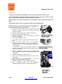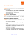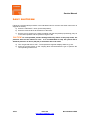
1
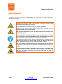
Service Manual
Proportioning Unit
Easy Spray
Issue 2.6 10/10/14
Ref. NR-00019-ENG
Before installing the unit and starting it up, read all the technical and
safety documentation included in this manual carefully. Pay special
attention to the information to know and understand the operation and the
conditions of use of the unit. All of the information is aimed at enhancing
User Safety and avoiding possible breakdowns derived from the incorrect
use of the unit.
Service Manual
WARRANTY
GARRAF MAQUINARIA, S. A. (hereinafter “GAMA”) provides this LIMITED WARRANTY (hereinafter “Warranty”) to the
original purchaser (hereinafter “Customer”) covering this equipment and the original GAMA manufactured accessories
delivered with the equipment (hereinafter “Product”) against defects in material or workmanship of the Product
(hereinafter “Defect” or “Defective”) for a period of two (2) years from the date of first purchase as shown on the original
GAMA invoice (hereinafter “Warranty Period”).
If during the Warranty Period under normal use, the Product is suspected by Customer to be Defective in material or
workmanship, it is Customer’s responsibility to contact GAMA and return the Product to GAMA as directed by GAMA,
freight prepaid. If GAMA determines that the Product is Defective and that such Defect is covered by this Warranty,
GAMA will credit Customer for the reasonable freight charges incurred by Customer in returning the Defective Product
to GAMA, and GAMA (or its authorized agent) will, at GAMA’s option, repair or replace the Product, subject to the
following:
Original Invoice: The original invoice must be kept as proof of the date of first sale and the Product serial number. The
Warranty does not cover any Product if the Original Invoice appears to have been modified or altered, or when the serial
number on the Product appears to have been altered or defaced.
Product Maintenance: It is the Customer’s responsibility to maintain the Product properly. See your maintenance
schedule and owner’s manual for details. The Warranty does not cover an improperly maintained Product.
Non-GAMA Components and Accessories: Non-GAMA manufactured components and accessories that are used in the
operation of the Product are not covered by this Warranty. Such components and accessories shall be subject to the
warranty offered to the Customer, if any, by the original manufacturer of such component or accessory.
Other Warranty Exclusions: The Warranty does not cover any Product that GAMA determines has been damaged or
fails to operate properly due to misuse, negligence, abuse, carelessness, neglect, or accident. By way of example only,
this includes:
Normal wear and tear.
Improper or unauthorized installation, repair, alteration, adjustment or modification of the Product.
Use of heating devices, pumping equipment, dispensers, or other parts or accessories with the Product that
have not been approved or manufactured by GAMA.
Failure to follow the operating instructions and recommendations provided by GAMA.
Cosmetic damage.
Fire, flood, “acts of God,” or other contingencies beyond the control of GAMA.
THE WARRANTY DESCRIBED HEREIN IS THE EXCLUSIVE REMEDY FOR THE CUSTOMER AND IS IN LIEU OF ALL OTHER
WARRANTIES, EXPRESS, IMPLIED, STATUTORY OR OTHERWISE, AND THE IMPLIED WARRANTIES OF MERCHANTABILITY
AND FITNESS FOR A PARTICULAR PURPOSE AND ALL OTHER WARRANTIES ARE HEREBY DISCLAIMED. TO THE FULLEST
EXTENT PERMITTED BY LAW, GAMA SHALL NOT BE RESPONSIBLE, WHETHER BASED IN CONTRACT, TORT (INCLUDING,
WITHOUT LIMITATION, NEGLIGENCE), WARRANTY OR ANY OTHER LEGAL OR EQUITABLE GROUNDS, FOR ANY
CONSEQUENTIAL, INDIRECT, INCIDENTAL, LOST PROFITS, SPECIAL, PUNITIVE OR EXEMPLARY DAMAGES, WHETHER TO
PERSON OR PROPERTY, ARISING FROM OR RELATING TO THE PRODUCT, EVEN IF GAMA HAS BEEN ADVISED OF THE
POSSIBILITY OF SUCH LOSSES OR DAMAGES.
Non-Warranty Service by GAMA: If GAMA determines that the suspected Defect of the Product is not covered by this
Warranty, disposition of the Product will be made pursuant to the terms and conditions of GAMA’s written estimate on a
time and materials basis.
Continuing Warranty for Products Repaired or Replaced under Warranty: Following the repair or replacement of a
Product covered by this Warranty, such Product will continue to be subject to the original Warranty for the remainder of
original Warranty Period or for three (3) months from the repair or replacement date, whichever is longer.No Rights
Implied: Nothing in the sale, lease or rental of any Product by GAMA shall be construed to grant any right, interest or
license in or under any patent, trademark, copyright, trade secret or other proprietary right or material owned by anyone;
nor does GAMA encourage the infringement of same.
Exclusive Warranty: This writing is the final, complete, and exclusive expression of the Warranty covering the Product.
Any statements made by GAMA, its employees or agents that differ from the terms of this Warranty shall have no effect.
It is expressly understood that Customer’s acceptance of this Warranty, by performance or otherwise, is upon and
subject solely to the terms and conditions hereof, and any additional or different terms and conditions proposed or
expressed by Customer or anyone, whether in writing or otherwise, are null and void unless specifically agreed to in
writing by an Officer of GAMA.
2/43
Issue 2.6
http://www.gamapur.com
Ref. NR-00019-ENG
Service Manual
All information provided in this Service Manual is assumed to be correct; although this does not
constitute any implicit or explicit liability or guarantee. GAMA reserves the right at any time and
without prior warning to make all improvements and modifications necessary to this Service
Manual, in order to rectify any possible typographical errors, supplement the information
contained or insert changes predicated by the performance or use of the unit.
SAFETY AND HANDLING
This chapter contains information on the safety, handling and use of the Easy Spray series
proportioning unit.
Before installing the unit and starting it up, read all the technical and
safety documentation included in this manual carefully. Pay special
attention to the information to know and understand the operation and the
conditions of use of the unit. All of the information is aimed at enhancing
User Safety and avoiding possible breakdowns derived from the incorrect
use of the unit.
WARNING! establishes information to alert on a situation that might cause serious
injuries if the instructions are not followed.
CAUTION! establishes information that indicates how to avoid damage to the unit or
how to avoid a situation that could cause minor injuries.
NOTE: is relevant information on a procedure being carried out.
Careful study of this manual will enable the operator to know the characteristics of the unit and
the operating procedures. By following the instructions and recommendations contained herein,
you will reduce the potential risk of accidents in the installation, use or maintenance of the unit;
you will provide a better opportunity for incident-free operation for a longer time, greater output
and the possibility of detecting and resolving problems fast and simply.
Keep this Service Manual for future consultation of useful information at all times. If you lose
this manual, ask for a new copy from your GAMA local distributor or directly contact Garraf
Maquinaria, S.A.
WARNING! The design of the Easy Spray series proportioning unit does not allow its
use in potentially explosive atmospheres or to exceed the pressure and temperature
limits described in the technical specifications of this manual.
3/43
Issue 2.6
http://www.gamapur.com
Ref. NR-00019-ENG
Service Manual
When working with the unit, it is recommended that the operator wear suitable clothing and
elements of personal protection, including, without limitation, gloves, protective goggles, safety
footwear and face masks. Use breathing equipment when working with the machine in
enclosed spaces or in areas with insufficient ventilation. The introduction and follow-up of
safety measures must not be limited to those described in this manual. Before starting up the
machine, a comprehensive analysis must be made of the risks derived from the products to be
dispensed, the type of application and the working environment.
To prevent all possible bodily harm caused by incorrect handling of the
raw materials and solvents used in the process, carefully read the safety
information provided by your supplier.
Deal with the waste caused according to current regulations.
Disconnect the unit from the power supply before carrying out any
operation inside the electrical console.
The electrical maintenance of the machine must only be performed by a
qualified electrician.
To avoid damage caused by the impact of pressurized fluids, do not open
any connection or perform maintenance work on components subject to
pressure until the pressure has been completely eliminated.
Use suitable protection when operating, maintaining or remaining in the
operating area of the unit. This includes, but is not limited to, the use of
masks, protective goggles, gloves, shoes and safety clothing.
The unit includes components that reach temperatures that are liable to
cause burns. The hot parts of the unit must not be handled until they
have cooled.
To prevent serious harm by crushing or loss of limbs, do not work with
the unit without the safety guards installed on all moving parts. Make
sure that all of the safety protections are correctly reinstalled after all
repair or maintenance work is completed.
4/43
Issue 2.6
http://www.gamapur.com
Ref. NR-00019-ENG
Service Manual
CHARACTERISTICS
The Easy Spray proportioning unit has been designed and built for the application of Polyureas,
chemical systems for polyurethane foaming, and some two-component Epoxy systems.
Its reduced size allows easy transport to site. Its easy operation (simply turn one switch and
push the START button) reverts into time saving during set up and application.
Principal Heating System
Consists of two independent heaters without seals. Each heater has two 900 W heating
elements, which give the unit a total power of 1800 W and the necessary control and safety
components for the precise operation of the system. Its peculiar configuration allows a
temperature differential (ΔT) of 30º C and application temperatures of up to 70º C under normal
conditions of ambient temperature.
Proportioning Pumps
Comprises two positive displacement piston pumps, driven by a pneumatic motor. The system
includes two pressure regulators that allow the working pressures to be equalized in the two
directions of pump movement, compensating for the imbalance of pressure caused by the
difference between the upper and the lower side of the air motor, and the effect of the additional
pressure of the transfer pumps.
5/43
Issue 2.6
http://www.gamapur.com
Ref. NR-00019-ENG
Service Manual
Recirculation System
Allows keeping the products in temperature prior to start spraying and during breaks.
Proportioning System (OPTIONAL)
Designed with a 2000 W isolation transformer
that enables effective heating up to a total
hose length of 48 meters (165 feet). The
system includes an innovative hose heating
concept in which the copper heating element is
spread evenly around the circumference of the
hose, providing a uniform heating watt density
and precise control of the product application
temperature.
6/43
Issue 2.6
http://www.gamapur.com
Ref. NR-00019-ENG
Service Manual
TECHNICAL SPECIFICATIONS EASY SPRAY-100
Electrical
Main Voltage: ____________________________________________________________ 230 V
Frequency: ____________________________________________________________ 50/60 Hz
Electrical Consumption: ______________________________________16 amp @ 1 x 400 V+ N
@ 2x 230 V
Total Active Power: ______________________________________________________ 3.6 Kw
Heater Power:_________________________________________________ (2 x 1.8 Kw) 3.6 Kw
Transformer Frequency (Optional): _________________________________________ 50/60 Hz
Transformer Active Power (Optional): __________________________________________ 2 Kw
Transformer Electrical Consumption (Optional): ____________________9 amp @ 1 x 400 V+ N
@ 2 x 230 V
Mechanical
Maximum Working Pressure (air supply 9 bar): ____________ 100 Kgf/cm² (9.8 MPa) / 1425 psi
Maximum Production Ratio 1:1: ____________________________________ 4 kg/min / 9 lb/min
Minimum Production: ___________________________________________ 1 kg/min / 2,2 lb/min
Recirculation Hose Length: __________________________________________________ 11 m
Maximum Heated Hose Length (Optional): ______________________________________ 48 m
Recommended Compressor: ______________________________________ 3,5 HP one-phase
Approximate weight: _________________________________________________ 80 kg /176 lbs
Dimensions: ______________________ H: 1000 mm (40”) / W: 610 mm (21”) / L: 700 mm (28”)
7/43
Issue 2.6
http://www.gamapur.com
Ref. NR-00019-ENG
Manual de Servicio
TECHNICAL SPECIFICATIONS EASY SPRAY-200
Electrical
Main Voltage: ____________________________________________________________ 230 V
Frequency: ____________________________________________________________ 50/60 Hz
Electrical Consumption: ______________________________________16 amp @ 1 x 400 V+ N
@ 2x 230 V
Total Active Power: ______________________________________________________ 3.6 Kw
Heater Power:_________________________________________________ (2 x 1.8 Kw) 3.6 Kw
Transformer Frequency (Optional): _________________________________________ 50/60 Hz
Transformer Active Power (Optional): __________________________________________ 2 Kw
Transformer Electrical Consumption (Optional): ____________________9 amp @ 1 x 400 V+ N
@ 2 x 230 V
Mechanical
Maximum Working Pressure (air supply 9 bar): ___________ 200 Kgf/cm² (19,7 MPa) / 2840 psi
Maximum Production Ratio 1:1: ____________________________________ 4 kg/min / 9 lb/min
Minimum Production: ___________________________________________ 1 kg/min / 2,2 lb/min
Recirculation Hose Length: __________________________________________________ 11 m
Maximum Heated Hose Length (Optional): ______________________________________ 48 m
Recommended Compressor: _____________________________________ 7,5 HP three-phase
Approximate weight: _________________________________________________ 80 kg /176 lbs
Dimensions: ______________________ H: 1000 mm (40”) / W: 610 mm (21”) / L: 700 mm (28”)
8/43
Issue 2.6
http://www.gamapur.com
Ref. NR-00019-ENG
Service Manual
GENERAL DESCRIPTION
Figure 1.
9/43
General Description Easy Spray
Issue 2.6
http://www.gamapur.com
Ref. NR-00019-ENG
Service Manual
1. Isocyanate Tank
Contains the A chemical element. Capacity 30 liters.
2. Polyol Tank
Contains the R chemical element. Capacity 30 liters.
3. Isocyanate Recirculation Valve
Allows selecting recirculation or spraying in the Isocyanate circuit.
4. Polyol Recirculation Valve
Allows selecting recirculation or spraying in the Polyol circuit.
5. Control Panel
Controls and regulates the correct operation of the unit.
6. Isocyanate Proportioning Pump
Meters the Isocyanate.
7. Polyol Proportioning Pump
Meters the Polyol.
8. Isocyanate Heater
Heats the Isocyanate to the pre-set temperature.
9. Polyol Heater
Heats the Polyol to the pre-set temperature.
10. Hose Heating Transformer (Optional)
Supplies the required voltage for heating the hoses.
11. Hose Electrical Regulator (Optional)
Set the electric power desired for heating the hoses.
12. Isocyanate Pressure Gage
Indicates the pressure in the Isocyanate circuit.
13. Polyol Pressure Manometer
Indicates the pressure in the Polyol circuit.
14. Isocyanate Heater Probe
Provides information on the temperature of the Isocyanate
15. Polyol Heater Probe
Provides information on the temperature of the Polyol.
16. Isocyanate Inlet Filter
Avoids the penetration of solid particles inside the Isocyanate pump of the unit.
17. Polyol Inlet Filter
Avoids the penetration of solid particles inside the Polyol pump of the unit.
18. Main Pneumatic Valve
It opens and closes the flow of air coming into the pneumatic system.
19. Retract Valve
Sets the piston rod of the Isocyanate proportioning pump to the retract position and prevents the
crystallization of Isocyanate on the piston rod. Close the RETRACT valve every time the unit is
stopped by the operator.
20. Pressure Regulators
Using the two air pressure regulators, select the pressure for the down stroke and the up stroke
of the pneumatic cylinder.
10/43
Issue 2.6
http://www.gamapur.com
Ref. NR-00019-ENG
Service Manual
CONTROL PANEL AND HOSE HEATED SYSTEM
Figure 2.
Control Panel and Hose Heating
Comprises two electrical components for an accurate working of the unit.
1. Main Power Switch
Turns the electric supply to the control panel on and off. It must be turned ON for any operation
to be performed with the unit.
2. Start Button
This pushbutton turns the circuit control on.
3. ISO/POL Temperature Regulator
Establishes the temperature needed for every
product.
Note:
To manipulate the device, refer to the specific chapter
“Regulator of Temperature Heaters”.
11/43
Issue 2.6
http://www.gamapur.com
Ref. NR-00019-ENG
Manual de Servicio
4. Hoses (OPTIONAL)
Hose heating is activated and deactivated by
the orange pushbutton located at the front of
the transformer. It will lit up when heating is
activated.
Turn the potentiometer clockwise to increase
amps, and anti-clockwise if you wish to
decrease amps. Adjustment ranges from 0 to
50 amps.
Take the values below as an approximate
reference to select the intensity that allows
reaching
the
requested
application
temperature.
30 A
35 A
40 A
45 A
50 A
38º C
48º C
60º C
75º C
90º C
100º F
118º F
140º F
167º F
194º F
Turn the potentiometer clockwise until the screen shows the required amps for a quick preheating.
NOTE: The circuit breaker software of the transformer has a safety system to prevent
the hoses from being exposed to high temperatures during long periods of time.
If you have selected a potential over 35 amperes, after 20 minutes, the potential will
automatically regulate to 35 amperes.
This potential cannot be set above 35 amperes until the heater is disconnected from the
hoses and reconnected.
5. Heaters Switch
Turns the electric supply to the control heaters unit ON and OFF.
12/43
Issue 2.6
http://www.gamapur.com
Ref. NR-00019-ENG
Service Manual
REGULATOR OF TEMPERATURE HEATERS
This machine equips each heater with separate temperature regulators.
Instructions
When the power is connected to the machine, the displays will show the current temperature
values.
To modify the values press
or
as required.
For more details about the settings, follow the instructions from the manufacturer's manual
attached.
.
NB:
The temperature regulators are not inter-changeable with those attached to
previous versions of the machine.
13/43
Issue 2.6
http://www.gamapur.com
Ref. NR-00019-ENG
Manual de Servicio
INSTALLATION (RECIRCULATION UNIT)
CAUTION! Use suitable protection and follow the recommendations in the safety
information provided by product suppliers when installing or working with the unit.
NOTE: To ensure that the unit works correctly, the electrical supply must meet the
specifications indicated on page six of this manual and appearing on the machine
specifications plate.
Follow the recommended procedure in the indicated order to
install the unit:
a) Fill the Isocyanate pump lubricating cup with DOP
plasticizer.
b) Connect the pressure hose of each product to the
outlet of the respective heaters (the Isocyanate hose to
the Isocyanate heater and the Polyol hose to the
Polyol heater).
c) Connect the recirculation hose of each product to the
recirculation valves located in the ISO or POLY tank.
(the Isocyanate hose to the Isocyanate tank valve and
the same in the Polyol side).
NOTE: The product hoses have been identified with red (Isocyanate) and blue (Polyol),
enabling them to be rapidly distinguished. To avoid errors in connecting the coupling
connectors of the Isocyanate and Polyol hoses, the connectors are of different sizes to
make it impossible for connections to be swapped.
Figure 3. Method
of union of the Hoses
WARNING! To join the hoses together or to connect them to the heaters or the gun,
use two spanners to hold the parts to be joined (1) and a third spanner to tighten or
loosen the connecting nut (2) as shown in the illustrations in Figure 3 on page 14. The
connections must be tightened to a torque of 20 Nm.
14/43
Issue 2.6
http://www.gamapur.com
Ref. NR-00019-ENG
Service Manual
d) Connect the air hoses.
e) Connect the two pressure hoses to the connectors of the coupling block of the gun,
making sure that the manual valves are closed. (the Polyol hose to the Polyol connector
and the Isocyanate hose to the Isocyanate connector).
f) Connect the recirculation hoses to the connectors of the coupling block of the gun.
g) Insert a contact thermometer through the hose insulation so that the bottom of the
thermometer is in contact with the hoses and the top is outside the insulation. Fit the
thermometer in such a way that the operators can see the temperature when they are
spraying.
h) Fill the Isocyanate and Polyol tank.
WARNING!
To prevent possible bodily harm caused by incorrect handling of the raw materials and
solvents used in the process, carefully read the safety information provided by your
supplier.
To avoid splashing, open only the lid of the tank (Isocyanate or Polyol) where the product
will be poured.
Never change the chemical components, use always the same tank for each component.
15/43
Issue 2.6
http://www.gamapur.com
Ref. NR-00019-ENG
Manual de Servicio
WARNING!
In order to avoid product contamination, make sure that the tanks are well closed.
Do not fill the tank to maximum capacity; check the level on the tank to make sure that
20% of its maximum capacity is vacant. Each tank is 30 liters.
Small vessels (10-15 liters maximum) are recommended to pour the product inside the
tanks.
Fill the tanks with the amount of product required for each application.
Before using the unit, the retained air and the residual oil from
the operating tests made in the factory must be eliminated. To
purge the whole circuit, proceed as follows:
a) Remove the recirculation hoses and place them in two
separate vessels to gather up the products contained
inside the machine.
b) Open the manual valves at the bottom of the tanks.
c) Open the manual recirculation valves.
d) Turn the “RETRACT” valve as it appears (in vertical
position it’s opened).
e) Turn the general switch “ON”.
f) Turn the air pressure regulators anti-clockwise until the
end.
g) Push the “START” green button. The temperature
regulator displays will light on, (whenever the switch of
the heaters is in “On“). Check the product pumps begin
to move slowly.
If necessary, increase the pneumatic pressure by
turning the regulator clockwise until the product pumps
begin to move slowly.
h) Allow the materials to come out of the recirculation hose
until the residual oil and the air bubbling has disappeared
completely.
i) Close the product recirculation valves.
j) Clean the recirculation hoses and place them to their
tanks again.
k) Slowly increase the pneumatic pressure to check for
product leaks in the hose connections.
l) Close the “RETRATC” valve (horizontal position).
m) Turn the general switch “OFF”. The temperature
regulator displays will go out. The machine is ready.
16/43
Issue 2.6
http://www.gamapur.com
Ref. NR-00019-ENG
Service Manual
START-UP PROCEDURES
Follow the recommended procedure in the indicated order.
CAUTION! The start-up procedures assume that all of the necessary adjustments have
been correctly performed.
a) Check the state of the DOP plasticizer in the Isocyanate pump lubrication cup. Change
the oil if you see changes in the color or signs of solidification and retighten the packing
nut to ensure the seal.
b) Make sure the chemical tanks are fill of material.
c) Check the inlet filters of the products. Clean them if necessary.
d) Open the product manual valves at the bottom of the tanks.
e) Open the manual recirculation valves.
NOTE: Do this if you’re willing to recirculate products.
NOTE: Product recirculation allows reaching the set up temperature in the heaters
quicker, heating the hoses and the gun at the same time. For more effectiveness for
heating the products whilst recirculating, fill the product tanks with the minimum
quantity required.
CAUTION! Product tanks are made of a plastic material which resists up to 80 ºC.
Product temperature inside the tanks must never reach that limit.
CAUTION! Do not recirculate with full tanks, since over pressure may occur in the
interior of the tanks.
f) Turn the general switch “ON”.
g) Open the “RETRATC” valve, (vertical position).
h) Push the “START” green button. The temperature regulator displays will light on,
(whenever the switch of the heaters is in “On“). Check the product pumps begin to
move slowly.
i) Using the air pressure regulators, first of all select the pressure for the down stroke of
the proportioning pumps and then adjust the pressure for the up stroke. The pressures
must be practically the same and remain constant.
j) If the pressures fluctuate on each stroke, check the troubleshooting section before
continuing.
k) Set the temperature on the Isocyanate Regulator
l) Set the temperature on the Polyol Regulator.
m) Connect the air supply to the gun.
n) Close the recirculation valves; should these be open, open the manual gun valves of
each product; make a test projection and check the pressures on the product gauges. If
the projection test is correct and the pressures remain equal, proceed with the
application.
17/43
Issue 2.6
http://www.gamapur.com
Ref. NR-00019-ENG
Service Manual
DAILY SHUTDOWN
Follow the recommended procedure in the indicated order for machine shut down when work is
stopped for the day.
a) Close the “RETRACT” valve, (horizontal position).
b) Close the manual valves at the bottom of the tanks.
c) Use the gun to project into a waste container until the Isocyanate proportioning pump is
in the retract position and the pressure begins to fall.
CAUTION! To avoid possible product leakage and early failure of the pump seals, the
pressure must not be reduced to zero. It is recommended to keep the system with a
minimum pressure of 30 bar (400 psi) to extend the life of the seals.
d) Turn the general switch “OFF”. The temperature regulator displays will then go out.
e) Close the manual valves on the coupling block and dismantle the gun to perform the
corresponding maintenance.
18/43
Issue 2.6
http://www.gamapur.com
Ref. NR-00019-ENG
Service Manual
CLEANING
CAUTION! The unit includes components that reach temperatures that are liable to
cause burns. The hot parts of the unit must not be handled until they have cooled.
To avoid possible contamination, the circuits of the unit must be flushed clean (pumps, heaters
and hoses) whenever applications have to be made that require a change of components.
Follow the recommended procedures in the order indicated to perform the cleaning:
a) Remove the recirculation hoses and place them in two separate vessels to gather up
the products contained inside the machine.
NOTE: Should the products be used again, use a proper vessel to store them, following
the instructions from your product supplier.
b)
c)
d)
e)
f)
g)
h)
i)
j)
k)
l)
m)
n)
o)
p)
q)
r)
s)
t)
u)
v)
19/43
Open the manual valves at the bottom of the tanks.
Open the manual recirculation valves.
Open the “RETRACT” valve, (vertical position).
Turn the general switch “ON”.
Turn the air pressure regulator anti-clockwise until the end.
Push the “START” green button. The temperature regulator displays will light on,
(whenever the switch of the heaters is in “On“). Check the product pumps begin to
move slowly.
If necessary, increase the pneumatic pressure by turning the regulator clockwise until
the product pumps begin to move slowly.
Allow the materials to come out of the recirculation hose until the tanks are completely
empty.
Turn the general switch “OFF”. The temperature regulator displays will then go out.
Close the product manual valves at the bottom of the tanks.
Fill the component tanks using DOP cleaning agent (about 5 liters in each tank).
Open the product manual valves at the bottom of the tanks.
Place the recirculation hoses to their tanks again and make sure the recirculation valves
are open.
Dismantle the gun and leave the coupling block connected to the hoses. Make sure the
gun valves are closed.
Turn the general switch “ON”.
Push the “START” button. The temperature regulator displays will light on, (whenever
the switch of the heaters is in “On“). Check that the product pumps move.
Maintain the unit recirculating for about 2-3 minutes to clean the hoses and the tanks.
For a more efficient cleaning of the tanks, the cleaning agent can be heated through the
heaters.
Turn the general switch “OFF”. The temperature regulator displays will then go out.
Remove the recirculation hoses of the Isocyanate and Polyol tanks again and place
them in two separate waste vessels.
Turn “off” the “heaters” switch.
Turn the general switch “ON”.
Push the “START” green button, the temperature regulator not will light on. Check the
product pumps begin to slowly move.
Issue 2.6
http://www.gamapur.com
Ref. NR-00019-ENG
Service Manual
w)
x)
y)
z)
aa)
bb)
cc)
dd)
ee)
ff)
gg)
hh)
ii)
jj)
kk)
ll)
20/43
Allow the materials to come out of the recirculating hoses until the tanks are empty.
Turn the general switch “OFF”.
Close the manual valves at the bottom of the tanks.
Close the recirculation manual valves.
Fill the product tanks with new product.
Open the manual valves at the bottom of the tanks.
Open the recirculation manual valves.
Turn the general switch “ON”.
Push the “START” green button. The temperature regulator displays not will light on.
Check the product pumps begin to move slowly.
If necessary, increase the pneumatic pressure by turning the regulator clockwise until
the product pumps begin to move slowly.
Allow the DOP agent to come out of the recirculation hose until see the new product.
Allow the products to come out until you see that only DOP cleaning agent comes out
free of impurities.
Close the “RETRATC” valve (horizontal position).
Turn the general switch “OFF” and return to the position “On“ the switch of the heaters.
Clean and move the recirculation hoses to the tanks again.
Close the manual valves at the bottom of the tanks.
The cleaning process is complete and you can proceed as normal for new products.
Issue 2.6
http://www.gamapur.com
Ref. NR-00019-ENG
Service Manual
SHUTDOWN PROCEDURES
CAUTION! The unit includes components that reach temperatures that are liable to
cause burns. The hot parts of the unit must not be handled until they have cooled.
When you plan to shut down the machine for more than five weeks, the products contained in
the machine must be replaced by DOP plasticizing agent.
Follow the recommended procedures in the order indicated:
Remove the recirculation hoses and place them in two separate vessels to gather up the
products contained inside the machine.
NOTE: Should the products be used again, use a proper vessel to store them, following
the instructions from your product supplier.
a)
b)
c)
d)
e)
f)
g)
h)
i)
j)
k)
l)
m)
n)
o)
p)
q)
r)
s)
t)
u)
21/43
Open the manual valves at the bottom of the tanks.
Open the manual recirculation valves.
Open the “RETRACT” valve (vertical position).
Turn the general switch “ON”. Using the air pressure regulators, turn anti-clockwise until
the end.
Push the “START” green button. The temperature regulator displays will light on,
(whenever the switch of the heaters is in “On“). Check the product pumps begin to
move slowly.
If necessary, increase the pneumatic pressure by turning the regulator clockwise until
the product pumps begin to move slowly.
Allow the materials to come out of the recirculation hose until the tanks are completely
empty.
Turn the general switch “OFF”. The temperature regulator displays will then go out.
Close the product manual valves at the bottom of the tanks.
Fill the component tanks using DOP cleaning agent (about 5 liters in each tank).
Open the product manual valves at the bottom of the tanks.
Place the recirculation hoses to their tanks again and make sure the recirculation valves
are open.
Dismantle the gun and leave the coupling block connected to the hoses. Make sure the
gun valves are closed.
Turn the general switch “ON”.
Push the “START” green button. The temperature regulator displays will light on,
(whenever the switch of the heaters is in “On“). Check that the product pumps move.
Maintain the unit recirculating for about 2-3 minutes to clean the hoses and the tanks.
For a better cleaning of the tanks, the cleaning agent can be heated through the
heaters.
Turn the general switch “OFF”. The temperature regulator displays will then go out.
Remove the recirculation hoses again and place them in two separate vessels to gather
up the products contained inside the machine.
Turn the general switch “ON”.
Push the “START” green button, the temperature regulator will light on, (whenever the
switch of the heaters is in “On“). Check the product pumps begin to slowly move.
Allow the materials to come out of the recirculation hoses until the tanks are empty.
Issue 2.6
http://www.gamapur.com
Ref. NR-00019-ENG
Service Manual
v)
w)
x)
y)
z)
aa)
bb)
cc)
dd)
ee)
ff)
Turn the general switch “OFF”. The temperature regulator will go out.
Close the manual valves at the bottom of the tanks.
Close the recirculation manual valves.
Move the recirculation hoses to the tanks again and make sure that the manual valves
are open.
Fill the component tanks using DOP cleaning agent, about 5 liters in each tank.
Close the recirculation manual valves.
Turn the general switch “ON”.
Push the “START” green button. The temperature regulator displays will light on,
(whenever the switch of the heaters is in “On“). Check that the product pumps move.
Turn the general switch “OFF”. The temperature regulator displays will then go out.
Close the “RETRACT” valve (horizontal position).
Reduce the pressure of the products by opening the recirculation valves in the tanks
and closing them immediately after.
To avoid possible product leakage and the early failure of the pump seals, the pressure
must not be reduced to zero. It is recommended to keep the system with a minimum
pressure of 30 bar (400 psi) to extend the life of the seals.
Never leave the machine or the hoses empty of product or DOP plasticizing oil.
22/43
Issue 2.6
http://www.gamapur.com
Ref. NR-00019-ENG
Service Manual
INSTALATION (HEATED HOSES UNIT)
CAUTION! Use suitable protection and follow the recommendations in the safety
information provided by product suppliers when installing or working with the unit.
NOTE: To ensure that the unit works correctly, the electrical supply must meet the
specifications indicated on page six of this manual and appearing on the machine
specifications plate.
Follow the recommended procedure in the indicated order to install the unit:
a) Fill the Isocyanate pump lubricating cup with DOP plasticizer.
b) Connect the hoses of the products to the outlets of the respective heaters (the
Isocyanate hose to the Isocyanate heater and the Polyol hose to the Polyol heater).
NOTE: The product hoses have been identified with red (Isocyanate) and blue (Polyol),
enabling them to be rapidly distinguished. To avoid errors in connecting the coupling
connectors of the Isocyanate and Polyol hoses, the connectors are of different sizes to
make it impossible for connections to be swapped.
The hoses receive vacuum drying treatment and are supplied interconnected at the ends to
prevent them from absorbing moisture. Do not separate them until they are going to be
installed in the unit.
The hose connection system includes special terminals (fast lock) to facilitate the electrical
connection to the transformer and between the different sections installed in the unit.
The transformer offers the option of connecting to a 40 V output voltage valid for a total hose
length of up to 48 meters.
c) Connect the heated hoses wires to the “fast
lock” connector coming out of the hose
transformers as follow:
a. Unscrew the Nylon Safety Plug from the
“fast lock” connector body.
b. Unscrew partially the Socket Head Set
Screw from electrical wires.
c. Insert the heated hose electrical wire
with terminals into the “fast lock”
connector body.
d. Tighten the Socket Head Set Screw of
the terminals and place the Nylon
Safety Plugs
Repeat the same steps to connect the “fast lock” that
you will find in the middle hose connections.
d) Connect the rest of the product hoses to complete the required length. Remember that
the hoses are identified with red (Isocyanate) and blue (Polyol).
WARNING! To join the hoses together or to connect them to the heaters or the gun,
use two spanners to hold the parts to be joined (1) and a third spanner to tighten or
loosen the connecting nut (2) as shown in the illustrations in Figure 3 on page 14. The
connections must be tightened to a torque of 20 Nm.
23/43
Issue 2.6
http://www.gamapur.com
Ref. NR-00019-ENG
Manual de Servicio
NOTE: Assure the proper mechanical and electrical connection of the hoses to avoid
possible product leakage and hose heat problems.
e) Connect the air hoses.
f) Connect the hoses to the connectors of the coupling block of the gun, making sure that
the manual valves are closed.
g) Insert a contact thermometer through the hose insulation so that the bottom of the
thermometer is in contact with the hoses and the top is outside the insulation. Fit the
thermometer in such a way that the operators can see the temperature when they are
spraying. If the hoses have STC probes to automatically control the temperature, the
contact thermometer will not have to be installed.
h) Fill the Isocyanate and Polyol Tank
24/43
Issue 2.6
http://www.gamapur.com
Ref. NR-00019-ENG
Service Manual
WARNING!
To prevent possible bodily harm caused by incorrect handling of the raw materials and
solvents used in the process, carefully read the safety information provided by your
supplier.
To avoid splashing open only one tank Isocyanate or Polyol.
Never change the chemical components, use always the same tank for each component.
In order to avoid product contamination, make sure that the tanks are well closed.
Do not fill the tank to its maximum capacity; check the level on the tank to make sure that
20% of its maximum capacity is vacant. Each tank is 30 liters.
Small vessels (10-15 liters maximum) are recommended to pour the product inside the
tanks.
Fill the tanks with the amount of product required for each application.
Before using the unit, the retained air and the residual oil from the operating tests made in the
factory must be eliminated. To purge the whole circuit, proceed as
follows:
a) Keep the coupling block with the outlet of each product in
separate vessels and open the manual valves of each
product.
b) Turn the pneumatic pressure regulator counter clockwise
as far as it will go.
c) Open the manual valves at the bottom of the tanks.
d) Turn the “RETRATC” valve as it appears (in vertical
position it’s opened).
e) Turn the general switch “ON”.
f) Push the “START” green button. The temperature
regulator displays will light on, (whenever the switch of the
heaters is in “On“). Check the product pumps begin to
slowly move.
Allow the materials to come out of the coupling block until
the residual oil and the air bubbling has disappeared
completely.
g) Close the manual valves of each product and clean the
coupling block of the remaining supply of product.
h) Slowly increase the pneumatic pressure to check for
product leaks in the hose connections. Retighten if
necessary and tape the connectors to protect them from
possible damage.
i) Close the “RETRACT” valve (horizontal position).
j) Turn the general switch “OFF”. The temperature regulator
will go out.
k) Mount the gun on the coupling block.
25/43
Issue 2.6
http://www.gamapur.com
Ref. NR-00019-ENG
Manual de Servicio
START UP PROCEDURES
Follow the recommended procedure in the indicated order.
CAUTION! The start-up procedure assumes that all of the necessary adjustments have
been correctly performed.
a) Check the state of the DOP plasticizer in the Isocyanate pump lubrication cup. Change
the oil if you see changes in the color or signs of solidification and retighten the packing
nut to ensure the seal.
b) Make sure the level of the chemical tanks is enough to process the system.
c) Check the inlet filters of the products. Clean them if necessary.
d) Open the manual valves at the bottom of the tanks.
e) Turn the potentiometer located on the transformer to apply the electrical intensity to the
heating hose system. (See Amps table on page 12).
Selected intensity must not be maintained over 10 minutes. After that
time, turn the potentiometer anti-clockwise until the screen shows
25amps.
To avoid excessive pressure in the heated hoses, wait for the product in
them to reach the required temperature before starting up the air motor
system.
f) Turn the general switch “ON”.
g) Open the “RETRATC” valve (vertical position).
h) Push the “START” green button, the temperature regulator displays will light on,
(whenever the switch of the heaters is in “On“).
i) Set the Isocyanate Temperature on the Iso Regulator.
j) Set the Polyol Temperature on the Poly Regulator.
k) Using the air pressure regulators, first of all select the pressure for the down stroke of
the proportioning pumps and then adjust the pressure for the up stroke. The pressures
must be practically the same and remain constant. If the pressures fluctuate on each
stroke, consult the fault section before continuing.
l) Connect the air supply to the gun; open the manual valves of each product; make a test
projection and check the pressures on the product gages. If the projection test is correct
and the pressures remain equal, proceed with the application
26/43
Issue 2.6
http://www.gamapur.com
Ref. NR-00019-ENG
Service Manual
SHUTDOWN PROCEDURES
Follow the recommended procedure in the indicated order for machine shut down when work is
stopped for the day.
a) Close the “RETRACT” valve (horizontal position).
b) Close the manual valves at the bottom of the tanks.
c) Use the gun to project into a waste container until the Isocyanate proportioning pump is
in the retract position and the pressure begins to fall.
CAUTION! To avoid possible product leakage and the early failure of the pump seals,
the pressure must not be reduced to zero. It is recommended to keep the system with a
minimum pressure of 30 bar (400 psi) to extend the life of the seals.
d) Turn the general switch “OFF”. The temperature regulator will go out.
e) Remove the contact thermometer and roll up the heated hoses.
f) Close the manual valves on the coupling block and remove the gun to perform the
corresponding maintenance.
27/43
Issue 2.6
http://www.gamapur.com
Ref. NR-00019-ENG
Manual de Servicio
CLEANING
CAUTION! The unit includes components that reach temperatures that are liable to
cause burns. The hot parts of the unit must not be handled until they have cooled.
To avoid possible contamination, the circuits of the unit must be flushed clean (pumps, heaters
and hoses) whenever applications have to be made that require a change of components.
Follow the recommended procedures in the order indicated to perform the cleaning:
a) Dismantle the gun and leave the coupling block connected to the hoses.
b) Open the manual valves at the bottom of the tanks.
c) Place 2 separate vessels under the coupling block to gather up the products contained
inside the machine.
d) Open the manual valves on the coupling block.
e) Open the “RETRACT” valve (vertical position).
f) Turn the general switch “ON”. Using the air pressure regulators, turn anti-clockwise until
the end.
g) Push the “START” green button, the temperature regulator will light on, (whenever the
switch of the heaters is in “On“), check the product pumps begin to slowly move.
If necessary, increase the pneumatic pressure by turning the regulator clockwise.
h) Allow the materials to come out of the coupling block until the tanks are empty.
i) Close the manual valves on the coupling block.
j) Turn the general switch “OFF”. The temperature regulator will go out.
k) Close the manual valves at the bottom of the tanks.
l) Fill the component tanks using DOP cleaning agent, about 5 liters each one.
m) Open the manual valves at the bottom of the tanks.
n) Place 2 separate vessels under the coupling block to gather up the DOP contained
inside the machine.
o) Open the manual valves on the coupling block.
p) Turn the general switch “ON”.
q) Push the “START” green button, the temperature regulator will light on, (whenever the
switch of the heaters is in “On“). Check the product pumps begin to slowly move.
r) Allow the materials to come out of the coupling block until the tanks are empty.
s) Turn the general switch “OFF”. The temperature regulator will go out.
t) Close the manual valves at the bottom of the tanks.
u) Fill the component tanks using new chemical product.
v) Open the manual valves at the bottom of the tanks.
w) Turn the general switch “ON”.
x) Push the “START” green button, the temperature regulator displays will light on,
(whenever the switch of the heaters is in “On“). Check the product pumps begin to
slowly move.
If necessary, increase the pneumatic pressure by turning the regulator clockwise.
y) Allow the products to come out until you see that only DOP cleaning agent comes out
free of impurities.
z) When the products come out without the contamination produced by the effect of the
DOP cleaning agent, the cleaning process is complete and you can proceed as normal.
28/43
Issue 2.6
http://www.gamapur.com
Ref. NR-00019-ENG
Service Manual
aa)
bb)
cc)
dd)
ee)
29/43
Close the “RETRATC” valve (horizontal position).
Turn the general switch “OFF”. The temperature regulator displays will go out.
Close the coupling block and mount the gun.
Close the manual valves at the bottom of the tanks.
Follow the Start up Procedures if change the chemical products.
Issue 2.6
http://www.gamapur.com
Ref. NR-00019-ENG
Manual de Servicio
LONG-TERM SHUTDOWN PROCEDURES
CAUTION! The unit includes components that reach temperature that are liable to
cause burns. The hot parts of the unit must not be handled until they have cooled.
When you plan to shut down the machine for more than five weeks, the products contained in
the machine must be replaced by DOP plasticizing agent.
Follow the recommended procedures in the order indicated:
a) Place two drums of DOP cleaning agent close to the machine.
b) Dismantle the gun and leave the coupling block connected to the hoses.
c) Place 2 separate vessels under the coupling block to gather up the products contained
inside the machine.
d) Open the manual valves on the coupling block.
e) Open the manual valves at the bottom of the tanks.
f) Open the “RETRACT” valve (vertical position).
g) Turn the general switch “ON”. Using the air pressure regulators, turn anti-clockwise until
the end.
h) Push the “START” green button, the temperature regulator will light on, (whenever the
switch of the heaters is in “On“). Check the product pumps begin to slowly move.
If necessary, increase the pneumatic pressure by turning the regulator clockwise.
i) Allow the materials to come out of the coupling block until the tanks are empty.
j) Turn the general switch “OFF”. The temperature regulator will go out.
k) Close the manual valves at the bottom of the tanks.
l) Fill the component tanks using DOP cleaning agent, about 5 liters each one.
m) Open the manual valves at the bottom of the tanks.
n) Turn the general switch “ON”.
o) Push the “START” green button, the temperature regulator will light on, (whenever the
switch of the heaters is in “On“). Check the product pumps begin to slowly move.
p) Turn the general switch “OFF”. The temperature regulator will go out.
q) Close the “RETRATC” valve (horizontal position).
CAUTION! To avoid possible product leakage and the early failure of the pump seals,
the pressure must not be reduced to zero. It is recommended to keep the system with a
minimum pressure of 30 bar (400 psi) to extend the life of the seals.
The proportioning pumps, the heaters and the hoses must be full of DOP plasticizing oil.
Never leave the machine or the hoses empty of product or DOP plasticizing oil.
30/43
Issue 2.6
http://www.gamapur.com
Ref. NR-00019-ENG
Service Manual
TROUBLESHOOTING
The Easy Spray unit has been designed and built to withstand severe working conditions with a
high degree of reliability, provided it is used suitably. This chapter contains information on
possible faults that may prevent the continuation of work with the unit. The information provided
must serve as guideline to detect and resolve the large majority of the problems before calling
for the assistance of the authorized distributor or GAMA technical service. In any case, feel
free to contact the technical assistance service of Garraf Maquinaria, S.A. where a qualified
technician will advise you on whatever you may need.
NOTE: All repairs performed by unqualified personnel or the use of spares other than
originals may cause damage to the unit and put the operator at risk.
To prevent possible bodily harm caused by incorrect handling of the raw
materials and solvents used in the process, carefully read the safety
information provided by your supplier.
Deal with the waste caused according to current regulations.
Disconnect the unit from the power supply before carrying out any
operation inside the electrical console.
The electrical maintenance of the machine must only be performed by a
qualified electrician.
To avoid damage caused by the impact of pressurized fluids, do not open
any connection or perform maintenance work on components subject to
pressure until the pressures have been completely eliminated.
Use suitable protection when operating, maintaining or remaining in the
operating area of the unit. This includes, but is not limited to, the use of
face masks, protective goggles, gloves, shoes and safety clothing.
The unit includes components that reach temperature that are liable to
cause burns. The hot parts of the unit must not be handled until they
have cooled.
To prevent serious harm by crushing or loss of limbs, do not work with
the unit without the safety duly installed on all moving parts. Make sure
that all of the safety protections are correctly fitted after all repair or
maintenance work.
31/43
Issue 2.6
http://www.gamapur.com
Ref. NR-00019-ENG
Manual de Servicio
Heaters
WARNING! Before resolving any kind of defect, make sure all of the pushbuttons are
off, that the general switch is in shutdown position and that the unit is disconnected from
the power supply. Never handle the inside of the control panel with the unit connected to
the main power supply. The heaters are components that reach high temperatures; wait
until they have cooled before handling.
NOTE: The thermostat is a safety
element in contact with the heater. If
the temperature exceeds 120º C (248º
F) the thermostat will cut off the
electric supply by deactivating the
POWER CONTROL. The thermostat
will not reset until the temperature in
the heater is below 120º C (248º F).
1. Heating Elements
Each heater includes two 900 W heating
elements connected in parallel, which
give the system a total power of 1800 W.
If under normal conditions of room
temperature it is not possible to reach the
required temperature in two or three
minutes, it is possible that several heating
elements are not working.
To check the state of the elements,
proceed as follows:
To check the state of the element,
proceed as follows:
With the main switch off check with a
tester that reading the total value of the
heater resistance is indicated in the table
according to the power, voltage and
number for each installed heater
elements, a higher value would indicate
that one or more elements are faulty .
32/43
Issue 2.6
http://www.gamapur.com
Ref. NR-00019-ENG
Service Manual
Disconnect them and check that the individual value of each element is as shown in the table
according to the installed power and voltage.
Table 1. Elements Values List
(W)
(V)
x1 (Ω)
x2 (Ω)
x4 (Ω)
x6 (Ω)
450
230
117±2
58±2
29±2
19±2
900
230
58±2
29±2
14±2
9±2
900
400
177±2
88±2
44±2
29±2
1250
230
42±2
21±2
10±2
7±2
1250
400
128±2
64±2
32±2
21±2
1250
440
154±2
77±2
38±2
25±2
1500
230
35±2
17±2
8±2
5±2
1500
400
106±2
53±2
26±2
17±2
1500
440
129±2
64±2
32±2
21±2
1800
230
29±2
14±2
7±2
4±2
1800
400
88±2
44±2
22±2
14±2
1800
440
107±2
53±2
26±2
17±2
2000
230
26±2
13±2
6±2
4±2
2000
400
80±2
40±2
20±2
13±2
2000
440
96±2
48±2
24±2
16±2
Under extreme environmental conditions, the heater might be affected and fail to reach the
required temperature. In this case, put the unit in a more favorable place, or use an auxiliary
heating system.
2. Automatic Switch
This protects the elements against any possible change in voltage. With the general switch
turned off, open the control panel and make sure the switch is activated (see electrical
diagram), otherwise activate it.
3. Temperature
The temperature regulator automatically detects any fault in the operation of the temperature
probe. The device display “- - - -“.
If the fault occurs, replace the probe, paying special attention not to damage it when
assembling. The probe must be in firm physical contact with the element.
33/43
Issue 2.6
http://www.gamapur.com
Ref. NR-00019-ENG
Manual de Servicio
Hose Heating (Optional)
WARNING! Before resolving any kind of defect, make sure all of the pushbuttons are
off, that the general switch is in shutdown position and that the unit is disconnected from
the power supply source. Never handle the inside of the control panel with the unit
connected to the power supply. The hoses can reach high temperatures; wait until they
have cooled before handling.
Follow the recommended procedure in the order indicated, to try to solve the problem and avoid
costly repairs. Make sure all the automatic switches and control elements are in the correct
working position before determining the existence of a fault.
PROBLEMS
SOLUTIONS
The hose is hot, but fails to reach the selected temperature.
The hose is not hot.
1-2
2-3-4-5
Only the sections of the hose closest to the unit are heated.
5
The automatic switch trips.
3
SOLUTIONS
1. Hose Length
The Easy Spray has been designed to work with a maximum hose length of 48 meters /160 ft.
A longer length will render the heating capacity less effective. Under extreme environmental
conditions, the hose heating system may be affected and fail to reach the required temperature.
2. Hose Transformer
The transformer offers the option of connecting to a 40 V output voltage valid for the connection
of hose sections with a total length of up to 48 meters. If the connection is performed incorrectly,
the hoses will not reach the required temperature. On the transformer display appears (00).
The hose connection system includes special terminals (fast lock) to facilitate the electrical
connection to the transformer and between the different sections installed in the unit.
3. Automatic Switch
This protects the secondary circuit of the transformer. The switch is located on the front of the
transformer; make sure it is turned on, otherwise turn it on. Replace it with one of an equal
amperage if the switch fails to work correctly. If the automatic switch is not working; on the
transformer display appears (00).
CAUTION! The replacement of the automatic switch with another of different
characteristics may cause damage to the equipment and put the operator at risk.
4. Triac
This determines that the triac is faulty when all of the previous checks have been correct.
Replace the triac if it fails to work correctly.
34/43
Issue 2.6
http://www.gamapur.com
Ref. NR-00019-ENG
Service Manual
5. Hose Heating Components
With the general switch turned off, make sure the hose connectors and the electrical
connections between the hoses and the unit are correct and well fixed. If the connections are
correct and the hoses do not heat up, check section by section to locate the connection that is
failing.
Proceed as in the following:
a) Disconnect the unit from the power supply by deactivating the general switch and start
to check the hose section closest to the gun. Remove the “Fast Lock” connector, and
make a “bridge” on the connection immediately before.
b) Restore the power supply, press the POWER CONTROL key and the key under the
HOSES display. If the heating works, the problem will be in the last section of hose.
Replace it. If not, do the following.
c) Disconnect the unit from the power supply, remove the “Fast Lock” connector from the
last section of hose and make a “bridge” on the connection immediately before.
d) Restore the power supply, press the POWER CONTROL key and the key under the
HOSES display. If the heating works, the problem will be in the last but one section of
hose. Replace it. If not, repeat steps c) and d) until you find the point of the fault
e) The display located on the transformer allows seeing the amps. Turn clockwise to
increase the amps and anti-clockwise to reduce it. The value of the power must be set
between 0 and 50 Amps.
35/43
Issue 2.6
http://www.gamapur.com
Ref. NR-00019-ENG
Manual de Servicio
WARNING! Before resolving any kind of defect, make sure all of the pushbuttons are
off, that the general switch is in shutdown position and that the unit is disconnected from
the power supply source. Never handle the inside of the control panel with the unit
connected to the power supply. The hoses can reach high temperatures; wait until they
have cooled before handling.
PROBLEMS
SOLUTIONS
The pumps fail to maintain the pressure when the unit is shut down.
1
There are pressure differences between the proportioning pumps.
1-2-3
There is cavitation in the proportioning pump.
1-2-3
The proportioning pumps do not change direction.
4
The proportioning pumps fail to move and the direction indicator lights are
out.
4
The movement of the proportioning pumps is erratic.
4
Difference of pressure or speed in the up stroke against the down stroke.
5
SOLUTIONS
1. Loss in the Ball Checks
Check the pressure gauges to identify which pump is not maintaining pressure. To determine
which ball valve is failing, check in which displacement direction the pump is losing pressure. If
pressure is lost in an ascending direction, check the discharge ball valve (upper valve), if
pressure is lost in a descending direction, check the aspiration ball valve (lower valve).
Proceed as follows to check the ball checks:
a) Disconnect the machine from the power supply and close all supply valves and the
supply system to the transfer pumps.
b) Depressurize the proportioning pump and remove the corresponding ball check.
c) The loss from the ball checks is usually caused by foreign particles that prevent the
perfect coupling of the ball in the housing at the top of the closing bushing. Clean the
ball and the seat of the bushing and make sure there are no faults from nicks, marks or
scratches to the bushing or the ball. If cleaning fails to resolve the problem or any fault
is observed, replace the bushing and the ball.
2. Unbalanced Pressures
Pressures are unbalanced when there is an obstruction in the hose or in the gun that prevents
one of the components from leaving freely through the gun chamber when it is projected, or
when a problem in the pumping system prevents one of the components reaching the gun in the
required amount.
To identify which component is relatively easy if we bear in mind that the chemical components
used in the polyurethane foaming are of a different color. By observing the color of the material
that leaves the gun, we can determine which component is missing.
36/43
Issue 2.6
http://www.gamapur.com
Ref. NR-00019-ENG
Service Manual
To determine whether the unbalance is caused as a result of an obstruction or as a
consequence of a problem in the pumping system, project with the gun, observe the pressure
indicated on the corresponding pressure gage to the missing component and compare it with
the pressure indicated by the gage to the other component: if the pressure of the missing
component is higher, the unbalance is the result of an obstruction, if the pressure is lower, the
unbalance is the consequence of a problem in the pumping system.
3. Cavitation
Cavitation occurs when the proportioning pump requires a larger volume of material than that
supplied by the feeding system, causing the formation of a vacuum in the proportioning pump.
The causes of cavitation are the following:
a) High viscosity: the polyurethane foaming systems normally require a minimum transfer
temperature of 12º C; at lower temperatures, the product increases in viscosity, making
the pumping more difficult. When the ambient conditions prevent the products from
being maintained at a minimum temperature of 12º C auxiliary heating elements must
be used to condition the products as the minimum temperature required for the transfer.
b) The product inlet filter is obstructed (see Maintenance).
c) The inlet ball valve has leaks as a result of wear or possible faults in the ball or the
closing surface of the bushing, which means that part of the material supplied returns to
the supply tank and that the proportioning pump supplies a smaller volume of material
in the discharge cycle, causing an incorrect ratio.
4. Fault in the Direction Change Micro
The pneumatic cylinder that drives the supply pumps has two magnetic position detectors for
making the change of direction. Each detector includes an led to indicate when it is active. Any
accidental movement of the detection position will prevent the pumps from making the change
in direction, which will oblige the detector to be put back into the correct position by using the
gauge supplied with all of the accessories.
37/43
Issue 2.6
http://www.gamapur.com
Ref. NR-00019-ENG
Manual de Servicio
MAINTENANCE
To achieve maximum output from the Easy Spray unit, certain daily or regular maintenance
operations are needed.
To prevent all possible body harm caused by incorrect handling of the raw
materials and solvents used in the process, carefully read the safety
information provided by your supplier.
Deal with the waste caused according to current regulations.
Disconnect the unit from the power supply before carrying out any
operation inside the electrical console.
The electrical maintenance of the machine must only be performed by a
qualified electrician.
To avoid damage caused by the impact of pressurized fluids, do not open
any connection or perform maintenance work on components subject to
pressure until the pressures have been completely eliminated.
Use suitable protection when operating, maintaining or remaining in the
operating area of the unit. This includes, but is not limited to, the use of
masks, protective goggles, gloves, shoes and safety clothing.
The unit includes components that reach temperature that are liable to
cause burns. The hot parts of the unit must not be handled until they have
cooled.
To prevent serious harm by crushing or loss of limbs, do not work with
the unit without the safety duly installed on all moving parts. Make sure
that all of the safety protections are correctly fitted after all repair or
maintenance work.
38/43
Issue 2.6
http://www.gamapur.com
Ref. NR-00019-ENG
Service Manual
Heaters
WARNING! Before performing any maintenance work, make sure all of the pushbuttons
are off, that the general switch is in shutdown position and that the unit is disconnected
from the main power supply source. Never handle the inside of the control panel with
the unit connected to the power supply. The heater is a component that reaches high
temperatures; wait until it has cooled before handling.
1. Heating Elements
To replace a faulty element, proceed as followings:
a) Depressurize the unit, disconnect it from the power supply and remove the cover on the
heater.
b) Disconnect the element from the terminal block with an appropriate spanner, loosen the
element and remove it from its housing. Inspect the element; it must be smooth and
shiny in appearance. If it is blackened or has material adhered to it, replace the
element.
c) Check the new element with a tester: the reading of the value of the resistance must be
as shown in Table 1 on pag.33.
d) Apply Teflon or sealing paste to the thread and screw the element into its housing.
e) Reconnect the wires to the connection block; make sure the connection is in parallel
and fit the heater cover.
NOTE: If the element that has to be replaced is the one in contact with the temperature
probe, first remove the probe.
2. Temperature Probe
The temperature probe is fixed to the connector with a ferule and a torque nut. Once inserted in
its housing, the ferule forms part of the probe and does not allow it to be relocated or moved.
The location of the probe is very important and must be done correctly before fitting the torque
nut.
a) Depressurize the unit and disconnect it from the power supply. Check the torque of the
body of the connector inserted in the heater to prevent leaks.
b) Install the heating element.
c) Insert the torque nut and the ferule in the probe and insert this in the connector body
until it comes into positive contact with the heating element. Make sure the spring does
not prevent the probe from making contact with the element.
d) Fix the probe in place and fit the torque nut.
39/43
Issue 2.6
http://www.gamapur.com
Ref. NR-00019-ENG
Manual de Servicio
Proportioning Pumps
WARNING! Before performing any maintenance work, make sure all of the pushbuttons
are off, that the general switch is in shutdown position and that the unit is disconnected
from the power supply source. Never handle the inside of the control panel with the unit
connected to the power supply. The proportioning pumps are components that work
under pressure; do not open any connection or perform repair or maintenance work on
component subject to pressure until all of the pressures have been completely
eliminated.
The proportioning pumps require specific annual maintenance: they must be completely
removed and inspected for damage which may cause the pump seals to fail. All wear
components, mainly o-rings and seals, must be changed as a measure of preventive
maintenance. The pump base must also be inspected to ensure that the valve balls show no
sign of wear, knocks or marks that affect the correct operation of the pump.
Inlet supply filters
The filter bodies have a filter screen that prevents solid particles from entering the unit. Inspect
the filters each day as part of the machine start-up, and clean them. Replace the filter screen if
necessary.
Isocyanate is a product that crystallizes with ambient moisture or freezing. If the storage and
transfer is correct and the operating procedures are respected, the risk of contamination of the
Isocyanate filter will be minimized.
NOTE: Clean the Isocyanate inlet filter before the daily start-up; it should not be cleaned
after the machine has been stopped for the day. Immediately beginning to project after
cleaning the filter reduces the risk of absorption of moisture and the possibility of
contamination through the reaction with the solvent used in the cleaning operation.
To check the product inlet filters, proceed as follows:
a) Disconnect the unit from the power supply and close the inlet ball valve from the filter
you wish to check.
b) Place a suitable vessel under the filter to collect the product coming out on removal.
Carefully loosen the filter stopper to allow the product to be emptied into the vessel
below. Completely unscrew the stopper.
c) Remove the seal, the spring and the mesh and clean it all with the solvent used for
cleaning the gun. Dry it all and check that the mesh is not obstructed. The holes in the
mesh must be completely free. Replace the mesh if more than 10% of the surface is
obstructed.
d) Refit the mesh, the spring and the seal. Screw on the stopper.
e) Open the product entry valve of the filter, make sure there are no leaks and proceed
with the normal operation.
40/43
Issue 2.6
http://www.gamapur.com
Ref. NR-00019-ENG
Service Manual
Isocyanate pump lubrication system
Each day, inspect the lubrication cup of the Isocyanate pump and check the state of the DOP
plasticizing oil. Replace the oil when it shows changes in color or signs of solidification.
The DOP oil solidifies as a result of the absorption of moisture and the maintenance interval will
depend on the working conditions.
The oil discoloration is due to the small film of Isocyanate that lies on the pump shaft during the
pumping operation. If the gaskets and the seals are in a good state, the plasticizing oil will not
have to be changed so frequently.
To replace the plasticizing oil of the pump, proceed as follows:
a) Use the gun to project until the Isocyanate proportioning pump is at the highest point of
the rising run. Press the NORMAL key to interrupt the working cycle. The pushbutton
led will go out.
b) Press the POWER CONTROL key and turn the general switch to OFF. Disconnect the
machine from the power supply.
c) Remove the existing DOP oil from the cup, clean the cup and the shaft of the pump,
eliminating any remain power supply of polluted oil or crystallized material. Use a
wooden or plastic tool to clean the shaft. Fill the cup with new DOP plasticizing oil.
41/43
Issue 2.6
http://www.gamapur.com
Ref. NR-00019-ENG
Manual de Servicio
CONTENTS
Warranty _____________________________________________________ 2
Safety and Handling ____________________________________________ 3
Characteristics ________________________________________________ 5
Principal Heating System __________________________________________ 5
Proportioning Pumps ______________________________________________ 5
Recirculation System _____________________________________________ 6
Proportioning System (OPTIONAL) ___________________________________ 6
Technical Specifications Easy Spray-100 __________________________ 7
Electrical _______________________________________________________ 7
Mechanical _____________________________________________________ 7
Technical Specifications Easy Spray-200 __________________________ 8
Electrical _______________________________________________________ 8
Mechanical _____________________________________________________ 8
General Description ____________________________________________ 9
Control Panel and Hose Heated System __________________________ 11
Regulator of Temperature Heaters _______________________________ 13
Installation (Recirculation Unit) _________________________________ 14
Start-Up Procedures __________________________________________ 17
Daily Shutdown ______________________________________________ 18
Cleaning ____________________________________________________ 19
Shutdown Procedures _________________________________________ 21
Instalation (Heated Hoses Unit) _________________________________ 23
Start UP Procedures __________________________________________ 26
Shutdown Procedures _________________________________________ 27
Cleaning ____________________________________________________ 28
Long-Term Shutdown Procedures _______________________________ 30
Troubleshooting ______________________________________________ 31
Heaters ________________________________________________________ 32
Hose Heating (Optional) ___________________________________________ 34
Maintenance _________________________________________________ 38
Heaters ________________________________________________________ 39
Proportioning Pumps ______________________________________________ 40
Inlet supply filters ________________________________________________ 40
Isocyanate pump lubrication system __________________________________ 41
Contents ____________________________________________________ 42
List of Illustrations ____________________________________________ 43
42/43
Issue 2.6
http://www.gamapur.com
Ref. NR-00019-ENG
Service Manual
LIST OF ILLUSTRATIONS
Figure 1. General Description Easy Spray __________________________ 9
Figure 2. Control Panel and Hose Heating _________________________ 11
Figure 3. Method of union of the Hoses ___________________________ 14
43/43
Issue 2.6
http://www.gamapur.com
Ref. NR-00019-ENG